A numerical analysis of effect of segmental lining joints ...
22
Corresponding author: [email protected] (M. Ahmadi). Shahrood University of Technology Iranian Society of Mining Engineering (IRSME) Journal of Mining and Environment (JME) journal homepage: www.jme.shahroodut.ac.ir Vol. 10, No. 4, 2019, 979-999. DOI: 10.22044/jme.2019.8508.1730 A numerical analysis of effect of segmental lining joints on tunnel support internal forces under seismic loading I. Kheyrandish 1 , M. Ahmadi 1* and H. Jahankhah 2 1. Mining Engineering Department, Tarbiat Modares University, Tehran, Iran 2. Geotechnical Eng. Research Center, International Institute of Earthquake Engineering and Seismology (IIEES), Tehran, Iran Received 29 May 2019; received in revised form 8 July 2019; accepted 23 July 2019 Keywords Finite Element Method Segmental Lining Joint Interface Friction Tunnel Support Systems Seismic Design Abstract During an earthquake, the better performance of segmental tunnel lining, compared to the continuous in-cast concrete lining, is generally related to the joints between segments. In order to better understand the influence of the segment joints, their effect on the internal forces induced in tunnel lining simultaneously with the effects of the other influential parameters should be considered. In this work, the segmental joints were simulated by the representative stiffnesses and effects of these characteristics in relation to the other parameters such as the soil-liner interface behavior, number of segments in each ring and thickness of segments on the internal forces induced in structure were investigated. For this purpose, 2D numerical analyses were performed and the results obtained were discussed. Results showed that under the seismic condition, the components that had the most significant role on the internal axial forces induced in the segmental lining were rotational stiffness and axial stiffness of joints. Also the bending moments were more affected by the rotational stiffness. Generally, the radial joint stiffness had a less effect on the induced internal forces. With increase in the number of segments and their thickness, the effect of joint stiffness on the internal forces increases and the design of joints should be given more attention; however, the effects of joint stiffness and frictional behavior at the soil-liner interface on the maximum induced forces are almost independent from each other. Also in a specified joint behavior, by variation in each one of the other parameters including the soil-liner interface condition, number of segments and their thickness, the absolute magnitude of the maximum induced internal forces sometimes change significantly. 1. Introduction Despite the better response and less vulnerability of the underground structures compared to the surface structures during earthquakes, many cases of damage to these structures have been reported. This has led to the publication of numerous studies, guidelines and instructions for estimating the response of tunnels and underground structures due to seismic loads [1-6]. The current state-of-practice of using analytical methods in the seismic design of tunnels is limited to the simplified geometries and tunneling construction methodologies. At the same time, the equations used in these methods are based upon various simplifying assumptions. The most important limitations and assumptions are as follow [7]: - Tunnel structure is assumed to be continuous without joints. - Limitation on the soil-lining interface behavior. - Soil mass is assumed to be homogenous, isotropic, linear elastic and massless. - Excavation is circular or rectangular and the effect of construction sequence is not considered. Despite the limitations mentioned above, the analytical methods are useful tools to achieve an
Transcript of A numerical analysis of effect of segmental lining joints ...

Corresponding author: [email protected] (M. Ahmadi).
Shahrood University of Technology
Iranian Society of Mining
Engineering (IRSME)
Journal of Mining and Environment (JME)
journal homepage: www.jme.shahroodut.ac.ir
Vol. 10, No. 4, 2019, 979-999. DOI: 10.22044/jme.2019.8508.1730
A numerical analysis of effect of segmental lining joints on tunnel support
internal forces under seismic loading
I. Kheyrandish1, M. Ahmadi1* and H. Jahankhah2
1. Mining Engineering Department, Tarbiat Modares University, Tehran, Iran 2. Geotechnical Eng. Research Center, International Institute of Earthquake Engineering and Seismology (IIEES), Tehran, Iran
Received 29 May 2019; received in revised form 8 July 2019; accepted 23 July 2019
Keywords
Finite Element Method
Segmental Lining Joint
Interface Friction
Tunnel Support Systems
Seismic Design
Abstract During an earthquake, the better performance of segmental tunnel lining, compared to the continuous in-cast concrete lining, is generally related to the joints between segments. In order to better understand the influence of the segment joints, their effect on the internal forces induced in tunnel lining simultaneously with the effects of the other influential parameters should be considered. In this work, the segmental joints were simulated by the representative stiffnesses and effects of these characteristics in relation to the other parameters such as the soil-liner interface behavior, number of segments in each ring and thickness of segments on the internal forces induced in structure were investigated. For this purpose, 2D numerical analyses were performed and the results obtained were discussed. Results showed that under the seismic condition, the components that had the most significant role on the internal axial forces induced in the segmental lining were rotational stiffness and axial stiffness of joints. Also the bending moments were more affected by the rotational stiffness. Generally, the radial joint stiffness had a less effect on the induced internal forces. With increase in the number of segments and their thickness, the effect of joint stiffness on the internal forces increases and the design of joints should be given more attention; however, the effects of joint stiffness and frictional behavior at the soil-liner interface on the maximum induced forces are almost independent from each other. Also in a specified joint behavior, by variation in each one of the other parameters including the soil-liner interface condition, number of segments and their thickness, the absolute magnitude of the maximum induced internal forces sometimes change significantly.
1. Introduction Despite the better response and less vulnerability of the underground structures compared to the surface structures during earthquakes, many cases of damage to these structures have been reported. This has led to the publication of numerous studies, guidelines and instructions for estimating the response of tunnels and underground structures due to seismic loads [1-6]. The current state-of-practice of using analytical methods in the seismic design of tunnels is limited to the simplified geometries and tunneling construction methodologies. At the same time, the equations used in these methods are based upon various
simplifying assumptions. The most important limitations and assumptions are as follow [7]:
- Tunnel structure is assumed to be continuous without joints.
- Limitation on the soil-lining interface behavior.
- Soil mass is assumed to be homogenous, isotropic, linear elastic and massless.
- Excavation is circular or rectangular and the effect of construction sequence is not considered. Despite the limitations mentioned above, the analytical methods are useful tools to achieve an

Kheyrandish et al./ Journal of Mining & Environment, Vol. 10, No. 4, 2019
980
initial estimation of earthquake effects on tunnel due to the simplicity and ease of use. In the recent years, the continuum and discontinuum numerical methods have been developed as complex methods to advance the computing power and overcome the analytical simplifying assumptions. There are a large number of numerical methods. For the continuum problems, Finite Element Method (FEM), Finite Difference Method (FDM) and Boundary Element Method (BEM), and for the discontinuum problems, Discrete Element Method (DEM), Discontinuous Deformation Analysis (DDA) and Bonded Particle Model (BPM) are the mostly used methods in the geomechanic problems. The component that has the most significant influence on the tunnel lining behavior under seismic loading, except for the case of a tunnel sheared by a fault, is the ovaling or racking deformation generated by seismic shear wave propagation [8]. Although these deformations are also due to the arrival of horizontal or inclined waves to the tunnel area, the shear wave that propagates vertically will have the greatest effect on the structure [9]. This distortion is usually simulated in two-dimension and under the plain strain condition. In the analytical methods, the simulation is performed by means of replacement of dynamic load with equivalent static load and in numerical methods; it is possible to use both the dynamic and quasi-static models. The quantitative equations and qualitative descriptions are provided for the preliminary estimation of induced forces in lining using mathematical analyses and closed form solutions [8-11]. Two of the most important works done were by Wang (1993) [9] and Penzien (2000) [8], which provided analytical solutions for calculating the internal forces in the structure due to earthquake-equivalent deformations. Hashash et al. (2001) [12], by gathering the analytical solutions presented for study of circular tunnels supported by continuous lining, showed the differences in the results obtained from Penzien and Wang methods in case of calculating axial forces in the no-slip condition (which assumes the infinite friction and full bonding at the soil-liner interface). In 2004, Hashash et al. [13] studied the results of each one of these methods with numerical modeling and showed that the results obtained by the Wang method, which provides a higher estimation of axial forces in no-slip condition, are closer to reality. All of the mentioned methods consider tunnel lining to be continuous and simplify frictional
behavior between the lining and soil in only two modes of full-slip and no-slip, while Hashash et al. have proposed that this frictional behavior, in reality, is between the two mentioned modes. Considering that the frictional behavior at the soil-liner interface has a significant effect on the internal forces, there are several studies on the behavior of tunnel structures, taking into account different frictional behaviors at the soil-liner interface and also taking into account the effect of segmental lining joints. These studies have generally been performed by the numerical methods. Sedarat et al. [7] studied the effect of frictional condition at the soil-liner interface and due to its significant effect on the internal forces induced in the lining; they suggested that for each case, this behavior should be considered using the numerical methods. The results obtained pointed out that the no slip condition provides the worst case of axial forces induced in the lining. As mentioned earlier, in these studies, the tunnel lining is assumed to be continuous, and there is no investigation about the joints between the structural parts (for example, joints in segmental lining). Similarly, Kouretzis et al. [14] conducted a series of parametric analyses to quantify the effect of the interface friction on the response of continuous tunnel lining. Due to the high flexibility achieved through the joints between segments, segmental linings can accommodate deformations with little or no damage and they generally performed better than a continuous lining during an earthquake [15, 16]. The presence of segment joints in the tunnel lining can reduce the stresses and strains in the lining. In various studies, this is also correct in case of static loads. As an example, it was shown that the bending moments are reduced when the rotational stiffness of joints is less than the corresponding flexural stiffness of continuous lining [17]. Kramer et al. [18] have described a detailed 3D model of a circular tunnel that incorporates inelastic constitutive soil behavior using the Mohr–Coulomb model. This model was used to predict the behavior of radial and circumferential joints during seismic ovaling. In their model, joint planes or contact between segments were modeled as no tension, frictional surface that would allow slip along and separate between these contact surfaces. He and Koizumi (2000) [19] conducted the shaking table model tests, seismic 2D FEM analyses and static analyses to study the seismic behavior in the transverse section of shield tunnel considering the effect of segment joints. The

Kheyrandish et al./ Journal of Mining & Environment, Vol. 10, No. 4, 2019
981
results obtained indicate that the seismic deformation method with the static FEM or the beam spring model can be used for the seismic design method of shield tunnels considering the effect of segment joints. In their static FEM analyses, the joints between segments were simulated using short beam elements lowered in tension–compression rigidity and bending rigidity. In their studies, the effect of soil-lining interface was not considered. Other studies have been done to simulate the behavior of segmental lining joints by numerical modeling such as Chow et al. [20] and Hinchberger [21]. In each one of them, the simulation procedure of these connections is different but the condition between the lining and soil is constant and simulation has been made only in a certain mode. Do et al. [22] studied the effects of axial, radial and rotational stiffness of joints, deformation modulus of soil, coefficient of earth pressure at rest, number of segments in each segmental ring and joint distribution on the maximum induced forces in segmental lining. In their studies, the effect of soil-liner interface and the stiffness of segmental lining joints were not investigated simultaneously. As mentioned earlier, in the previous research works, the effect of joint stiffness was studied only by assuming a specified condition at the soil-liner interface; or vice versa, the effect of interface was examined for continuous lining. In this work, the effects of segmental joints and soil-liner interface on the induced internal forces were investigated simultaneously. Also the effect of these joints in relation to the other parameters such as the number of segments in each ring and thickness of segments was studied.
2. Numerical method 2.1. Finite element method (FEM) and ABAQUS software To study the research subject, FEM sub-divides a large system into smaller, simpler parts that are called finite elements. The simple equations that model these finite elements are then assembled into a larger system of equations that models the entire problem. The global system of equations has known solution techniques and can be calculated from the initial values of the original problem to obtain a numerical answer. ABAQUS is one of the most well-known finite element analysis softwares. It provides several contact formulations. Each formulation is based on a choice of a contact discretization. Surface-to-surface discretization considers the shape of both
the slave and master surfaces in the region of contact constraints. In general, surface-to-surface discretization provides more accurate stress and pressure results than node-to-surface discretization and was chosen to simulate the soil-liner contact interface in this work. In ABAQUS, spring elements can be used to define the behavior of a joint between two parts. Element SPRING2 is defined between two nodes, acting in a fixed direction and is used to simulate the segmental lining joints in this study. In order to avoid prolonging the text, further details on equations of FEM, contact surfaces and springs are not presented here and the reader can refer to Reference [23] for more information.
2.2. Numerical modeling The numerical model presented in Figure 1-(a) was prepared ABAQUS/Standard [23]. In order to simulate soil media, the 2D plane-strain continuum elements (type CPE4) were used and the elastic 2D beam elements (type B21) were adopted to model the tunnel lining. The width of the model is 110 and its height is 45 m. The diameter of the tunnel is different for the verification model and sensitivity analysis models, which are mentioned in the later sections. As shown in the figure, and similar to the studies carried out by Hinchberger et al. [21], Sedarat et al. [7], Kramer et al. [18], Zurlo [24], Kontoe et al. [25], and Ngoc-Anh Do et al. [22], the seismic load has been simulated by applying equivalent triangular deformations to lateral boundaries and uniform deformations to the surface of the model. The transitional components of deformations along the x and y directions at the bottom boundary of the model have been assumed to be zero.
3. Model validation In order to validate the model, the results were compared with those from the analytical solutions. Since the well-known analytical methods of Wang [9] and Penzien [8] were carried out for elastic, homogeneous, isotropic soil media and in these methods the lining is assumed to be continuous and does not take any gravity loads resulting from soil mass relaxation, thus similar conditions were provided in the numerical model to make the comparison possible. The soil and concrete lining properties were considered in accordance with the design example 3 presented in Hashash et al. (2001) [12], which have also been used in case No.1 in Reference [13].

Kheyrandish et al./ Journal of Mining & Environment, Vol. 10, No. 4, 2019
982
Figure 1. a) Model geometry and boundary condition, b) simulation of segmental lining and joints.
The soil and concrete lining properties are presented in Table 1. According to this example, the prescribed displacements that correspond to a shear strain equal to 0.252% are applied to model boundaries. In the full-slip and no-slip conditions where analytical solutions are available, the numerical modeling was developed and the axial, bending and shear forces in the lining were determined. In the full-slip mode, the tangential friction coefficient of soil-liner interface is zero and in the no-slip mode, according to the recommendation of the ABAQUS documentation was assumed to be 100 [23]. In both cases, in order to adapt the numerical model with the assumptions of analytical solutions, separation of lining from the surrounding soil under tensile stresses was not allowed. Figure 2 shows a comparison between the results of the Penzien solution and the numerical method for internal forces induced in the lining. This figure shows that in the full-slip mode, there is a good agreement between the results. In the no-slip mode, there is a significant difference between the results in terms of axial forces so that the
calculated values of the numerical model are significantly higher than the results of Penzien solution, which, as in other studies including Hashash et al. [13] is also presented, the results of the Penzien method in the no-slip mode in case of axial forces induced in lining, are much less than reality. Other values are well-matched and in the worst case, they show less than a 1% difference. The values of maximum induced forces in the lining calculated from numerical model, the Wang solution and the Penzien method are also given in Table 2. This comparison also illustrates the close proximity of the numerical solution results to the Penzien analytical results in all cases, except for axial forces in the no-slip mode. The table also shows a good agreement between the results of the numerical model and the results of the Wang solution in all cases. In order to calculate the maximum induced bending moment in the no-slip mode, the equation provided by Kouretzis et al. [11] has been used; the corresponding results are presented in Table 2 in the column related to the results of the Wang’s method.
Table 1. Soil and lining parameters used in the validating analysis [12].
Unit Value Parameters MPa 312 Modulus of elasticity (Em)
Soil --- 0.3 Poisson ratio (νm) MPa 260 Bulk modulus (Km) MPa 120 Shear modulus (Gm) MPa 24800 Modulus of elasticity (E l)
Lining m 3 Radius (r) --- 0.2 Poisson ratio (νl) m 0.3 Thickness (t)
m4/m 0.0025 Moment inertia
Kheyrandish et al./ Journal of Mining & Environment, Vol. 10, No. 4, 2019
983
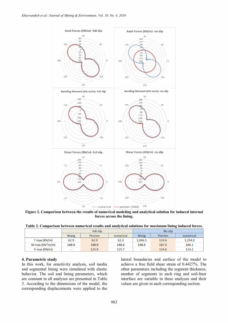
Figure 2. Comparison between the results of numerical modeling and analytical solution for induced internal
forces across the lining.
Table 2. Comparison between numerical results and analytical solutions for maximum lining induced forces.
4. Parametric study In this work, for sensitivity analysis, soil media and segmental lining were simulated with elastic behavior. The soil and lining parameters, which are constant in all analyses are presented in Table 3. According to the dimensions of the model, the corresponding displacements were applied to the
lateral boundaries and surface of the model to achieve a free field shear strain of 0.4427%. The other parameters including the segment thickness, number of segments in each ring and soil-liner interface are variable in these analyses and their values are given in each corresponding section.

Kheyrandish et al./ Journal of Mining & Environment, Vol. 10, No. 4, 2019
984
Table 3. Soil and segmental lining parameters used in the parametric study. Unit Value Parameters
KN/m3 19 Unit weight (ɣ)
Soil
m/s 461 Shear wave velocity in soil (Cs) MPa 1050 Modulus of elasticity (Em, dynamic) --- 0.3 Poisson ratio (νm)
MPa 875 Bulk modulus (Km) MPa 404 Shear modulus (Gm) MPa 25000 Modulus of elasticity (E l)
Segments
m 4.55 Radius (r) --- 0.2 Poisson ratio (νl)
Variable Thickness (t) Variable number of segments in each ring (n) variable soil-liner interface condition
4.1. Effect of segmental joint stiffness considering soil-liner interface behavior The numerical model was developed for different axial, radial and rotational stiffness of segmental joints and maximum and minimum induced forces were determined in the structure. For each case, the frictional behavior of the contact surface between the structure and the soil simulated by applying different coefficients of friction equal to zero (equivalent to full-slip mode), 0.4 (contact surface friction angle = 21.8 degrees), 1 (contact surface friction angle = 45 degrees), and 100 (equivalent to no-slip mode). In the no-slip mode, no slipping is allowed along the tangential direction between the lining and the soil and there is no possibility of separation (normal to contact surface) between them. In other words, the strength of the contact surface against tensile stresses is assumed to be infinite. In other models (other than the no-slip condition), there is a possibility of separation (normal to contact surface) between the lining and the ground. The segment thickness is 35 cm, the number of segments in each ring is 8, the arc length of the segments is equal and the position of the closest joint relative to the crown of the tunnel is 21º.
4.1.1. Rotational stiffness of joints In order to investigate the effect of rotational stiffness of the joints, their axial and radial stiffness were considered to be 1 and 0.2 GN/m (Giga Newton per meter), respectively. Figure 3 shows the variations in the minimum and maximum induced axial forces versus the rotational stiffness of the joints in different coefficients of friction at the soil-liner interface. The minimum axial force graphs representing the maximum compressive force induced in the segmental ring and the maximum axial force graphs represent the maximum induced tensile force (the negative and the positive values
indicate the compressive force and the tensile force, respectively). In order to distinguish the difference between the curves, the no-slip graphs are presented separately in the two bottom graphs in the figure (due to the significant differences of values in the no-slip mode compared to the other modes). It should be noted that the horizontal axis in the graphs of this figure and other figures related to the effect of rotational stiffness of joint indicate a non-dimensional rotational stiffness factor called the rotational stiffness ratio (Ƞ). This factor indicates the relative rotational joint stiffness over the bending stiffness of segments (Ƞ = (EI)joint/(EI)lining). As shown in Figure 3, in general, by increasing the rotational stiffness of the joints, the maximum induced axial force tends to become a tensile-type force and then will increase. It means that in cases where the maximum axial force is of a compressive type (with a negative value), increasing the rotational joint stiffness reduces that, and in cases where the axial force is of a tensile type (with a positive value), increasing the rotational joint stiffness increases this force. These variations are sensible up to rotational joint stiffness almost equal to the bending stiffness of segments (Ƞ = 1). After that, the stiffness variation will not have a significant effect on the maximum and minimum of axial forces. On the other hand, according to the two graphs on the right side of the figure, increasing the friction at the soil-liner interface also increases the maximum axial compressive force. In low friction coefficients, the maximum and minimum axial forces have a negative value. This means that all induced axial forces are of a compressive type and as friction increases, part of these forces will be converted into tensile forces. In the no-slip mode (two graphs on the bottom of the figure), the maximum axial compressive and tensile forces are significantly higher than their corresponding

Kheyrandish et al./ Journal of Mining & Environment, Vol. 10, No. 4, 2019
985
values in other frictional coefficients. It is noteworthy that in different coefficients of friction, except for the no-slip mode, the trend of changing of maximum axial forces in relation to the variation in rotational joint stiffness is almost the same. This means that in each graph, the curves corresponding to different frictional coefficients are almost parallel. Thus it can be said that the effect of rotational joint stiffness and frictional coefficient at the soil-liner interface on the maximum induced axial forces is almost independent from each other. As mentioned earlier, this is not the case for the no-slip condition. Figure 4 shows the maximum induced bending moments developed in segmental ring versus rotational joint stiffness ratio in different coefficients of friction at the soil-liner interface. The positive and negative signs indicate the bending moment direction. In order to distinguish the difference between the curves, the no-slip graphs are presented separately in the two bottom graphs in the figure. The results obtained show that increasing the rotational stiffness increases the maximum induced bending moments (both positive and negative). This is not the case for positive bending moments in the no-slip mode. As shown in Figure 4, this effect decreases in a high rotational stiffness. On the other hand, the effect of frictional behavior at the soil-liner interface on
maximum bending moments is less that its effect on the maximum axial forces (see Figure 3). Also in the no-slip mode, the effect of the rotational stiffness on the induced bending moments is less than its effect in the other interface conditions. In order to normalize the shear forces and bending moments in segmental lining, a numerical model with continuous concrete lining, considering the same geometry, boundary condition and properties of concrete was built. In order to normalize the bending moments, in each case, the determined maximum bending moment in the segmental ring was divided into the corresponding determined maximum bending moment in the continuous lining (it is also about shear forces). As shown in Figure 5, except for the no-slip mode, by increasing the rotational stiffness of joints, the normalized ratio of maximum bending moments increases. In a high rotational stiffness, this ratio is approximately equal to one. This means that in a high rotational joint stiffness, the maximum bending moments in segmental lining and continuous lining are almost equal. In the no-slip mode, the effect of rotational stiffness on the maximum bending moments is less. On the other hand, in this case, the normalized ratio of maximum bending moments is greater than one. This means that in the no-slip mode, the segmental lining does not reduce the maximum induced moments and in the case of positive bending moments increases them.
Figure 3. Axial forces vs. rotational stiffness ratio in different coefficients of friction at the soil-liner interface.

Kheyrandish et al./ Journal of Mining & Environment, Vol. 10, No. 4, 2019
986
Figure 4. Bending moments vs. rotational stiffness ratio in different coefficients of friction at the soil-liner
interface.
Figure 5. Normalized ratio of maximum bending moments vs. rotational stiffness ratio in different coefficients of
friction at the soil-liner interface.
Figure 6 shows the maximum induced shear forces versus rotational joint stiffness ratio in different soil-liner frictional coefficients. The positive and negative signs indicate the shear force direction. In the graphs, the minimum values for shear forces with negative signs are in fact maximum shear forces in the opposite direction of the positive values in the local coordinate system of the beam element. Except for the no-slip mode, in other cases, the rotational stiffness has no significant effect on the maximum shear forces in segments; although with increasing stiffness the maximum shear forces decrease slightly at first and then with a further increase in the rotational
stiffness, the maximum shear forces increase. As in the case for bending moments, except for the no-slip mode, the change in the frictional coefficient at the soil-liner interface does not produce significant changes in maximum induced shear forces. As shown in Figure 7, although the rotational stiffness variation has no appreciable effect on the maximum normalized shear forces, this ratio is still less than 1, except for the no-slip mode. This means that the maximum induced shear forces are reduced in comparison with continuous lining, while in the no-slip mode, it is vice versa.

Kheyrandish et al./ Journal of Mining & Environment, Vol. 10, No. 4, 2019
987
Figure 6. Shear forces vs. rotational stiffness ratio in different coefficients of friction at the soil-liner interface.
Figure 7. Normalized ratio of maximum shear forces vs. rotational stiffness ratio in different coefficients of
friction at the soil-liner interface. 4.1.2. Axial stiffness of joints For this purpose, a radial stiffness of 0.2 GN/m and a rotational stiffness ratio (Ƞ) of 0.5 were considered and kept constant. As in the previous section, Figures 8, 9, and 10 show the maximum induced forces in segmental ring versus axial joint stiffness in different soil-liner frictional coefficients. According to Figure 8, an increase in the axial stiffness of joints increases the maximum axial compressive type forces (with a negative sign). Except for the no-slip mode, in different coefficients of friction at the interface, the trend of changing of maximum axial forces (both in compression and tension) in relation to the variation in axial joint stiffness is almost same.
Thus the effect of axial joint stiffness and frictional coefficient at the soil-liner interface on maximum induced axial forces is almost independent of each other. Here too, in the no-slip mode, the trend of changing of maximum axial forces is different from that of the other modes. On the other hand, in the case of maximum axial forces, in low frictional coefficients of the soil-liner interface, these forces are also of compressive type. Thus all the induced forces are of compressive type in low friction angles of the interface. With increase in the friction, the maximum axial force tends to become a tensile-type force. Thus in this case, part of the axial forces is of tensile type and another part is of compressive type.

Kheyrandish et al./ Journal of Mining & Environment, Vol. 10, No. 4, 2019
988
As shown in Figure 9, except for the no-slip mode, in other frictional coefficients, the variation in the axial stiffness does not result in noticeable changes in maximum induced bending moments. Under the no-slip condition, increasing the axial joint stiffness increases the maximum bending moment (either with a positive or a negative sign).
According to Figure 10, the same results are valid about the maximum induced shear forces in segmental ring. It means that the variation in the axial stiffness does not significantly change the maximum shear forces induced in the segmental structure.
Figure 8. Axial forces vs. axial stiffness of joints in different coefficients of friction at the soil-liner interface.
Figure 9. Bending moments vs. axial stiffness of joints in different coefficients of friction at the soil-liner
interface.

Kheyrandish et al./ Journal of Mining & Environment, Vol. 10, No. 4, 2019
989
Figure 10. Shear forces vs. axial stiffness of joints in different coefficients of friction at the soil-liner interface.
According to Figures 11 and 12, except for the no-slip mode, the variation in the axial stiffness does not result in noticeable changes in maximum normalized bending moments and maximum normalized shear forces. In the no-slip mode, with increase in the axial joint stiffness, the normalized
ratio increases and then reaches an almost constant amount greater than one. This means that in the no-slip mode, the segmental lining does not reduce the maximum induced shear forces and moments and in the case of positive shear forces and bending moments increases them.
Figure 11. Normalized ratio of maximum bending moments vs. axial stiffness of joints in different coefficients of
friction at the soil-liner interface.
Figure 12. Normalized ratio of maximum shear forces vs. axial stiffness of joints in different coefficients of
friction at the soil-liner interface.

Kheyrandish et al./ Journal of Mining & Environment, Vol. 10, No. 4, 2019
990
4.1.3. Radial stiffness of joints In this case, the axial stiffness and the rotational stiffness ratio (Ƞ) are constant and are respectively 1 GN/m and 0.5. Different degrees of radial stiffness were considered in each model. Figures 13, 14, and 15 show the maximum induced forces in segmental ring versus radial joint stiffness in different soil-liner frictional coefficients. According to the graphs in Figure 13, the significant difference in curves of the graphs shows that the frictional behavior at the soil-liner interface has a significant effect on the maximum axial forces induced in segments but the variation in radial stiffness of the joints does not cause significant changes in the maximum tensile and compressive axial forces. In low frictional coefficients of soil-liner interface, all axial forces are of compressive type (with a negative value). With increasing friction, the maximum axial force tends to become a tensile-type force (thus in this
case, part of the axial forces is of tensile type and another part is of compressive type). As shown in Figure 14, first, increasing the radial joint stiffness slightly increases the maximum bending moments, and then the effect of a further increase is negligible. According to Figure 15, the same result was obtained for induced shear forces in the segmental ring. This means that increasing the radial stiffness slightly increases the maximum shear forces at first, and then the effect of its further increase is not significant. Figures 16 and 17 show maximum normalized bending moments and shear forces versus radial joint stiffness. Similar to Section 4.1.2, except for the no-slip mode, the variation in the radial stiffness does not result in noticeable changes in maximum normalized bending moments and maximum normalized shear forces. In the no-slip mode, with increase in the radial joint stiffness, the normalized ratio increases to some extent and reaches an almost constant amount.
Figure 13. Axial forces vs. radial stiffness of joints in different coefficients of friction at the soil-liner interface.

Kheyrandish et al./ Journal of Mining & Environment, Vol. 10, No. 4, 2019
991
Figure 14. Bending moments versus radial stiffness of joints in different coefficients of friction at the soil-liner
interface.
Figure 15. Shear forces versus radial stiffness of joints in different coefficients of friction at the soil-liner
interface.

Kheyrandish et al./ Journal of Mining & Environment, Vol. 10, No. 4, 2019
992
Figure 16. Normalized ratio of maximum bending moments versus radial stiffness of joints in different
coefficients of friction at the soil-liner interface.
Figure 17. Normalized ratio of maximum shear forces versus radial stiffness of joints in different coefficients of
friction at the soil-liner interface.
4.2. Effect of segmental joint stiffness considering number of segments In order to study this, in the model, the number of segments in each segmental ring was considered to be 6 and 8. The soil-liner interface behavior was simulated in two ways: one considering frictional behavior in tangential direction with friction coefficient of 0.4 and the possibility of separation of segmental parts from the surrounding soil and the other in the no-slip mode. In the no-slip condition, no slipping was allowed along the tangential direction and there was no possibility of separation of segmental parts from the surrounding soil (i.e. the tensile strength of the contact surface was assumed to be infinite). The numerical models were prepared for different axial, radial and rotational stiffnesses of segmental joints, and maximum and minimum induced forces were determined in the structure. In all cases, the thickness of segments is 35 cm, the arc length of segments is equal and the angular position of the closest segmental joint related to the tunnel crown is 21º. Also in the study of the effect of each type of joint stiffness, the other two were kept constant, similar to the previous
sections. Figure 18 shows the variation in the minimum and maximum induced axial forces versus the rotational, axial and radial stiffness of joints in different numbers of segments and considering the frictional behavior at the soil-liner interface. Maximum axial forces with positive values are related to the maximum tensile-type axial forces and minimum axial forces with negative values are related to the maximum compressive type axial forces. Figure 19 shows the results for the no-slip mode. Frictional coefficient at the soil-liner interface= 0.4 and separation at the interface is allowed. As it can be seen in these two figures, with a change the number of segments in each segmental ring, the trend of changing of maximum axial forces in relation to the variation in rotational, axial and radial joint stiffness (in the case of a certain type of stiffness) is almost same. This means that in each graph, the two curves corresponding to different numbers of segments have similar trends. This suggests that the effect of joint stiffness and number of segments on maximum induced axial forces is almost independent from each other but in a certain value

Kheyrandish et al./ Journal of Mining & Environment, Vol. 10, No. 4, 2019
993
of joint stiffness, a change in the number of segments affects the values of these forces in such a way that increasing the number of segments decreases the maximum tensile and compressive forces. On the other hand, the greatest effect of the number of segmental parts on the axial forces is in the no-slip mode and in the case of induced tensile forces so that the reduction in the number of parts from 8 to 6 has increased the maximum induced tensile force for approximately two times. Figure 20 shows the variations in the minimum and maximum induced bending moments versus the rotational, axial and radial stiffness of joints in different numbers of segments (6 and 8), considering the frictional behavior at the soil-liner interface. Due to the similarity of the results obtained, the graphs for the no-slip mode are not presented. Figure 20 indicates the number of segments affecting the trend of changing of maximum bending moments in relation to the variation in joint stiffness. With increase in the number of segments in each ring, the effect of variation in rotational, axial and radial stiffness on bending moments increases. Thus if more segmental parts
are used, the design of the joints should be considered more carefully. Also in a certain joint stiffness, the number of parts affects the values for these moments. Figure 21 shows maximum normalized bending moments versus rotational stiffness of joints in different numbers of segments (6 and 8). In this Figure, the graphs are plotted only by considering the friction coefficient of 0.4 for the soil-liner interface. As it can be seen, with increase in the rotational stiffness of joints, for both numbers of segments, the normalized ratio of maximum bending moments increase and the two curves (related to different numbers of segments) get closer together. In a high rotational stiffness, this ratio is approximately equal to one for both numbers of segments. This means that in a high rotational joint stiffness, the maximum bending moments in segmental lining and continuous lining are almost equal. In the case of axial and radial stiffness of joints, the normalized bending moments are not presented because of their similar trends corresponding to different numbers of segments.
Figure 18. Axial forces versus rotational, axial and radial stiffness of joints in different numbers of segments.

Kheyrandish et al./ Journal of Mining & Environment, Vol. 10, No. 4, 2019
994
Figure 19. Axial forces versus rotational, axial and radial stiffness of joints in different numbers of segments in
the no-slip mode.
Figure 20. Bending moments versus rotational, axial and radial stiffness of joints in different numbers of segments. Frictional coefficient at the soil-liner interface = 0.4 and separation at the interface is allowed.

Kheyrandish et al./ Journal of Mining & Environment, Vol. 10, No. 4, 2019
995
Figure 21. Normalized ratio of maximum bending moments versus rotational stiffness of joints in
different numbers of segments. Frictional coefficient at the soil-liner interface = 0.4 and separation at the interface is allowed.
Figure 22 shows the variations in the minimum and maximum induced shear forces versus the rotational, axial and radial stiffness of joints in different numbers of segments and considering the frictional behavior at the soil-liner interface. In different numbers of segments, the trends of changing of maximum shear forces in relation to the variation in joint stiffness are approximately
the same. This means that in each graph two curves corresponding to different numbers of segments have similar trends. This suggests that the effects of joint stiffness and number of segments on the maximum induced shear forces are almost independent from each other but in a certain value of joint stiffness, a change in the number of parts affects the values of these forces.
Figure 22. Shear forces versus rotational, axial and radial stiffness of joints in different numbers of segments.
Frictional coefficient at the soil-liner interface = 0.4 and separation at the interface is allowed.

Kheyrandish et al./ Journal of Mining & Environment, Vol. 10, No. 4, 2019
996
4.3. Effect of segmental joint stiffness considering segment thickness In order to evaluate the effect of segment thickness on the relation between joint stiffness and induced forces; modeling was done for segment thicknesses of 35 and 55 cm. For each case, the condition at the soil-liner interface was simulated considering the frictional coefficient of 0.4 and possibility of separation of segmental ring from the surrounding soil. Numerical modeling was carried out for different axial, radial and rotational stiffnesses of segmental joints, and maximum and minimum induced forces were determined in the structure. Figures 23, 24 and 25 show the variations in minimum and maximum induced forces versus the rotational, axial and radial stiffness of joints in different segment thicknesses. In these models, the number of segments in each ring is 8, the arc lengths of segments are equal, and the angular position of the closest segmental joint related to the tunnel crown is 21º. Changing the segment thickness affects the trend of changing of maximum axial forces and bending moments in relation to the variation in the joint stiffness. By increasing the thickness, the effect of joint stiffness variation on induced axial forces and bending moments increases, especially in the
case of variation in rotational stiffness of joints. Therefore, design and choosing of joints should be considered more carefully when segments with a high thickness are used. The effect of thickness variation on the relation between the stiffness of joints and the maximum shear forces is approximately negligible, and in each graph, the curves corresponding to different thicknesses have the same trend. By increasing the thickness of the segments, in a specified joint stiffness, the maximum compressive and tensile axial forces induced in the structure increase. This is also correct, in accordance with Figures 24 and 25, for maximum bending moments and shear forces. The same as the previous sections, for different thicknesses, the internal forces in segmental lining are normalized to the continuous lining forces. It is worth noting that in all cases, the normalized curves related to higher thicknesses are below the curves corresponding to lower thicknesses. This means that by increasing the segment thickness, the relative reduction in the internal forces relative to the continuous lining (with the same thickness) decreases. As an example, to demonstrate the correctness of this, the maximum normalized bending moments versus the rotational stiffness of joints in different thicknesses of segmental ring are shown in Figure 26.
Figure 23. Axial forces versus rotational, axial and radial stiffness of joints in different segment thicknesses.
Frictional coefficient at the soil-liner interface = 0.4, allowing separation at the interface.

Kheyrandish et al./ Journal of Mining & Environment, Vol. 10, No. 4, 2019
997
Figure 24. Bending moments versus rotational, axial and radial stiffness of joints in different segment thicknesses. Frictional coefficient at the soil-liner interface = 0.4, allowing separation at the interface.
Figure 25. Shear forces versus rotational, axial and radial stiffness of joints in different segment thicknesses.
Frictional coefficient at the soil-liner interface = 0.4, allowing separation at the interface.

Kheyrandish et al./ Journal of Mining & Environment, Vol. 10, No. 4, 2019
998
Figure 26. Normalized ratio of maximum bending moments versus rotational stiffness of joints in different
segment thicknesses. Frictional coefficient at the soil-liner interface = 0.4, allowing separation at the interface. 5. Conclusions The effect of segmental joints on the internal forces induced in the lining due to seismic loading was investigated numerically. In the previous research works, the effect of joints has been studied only by assuming a specified condition at the soil-liner interface. In this work, the effects of segmental joints and the soil-liner interface on the induced internal forces were investigated simultaneously and in relation to each other. In addition, this paper highlighted the effect intensity of these joints in different thicknesses of segments and different numbers of segments in each ring. For this purpose, the 2D numerical analyses were performed using the ABAQUS software. The main conclusions of this work can be summarized as follow:
By increasing the rotational stiffness of joints, the maximum compressive axial forces reduce and tend to become tensile, and then these tensile forces increase. Also increasing the rotational stiffness increases the maximum induced bending moment. These variations are sensible and significant up to the rotational joint stiffness, almost equal to the bending stiffness of segments (Ƞ = 1). In the case of axial stiffness of the joints, the results obtained show that by increasing the stiffness, the maximum tensile axial forces reduce and tend to become compressive and then rise in the compressive type. However, its effect on the maximum bending moments and shear forces is less important. The radial stiffness of the segmental joints generally has a less effect than the effect of the rotational and axial stiffness. It should be noted that by using the segmental joint connections with a higher axial stiffness and less rotational stiffness, generally, the tensile axial forces (that most of the time are more important in design) will decrease. In addition, by using the joints with less rotational stiffness, the maximum
bending moments and maximum tensile axial forces reduce.
About the effect of the soil-liner interface properties on the relation between joint stiffness and induced forces, in different coefficients of friction at the interface, except for the no-slip mode, the trend of changing of maximum internal forces and bending moments in relation to the variation in joint stiffness (in the case of a certain type of stiffness) is approximately the same. In fact, the effect of joint stiffness and frictional coefficient at the soil-liner interface on maximum induced forces is almost independent from each other, so it can be said that in the design of the segmental joints, the properties of the soil-liner interface do not have much effect.
Variation in the number of segments in each ring, except for the case of bending moments, does not make a significant change in the effect of stiffness on the maximum induced forces. Changing the number of segments affects the trend of changing of maximum bending moments in relation to the variation in the joint stiffness. By increasing the number of segments in each ring, the effect of joint stiffness on bending moments increases. Thus if more segmental parts are used, design of the joints should be considered more carefully.
By increasing the thickness of segments, the effects of variation in rotational, axial and radial stiffness on the induced axial forces and bending moments increase, especially in the case of variation in the rotational stiffness of joints. Therefore, the design of joints should be considered more carefully when segments with a high thickness are used. Also by increasing the thickness of segments in a specified joint stiffness, the forces induced in the structure increase.

Kheyrandish et al./ Journal of Mining & Environment, Vol. 10, No. 4, 2019
999
References [1]. Owen, G.N. and Scholl, R.E. (1981). Earthquake engineering of large underground structures, report No. FHWA/RD-80/195, Federal Highway Administration and National Science Foundation, Washington D.C.
[2]. AFPS/AFTES. (2001). Guidelines on earthquake design and protection of underground structures, Version 1, Working group of the French association for seismic engineering (AFPS) and French Tunneling Association (AFTES).
[3]. Gil, L.M., Hernandez, E. and De la Fuente, P. (2001). Simplified transverse seismic analysis of buried structures. Soil Dynamics and Earthquake Engineering. 21 (8): 735-740.
[4]. ISO 23469 (2005). Bases for design of structures-seismic actions for designing geotechnical works, 1st Ed., ISO International Standard.
[5]. Manoogian, M.E. and Lee, V.W. (1996). Diffraction of SH-waves by subsurface inclusions of arbitrary shape. Journal of Engineering Mechanics. 122: 123-129.
[6]. Stamos, A.A. and Beskos, D.E. (1996). 3D seismic response analysis of long lined tunnels in half-space. Soil Dynamics and Earthquake Engineering. 15 (2): 111-118.
[7]. Sederat, H., Kozak, A., Hashash, Y.M.A., Shamsabadi, A. and Krimotat, A. (2009). Contact interface in seismic analysis of circular tunnels. Tunnelling and Underground Space Technology. 24 (4): 482-490.
[8]. Penzien, J. and Wu, C.L. (1998). Stresses in linings of bored tunnels. Earthquake Engineering Structural Dynamics. 27 (3): 283-300.
[9]. Wang, J.N. (1993). Seismic design of tunnels: a state-of-the-art approach, Brinckerhoff Quade and Douglas Inc, New York. 147 P.
[10]. Park, K.H., Tantayopin, K., Tontavanich, B. and Owatsiriwong, A. (2009). Analytical solution for seismic-induced ovaling of circular tunnel lining under no-slip interface conditions: a revisit. Tunnelling and Underground Space Technology. 24 (2): 231-235.
[11]. Kouretzis, G.P., Andrianopoulos, K.I., Sloan, S.W. and Carter, J.P. (2014). Analysis of circular tunnels due to seismic P-wave propagation, with emphasis on unreinforced concrete liners, Computers and Geotechnics. 55: 187-194.
[12]. Hashash, Y.M.A., Hook, J.J., Schmidt, B. and Yao, J.I.C. (2001). Seismic design and analysis of underground structures. Tunnelling and Underground Space Technology. 16: 247-293.
[13]. Hashash, Y.M.A., Park, D. and Yao, J.I.C. (2006). Ovaling deformations of circular tunnels under seismic loading, an update on seismic design and
analysis of underground structures, Tunnelling and Underground Space Technology. 20: 435-441.
[14]. Kouretzis, G., Sloan, S.W. and Carter, J.P. (2013), Effect of interface friction on tunnel liner internal forces due to seismic S- and P-wave propagation. Soil Dynamics and Earthquake Engineering. 46: 41-51.
[15]. Dean, A., Young, D.J. and Kramer, G.J.E. (2006). The use and performance of precast concrete tunnel linings in seismic areas, IAEG 2006, Geological Society of London 2006. Paper 679.
[16]. Kaneshiro, J. and Sinha, M. (2008). Simplified seismic design approach using pushover considerations and ring compression theory for a concrete segmented liner, in Proceedings of the world tunnel congress - underground facilities for better environment and safety, India. pp. 462-472.
[17]. Nikkhah, M., Mousavi, S.S., Zare, S. and Khademhosseini, O. (2017). Evaluation of structural analysis of tunnel segmental lining using beam-spring method and force-method (case study: Chamshir water conveyance tunnel). Journal of Mining and Environment. 8: 111-130
[18]. Kramer, G.J., Sederat, H., Kozak, A., Liu, A. and Chai, J. (2007). Seismic response of precast tunnel lining, Proceedings of the rapid excavation and tunneling conference. pp. 1225-1242.
[19]. He, C. and Koizumi, A. (2000), Dynamic behavior in transverse direction of shield tunnel with considering effect of segment joints, 12WCEE 2000. Paper 362.
[20]. Chow, W.L., Tang, S.K. and Tong, S.Y. (2009). Design of segmental tunnel lining in an earthquake zone, AMBERG & TTI Engineering Pte Ltd., the strategy 2 international business park, Singapore 609930.
[21]. Naggar, H.E. and Hinchberger, S.D. (2012), Approximate evaluation of stresses in degraded tunnel linings. Soil Dynamics and Earthquake Engineering. 43: 45-57.
[22]. Do, N.A., Dias, D., Oreste, P.P. and Djeran-Maigre, I. (2015), 2D numerical investigation of segmental tunnel lining under seismic loading. Soil Dynamics and Earthquake Engineering. 72: 66-76.
[23]. Abaqus/Standard–User’s manual, version 6.14. Dassault Systemes Simulia Corp.
[24]. Zurlo, M.A. (2012). Seismic response of circular tunnels: numerical validation of closed form solutions, In: Proceedings of the 1st civil and environmental engineering student conference, Imperial College London, 25-26 June.
[25]. Kontoe, S., Zdravkovic, L., Potts, D.M. and Menkiti, C.O. (2008), Case study on seismic tunnel response. Canadian Geotech J. 45: 1743-1764.

1398 م، سالچهاردوره دهم، شماره زیست، پژوهشی معدن و محیط - و همکاران/ نشریه علمی خیراندیش
تونل بر بارهاي القایی در آن تحت بارگذاري ناشی از بررسی عددي تأثیر رفتار اتصالات بین سگمنتی پوشش زلزله
2و حسین جهانخواه *1احمدي، مرتضی 1ایمان خیراندیش
ایران مدرس، تربیت دانشگاه معدن، مهندسی بخش - 1شناسی و مهندسی زلزله، ایرانالمللی زلزلهپژوهشگاه بین - 2
23/7/2019، پذیرش 29/5/2019ارسال
[email protected]* نویسنده مسئول مکاتبات:
چکیده:
به وجود اتصالات عموماً هاي بتنی پیوسته،هاي سگمنتی در نگهداري فضاهاي زیرزمینی نسبت به پوششعملکرد بهتر پوشش اي ناشی از زلزله،لرزه در بارگذاريبـر میـزان و نـوع مـؤثر در کنار سایر پارامترهـاي ها آنرفتار يمشخصهپارامترهاي تأثیراي مرتبط است. براي شناخت بهتر رفتار اتصالات باید میزان بین قطعه
سازي شده و نوع و شـدت اثرگـذاري ایـن شبیهمشخصه هايرفتار اتصالات بین سگمنتی با سختی پژوهش،هاي القایی در سازه مورد توجه قرار گیرد. در این بار ر هـر حلقـه و د به طور همزمان با سایر پارامترهاي تاثیرگذار از قبیل رفتار سطح تماس پوشش سگمنتی و زمـین، تعـداد قطعـات پوشـش سـگمنتی ها مشخصه
سـازي بـا اسـتفاده از روش مدل. شدبررسی ها دوبعدي تهیه و نتایج تحلیل این مدلعددي هاي مدل. بدین منظور ه استضخامت پوشش مورد بررسی قرار گرفتهـاي محـوري، فتن سه سختی در جهتبا در نظر گرهاي فنر انجام شد. اتصالات بین سگمنتی با استفاده از المان ABAQUSافزار عددي اجزاء محدود و در نرم
نماینـد هایی به مرز مدل که ایجاد کرنش برشی در محـیط مـی استاتیک و با اعمال جابجاییاي به صورت شبهسازي شده و بارگذاري لرزهشبیه شعاعی و پیچشیو لنگرهاي خمشی بیشتر از بوده اتصالات محوريسختی در میزان و نوع بارهاي محوري القایی ناشی از سختی خمشی و تأثیرنتایج بیشترین صورت گرفت. طبق
بـا افـزایش تعـداد قطعـات داشـته و کمتري بر نیروهـاي القـایی تأثیرختی شعاعی اتصالات سگمنتی به طور کلی میزان س. شدند متأثرسختی خمشی اتصالات ضخامت پوشش سگمنتی، میزان تأثیر سختی اتصالات بین سگمنتی بر بارهاي القایی افزایش یافته و در ایـن شـرایط طراحـی طور نیهم سگمنتی در هر حلقه و
اي و زمین بـر باره ـ اتصالات باید با دقت بیشتري مورد توجه قرار گیرد. با توجه به نتایج، تأثیر رفتار اتصالات بین سگمنتی و رفتار سطح تماس پوشش سگمنتیطور در یک شرایط ثابت و رفتار معین اتصالات، با تغییر هر یک از دیگر پارامترها از جمله رفتار سطح تماس پوشش و زمین، . همینباشند یمالقایی مستقل از هم
نند.کاي تغییر پیدا میبه طور قابل توجه بعضاًها، مقدار مطلق حداکثر بارهاي القایی تعداد قطعات سگمنتی و ضخامت آن
اي.روش اجزاء محدود، اتصالات پوشش سگمنتی، اصطکاك سطح تماس، سیستم نگهداري تونل، طراحی لرزه کلمات کلیدي: