A Novel Technique to Improve Gain In Transparent UWB Antennas · of AgHT-8; the primary conducting...
5
Title A novel technique to improve gain in transparent UWB antennas Author(s) Peter, T; Yuk, TI; Nilavalan, R; Cheung, SW Citation The 7th Loughborough Antennas and Propagation Conference (LAPC), Loughborough, United Kingdom, 14-15 November 2011. In Loughborough Antennas and Propagation Conference Proceedings, p. article no. 6114156 Issued Date 2011 URL http://hdl.handle.net/10722/158774 Rights Loughborough Antennas and Propagation Conference Proceedings. Copyright © I E E E.
Transcript of A Novel Technique to Improve Gain In Transparent UWB Antennas · of AgHT-8; the primary conducting...

Title A novel technique to improve gain in transparent UWB antennas
Author(s) Peter, T; Yuk, TI; Nilavalan, R; Cheung, SW
Citation
The 7th Loughborough Antennas and Propagation Conference(LAPC), Loughborough, United Kingdom, 14-15 November 2011.In Loughborough Antennas and Propagation ConferenceProceedings, p. article no. 6114156
Issued Date 2011
URL http://hdl.handle.net/10722/158774
Rights Loughborough Antennas and Propagation ConferenceProceedings. Copyright © I E E E.
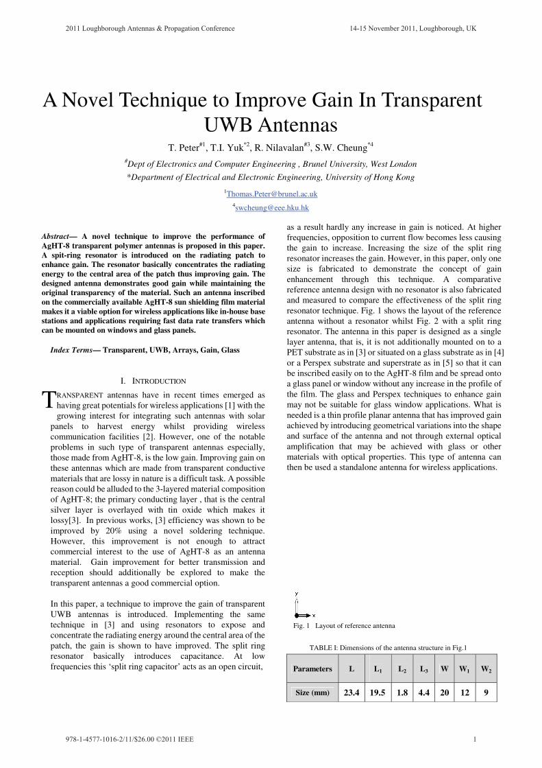
Abstract— A novel technique to improve the performance of AgHT-8 transparent polymer antennas is proposed in this paper. A spit-ring resonator is introduced on the radiating patch to enhance gain. The resonator basically concentrates the radiating energy to the central area of the patch thus improving gain. The designed antenna demonstrates good gain while maintaining the original transparency of the material. Such an antenna inscribed on the commercially available AgHT-8 sun shielding film material makes it a viable option for wireless applications like in-house base stations and applications requiring fast data rate transfers which can be mounted on windows and glass panels.
Index Terms— Transparent, UWB, Arrays, Gain, Glass
I. INTRODUCTION
RANSPARENT antennas have in recent times emerged as having great potentials for wireless applications [1] with the growing interest for integrating such antennas with solar
panels to harvest energy whilst providing wireless communication facilities [2]. However, one of the notable problems in such type of transparent antennas especially, those made from AgHT-8, is the low gain. Improving gain on these antennas which are made from transparent conductive materials that are lossy in nature is a difficult task. A possible reason could be alluded to the 3-layered material composition of AgHT-8; the primary conducting layer , that is the central silver layer is overlayed with tin oxide which makes it lossy[3]. In previous works, [3] efficiency was shown to be improved by 20% using a novel soldering technique. However, this improvement is not enough to attract commercial interest to the use of AgHT-8 as an antenna material. Gain improvement for better transmission and reception should additionally be explored to make the transparent antennas a good commercial option.
In this paper, a technique to improve the gain of transparent
UWB antennas is introduced. Implementing the same technique in [3] and using resonators to expose and concentrate the radiating energy around the central area of the patch, the gain is shown to have improved. The split ring resonator basically introduces capacitance. At low frequencies this ‘split ring capacitor’ acts as an open circuit,
as a result hardly any increase in gain is noticed. At higher frequencies, opposition to current flow becomes less causing the gain to increase. Increasing the size of the split ring resonator increases the gain. However, in this paper, only one size is fabricated to demonstrate the concept of gain enhancement through this technique. A comparative reference antenna design with no resonator is also fabricated and measured to compare the effectiveness of the split ring resonator technique. Fig. 1 shows the layout of the reference antenna without a resonator whilst Fig. 2 with a split ring resonator. The antenna in this paper is designed as a single layer antenna, that is, it is not additionally mounted on to a PET substrate as in [3] or situated on a glass substrate as in [4] or a Perspex substrate and superstrate as in [5] so that it can be inscribed easily on to the AgHT-8 film and be spread onto a glass panel or window without any increase in the profile of the film. The glass and Perspex techniques to enhance gain may not be suitable for glass window applications. What is needed is a thin profile planar antenna that has improved gain achieved by introducing geometrical variations into the shape and surface of the antenna and not through external optical amplification that may be achieved with glass or other materials with optical properties. This type of antenna can then be used a standalone antenna for wireless applications.
A Novel Technique to Improve Gain In Transparent UWB Antennas
T. Peter#1, T.I. Yuk*2, R. Nilavalan#3, S.W. Cheung*4 #Dept of Electronics and Computer Engineering , Brunel University, West London
*Department of Electrical and Electronic Engineering, University of Hong Kong
[email protected] [email protected]
T
Fig. 1 Layout of reference antenna
TABLE I: Dimensions of the antenna structure in Fig.1
Parameters L
L1
L2 L3 W W1 W2
Size (mm) 23.4 19.5 1.8 4.4 20 12 9
2011 Loughborough Antennas & Propagation Conference 14-15 November 2011, Loughborough, UK
1978-1-4577-1016-2/11/$26.00 ©2011 IEEE

II. AGHT-8
The film is a polyethylene terephthalate (PET) with a three-layered transparent conductive coating of silver sandwiched between two layers of tin oxide. The film has a surface resistance of 8 �-Sq which is equivalent to a conductivity (σ) of 1.25 x 10⁵ S/m [1], and a total thickness of 0.175 mm. However, the coating thickness is around 0.052 mm or 52 μm. The DC conductivity of the film was measured as 50000 S/m using the four-probe technique. The PET has a dielectric of 3.24. Using the formula in Equation 1 [6], the skin depth of the AgHT-8 was estimated at 45 μm at 1GHz, 17 μm at 6.85 GHz and 14 μm at 10.6 GHz. The thickness of the film is more than one skin depth from 1GHz to 10.6 GHz and even at higher frequencies as can be seen in the descending skin depth values for increasing frequencies. As such even though the coating is around 52 μm in thickness, ohmic losses due to skin depth is negligible.
... (Eqn 1)
where
� = the skin depth in metres �r = the relative permeability of the medium � = the resistivity of the medium in �·m, also equal to the reciprocal of its conductivity: � = 1 / � f = the frequency of the current in Hz
.
TABLE II: Dimensions of the antenna structure in Fig.2
III. ANTENNA DESIGN
The two UWB antennas were designed with a coplanar waveguide (CPW) feed and fabricated using the AgHT-8 film. The radiator, CPW feed and grounds are designed on the conductive coating portion. The antenna is designed as a rectangular patch with bevels at the bottom portion for impedance matching. Flaps are introduced on opposite edges for the rectangular patch for impedance matching as well as bandwidth enhancement. The 50 � CPW line is 1.8mm in width with a strip gap of 0.1mm on both sides of the central feed line. The total dimensions of the antenna including the substrate are 20 x 20 x 0.175mm. The antenna is compact and optically transparent. The antenna with the above dimensions and parameter is designed as the reference antenna while the other antenna is designed with a cavity in the central section of the radiator and incorporated with a split ring resonator. The antenna with the split ring resonator has a split ring resonator within a cavity in the patch. The split ring resonator is joined on both sides to the edges of the cavity as seen in Fig.2. The split ring has an external radius of 1.8 mm and an internal radius of 1.2mm. The dimensions of the ring can be increased for more gain but the above dimensions are adhered to as a proof of concept. The co-axial cables were connected to the feed points using the same soldering techniques as described in [3].
IV. MEASUREMENT AND SIMULATION RESULTS
The antennas were designed and simulated on CST Microwave Studio. The antennas performances were verified by fabricating them and measuring the return loss. The fabricated prototypes are shown in Fig. 3.
Parameters L4
W3 R1 R2
Size (mm) 9.8 5 1.8 1.2 (a) Fig. 2 (a) Layout of antenna incorporating a split ring resonator
2011 Loughborough Antennas & Propagation Conference 14-15 November 2011, Loughborough, UK
2
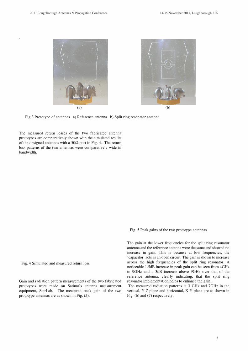
. The measured return losses of the two fabricated antenna prototypes are comparatively shown with the simulated results of the designed antennas with a 50� port in Fig. 4. The return loss patterns of the two antennas were comparatively wide in bandwidth. Gain and radiation pattern measurements of the two fabricated prototypes were made on Satimo’s antenna measurement equipment, StarLab. The measured peak gain of the two prototype antennas are as shown in Fig. (5).
The gain at the lower frequencies for the split ring resonator antenna and the reference antenna were the same and showed no increase in gain. This is because at low frequencies, the ‘capacitor’ acts as an open circuit. The gain is shown to increase across the high frequencies of the split ring resonator. A noticeable 1.5dB increase in peak gain can be seen from 4GHz to 9GHz and a 3dB increase above 9GHz over that of the reference antenna, clearly indicating, that the split ring resonator implementation helps to enhance the gain. The measured radiation patterns at 3 GHz and 7GHz in the vertical, Y-Z plane and horizontal, X-Y plane are as shown in Fig. (6) and (7) respectively.
Fig. 5 Peak gains of the two prototype antennas
(a) (b)
Fig.3 Prototype of antennas a) Reference antenna b) Split ring resonator antenna
Fig. 4 Simulated and measured return loss
2011 Loughborough Antennas & Propagation Conference 14-15 November 2011, Loughborough, UK
3
IV. CONCLUSIONS
A novel technique is proposed to improve the performance of polymer based antennas made of transparent conductive materials by introducing split ring resonators into the radiating patch portion of the antenna in this case a UWB antenna. The results showed that the proposed technique can be used to increase the gain of the antenna and thus improve the performance of the transparent polymer UWB antenna. The increased gain makes the radiation pattern slightly directional, however, a nearly omni-directional radiation pattern is still maintained thus ensuring good reception and transmission in all directions. The wide bandwidth achieved further solidifies the effectiveness of this technique for gain enhancement in transparent polymer UWB antennas.
The possibility of further increasing the gain was noted in simulation by increasing the dimensions of the split ring resonator. Also possible is the introduction of other similar shapes to increase the gain further but this has been left to future works.
ACKNOWLEDGMENT
The authors wish to acknowledge Solutia Inc., St. Louis, Missouri, USA for their support in providing the AgHT-8 films used in this research.
REFERENCES [1] T. Peter and R. Nilavalan, "Study on the performance deterioration of flexible UWB antennas," Antennas and Propagation Conference Loughborough (LAPC’09), pp. 669-672, 2009. [2] Peter, T.; Sun, Y.Y.; Yuk, T.I.; AbuTarboush, H.F.; Nilavalan, R.; Cheung, S.W.; , "Miniature transparent UWB antenna with tunable notch for green wireless applications," Antenna Technology (iWAT), 2011 International Workshop on , vol., no., pp.259-262, 7-9 March 2011 [3] T. Peter, R. Nilavalan, H. F. AbuTarboush, and S. W. Cheung, "A Novel Technique and Soldering Method to Improve Performance of Transparent Polymer Antennas," IEEE Antennas and Wireless Propagation Letters, vol.9, no., pp.918-921, 2010. [4] Mias, C.; Tsakonas, C.; Prountzos, N.; Koutsogeorgis, D.C.; Liew, S.C.; Oswald, C.; Ranson, R.; Cranton, W.M.; Thomas, C.B.; , "Optically transparent microstrip antennas," Antennas for Automotives (Ref. No. 2000/002), IEE Colloquium on , vol., no., pp.8/1-8/6, 2000. �������Katsounaros, A.; Hao, Y.; Collings, N.; Crossland, W.A.; , "Optically transparent antenna for Ultra Wide-Band applications," Antennas and Propagation, 2009. EuCAP 2009. 3rd European Conference on , vol.,
no., pp.1918-1921, 23-27 March 2009. [6] J.D. Jackson, “Classical Electrodynamics”, John Wiley & Sons 1999.
Fig. 6 Measured radiation patterns of the two antennas in the Y-Z planes at 3 GHz, 7 GHz.
Fig. 7 Measured radiation patterns of the two antennas in the X-Y planes at 3 GHz, 7 GHz.
2011 Loughborough Antennas & Propagation Conference 14-15 November 2011, Loughborough, UK
4