A Note on the Effects of Broadcast Antenna Gain, Beam ... · A Note on the Effects of Broadcast...
5
1 A Note on the Effects of Broadcast Antenna Gain, Beam Width and Height Above Average Terrain John L. Schadler - Director of Antenna Development Dielectric L.L.C. Raymond, ME 30 September 2014 Abstract With channel re-pack looming in the broadcasters’ future, and also a possibility of a new modulation scheme, it seems appropriate to re-fresh a topic so important to antenna system design. This paper will examine the effect that antenna gain, beam width and height above average terrain has on the coverage and signal strength of the next generation broadcast system. Introduction U.S. broadcasters planning for the re-pack must make choices about a new antenna system from a variety of designs available. Coinciding with the re-pack is an anticipation of a next generation broadcast system with higher data rates and more channel capacity all leading towards more power equating to higher quality of service. The next generation system will most likely use physical layer pipes (PLP’s) allowing for the tailoring of service area robustness. This technology will require the antenna to provide areas of high signal saturation in order to support the PLP’s carrying data rate intensive services. [1] Elevation Pattern Gain and Efficiency Gain requirements for the new ATSC3.0 depend on transmitter power, and necessary field strength as determined by the data rate to support the services in a given area. By the very basic definition, achieving a given effective radiated power (ERP) is a choice between using a low power transmitter and high gain antenna or vice- versa. However, the use of a high gain antenna requires some special considerations since the higher gain results from narrowing the main beam, hence reducing local field strengths and increasing the field strength near and at the horizon. For the purpose of this discussion, gains and directivity are defined on an RMS basis, thus will be a function of the elevation pattern only. The gain of the antenna is equal to the product of the directivity and the antenna efficiency. = (1) The elevation gain is a function of the number of radiating elements, their spacing and the ilumination or relative radiated amplitude and phase. In order to provide continuous coverage for as far as possible, the elevation pattern must be shaped with null fill and beam tilt by varying the illumination. This of course requires additional energy and thus reduces the aperture efficiency. Illuminations can be as simple as a single point where all the amplitudes and phases are the same for each radiator to very complicated where each radiator has a unique characteristic. Figures 1and 2. Figure 1: Illumination is the amplitude and phase of each radiator which defines the characteristics of the elevation pattern.
Transcript of A Note on the Effects of Broadcast Antenna Gain, Beam ... · A Note on the Effects of Broadcast...

1
A Note on the Effects of Broadcast Antenna Gain,
Beam Width and Height Above Average Terrain
John L. Schadler - Director of Antenna Development
Dielectric L.L.C. Raymond, ME 30 September 2014
Abstract
With channel re-pack looming in the broadcasters’ future,
and also a possibility of a new modulation scheme, it
seems appropriate to re-fresh a topic so important to
antenna system design. This paper will examine the effect
that antenna gain, beam width and height above average
terrain has on the coverage and signal strength of the next
generation broadcast system.
Introduction
U.S. broadcasters planning for the re-pack must make
choices about a new antenna system from a variety of
designs available. Coinciding with the re-pack is an
anticipation of a next generation broadcast system with
higher data rates and more channel capacity all leading
towards more power equating to higher quality of service.
The next generation system will most likely use physical
layer pipes (PLP’s) allowing for the tailoring of service
area robustness. This technology will require the antenna
to provide areas of high signal saturation in order to
support the PLP’s carrying data rate intensive services.
[1]
Elevation Pattern Gain and Efficiency
Gain requirements for the new ATSC3.0 depend on
transmitter power, and necessary field strength as
determined by the data rate to support the services in a
given area. By the very basic definition, achieving a given
effective radiated power (ERP) is a choice between using
a low power transmitter and high gain antenna or vice-
versa. However, the use of a high gain antenna requires
some special considerations since the higher gain results
from narrowing the main beam, hence reducing local field
strengths and increasing the field strength near and at the
horizon. For the purpose of this discussion, gains and
directivity are defined on an RMS basis, thus will be a
function of the elevation pattern only. The gain of the
antenna is equal to the product of the directivity and the
antenna efficiency.
� = �� (1)
The elevation gain is a function of the number of radiating
elements, their spacing and the ilumination or relative
radiated amplitude and phase. In order to provide
continuous coverage for as far as possible, the elevation
pattern must be shaped with null fill and beam tilt by
varying the illumination. This of course requires
additional energy and thus reduces the aperture efficiency.
Illuminations can be as simple as a single point where all
the amplitudes and phases are the same for each radiator
to very complicated where each radiator has a unique
characteristic. Figures 1and 2.
Figure 1: Illumination is the amplitude and phase of each
radiator which defines the characteristics of the elevation
pattern.
2
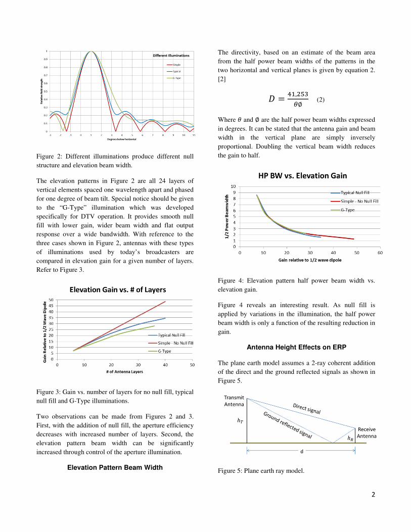
Figure 2: Different illuminations produce different null
structure and elevation beam width.
The elevation patterns in Figure 2 are all 24 layers of
vertical elements spaced one wavelength apart and phased
for one degree of beam tilt. Special notice should be given
to the “G-Type” illumination which was developed
specifically for DTV operation. It provides smooth null
fill with lower gain, wider beam width and flat output
response over a wide bandwidth. With reference to the
three cases shown in Figure 2, antennas with these types
of illuminations used by today’s broadcasters are
compared in elevation gain for a given number of layers.
Refer to Figure 3.
Figure 3: Gain vs. number of layers for no null fill, typical
null fill and G-Type illuminations.
Two observations can be made from Figures 2 and 3.
First, with the addition of null fill, the aperture efficiency
decreases with increased number of layers. Second, the
elevation pattern beam width can be significantly
increased through control of the aperture illumination.
Elevation Pattern Beam Width
The directivity, based on an estimate of the beam area
from the half power beam widths of the patterns in the
two horizontal and vertical planes is given by equation 2.
[2]
� = ��,��∅ (2)
Where and ∅ are the half power beam widths expressed
in degrees. It can be stated that the antenna gain and beam
width in the vertical plane are simply inversely
proportional. Doubling the vertical beam width reduces
the gain to half.
Figure 4: Elevation pattern half power beam width vs.
elevation gain.
Figure 4 reveals an interesting result. As null fill is
applied by variations in the illumination, the half power
beam width is only a function of the resulting reduction in
gain.
Antenna Height Effects on ERP
The plane earth model assumes a 2-ray coherent addition
of the direct and the ground reflected signals as shown in
Figure 5.
Figure 5: Plane earth ray model.
3
The difference in path length between the rays add
differently depending on the distance (d). As the distance
increases the summation passed through a number of
amplitude cycles until the path difference is less than a
half wave. At this breakpoint distance db, given by
equation (3), the fields decay asymptotically [3] [4].
Beyond the breakpoint, the overall path loss (L) becomes
a function of only the antenna heights and the distance
between them and is independent of frequency.
�� = ������ (3)
� = ���������
(4)
Therefore it can be stated that in the region beyond the
breakpoint the effective radiated power (ERP) is
proportional to the square of the transmitting antennas
height above average terrain (HAAT).
��� ∝ !� (5)
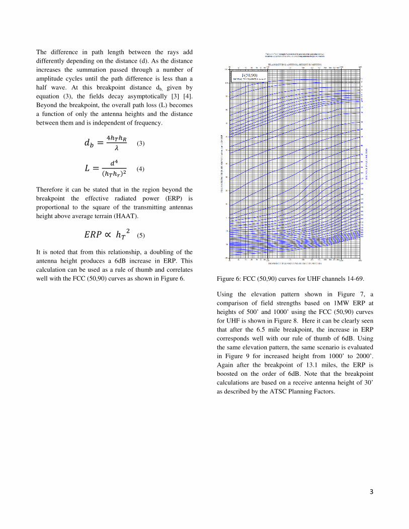
It is noted that from this relationship, a doubling of the
antenna height produces a 6dB increase in ERP. This
calculation can be used as a rule of thumb and correlates
well with the FCC (50,90) curves as shown in Figure 6.
Figure 6: FCC (50,90) curves for UHF channels 14-69.
Using the elevation pattern shown in Figure 7, a
comparison of field strengths based on 1MW ERP at
heights of 500’ and 1000’ using the FCC (50,90) curves
for UHF is shown in Figure 8. Here it can be clearly seen
that after the 6.5 mile breakpoint, the increase in ERP
corresponds well with our rule of thumb of 6dB. Using
the same elevation pattern, the same scenario is evaluated
in Figure 9 for increased height from 1000’ to 2000’.
Again after the breakpoint of 13.1 miles, the ERP is
boosted on the order of 6dB. Note that the breakpoint
calculations are based on a receive antenna height of 30’
as described by the ATSC Planning Factors.

4
Figure 7: Typical elevation pattern of a 24 layer antenna.
Figure 8: Field strength vs. distance from the antenna
using the elevation pattern as shown in Figure 7, based on
1MW ERP and HAAT’s of 500’ and 1000’.
Figure 9: Field strength vs. distance from the antenna
using the elevation pattern as shown in Figure 7, based on
1 MW ERP and HAAT’s of 1000’ and 2000’.
Calculating the Recommended Beam Tilt vs.
Antenna Height
The typical rule of thumb in determining the beam tilt to
provide the most even coverage within the radio horizon
is depicted in Figure 10. The peak of the main beam in the
elevation plane is pointed downward until the relative
field strength at the radio horizon reaches 95%.
Figure 10: Beam tilt location for best overall coverage.
The radio horizon angle can be calculated by equation 6,
where r is the effective earth radius or 4/3’s times the
earth radius (3959 miles) and h is the antenna height
above average terrain.
"� = #$%&� ' (()�* (6)
Using the rule of thumb, the recommended beam tilt can
be expressed as:
+,( = "� - .191�+2 (7)
The half power beam width as plotted in Figure 4 can be
estimated by:
1�+2 = 345 (8)
Therefore:
+,( = #$%&� ' (()�* -
��.�5 (9)
Where r = 27,871,360ft., h is the height above average
terrain and G is the elevation gain of the antenna relative
to a half wave dipole.

5
Figure 11: Recommended beam tilt vs elevation pattern
gain for various heights above average terrain.
Figure 12 illustrates how using the recommended beam as
given by equation (9) places the relative field of 95 % to
be located at the radio horizon angle for a given height
above average terrain.
Figure 12: Elevation patterns for 10, 15, 30 and 40 layer
antennas using the recommended beam tilt for a height
above average terrain of 1000’.
When these patterns are plotted as relative field strength
vs. distance from the antenna with the TPO adjusted for
equal ERP as shown in Figure 13, it becomes apparent the
effect the wider beam width has on the immediate
coverage area.
Figure 13: Relative field strength vs. distance from the
antenna for elevations patterns of a 10, 15, 30, and 40
layer antenna using the recommended beam tilt with a
height above average terrain of 1000’. The plots are based
on a 1MW ERP using the FCC (50, 90) curves.
With the increasing expectation of high indoor quality of
service, the future goal will be to provide as much signal
strength as possible in the immediate coverage area,
providing high data rates with sufficient building
penetration. Along with wider beam antennas, the
addition of extreme null fill should be considered [1].
Conclusion
Some basic rules of thumb for relating antenna gain, beam
with, ERP and height above average terrain have been
discussed. First, the addition of null fill becomes less
efficient for high gain antennas. Second, the antenna
beam width and gain are inversely proportional. Doubling
the vertical beam width reduces the gain in half. Third,
the old saying in broadcast “Height is king” is very true.
An increase in height has the same general effect as
increasing the gain of the antenna. Fourth, the
recommended beam tilt to provide the most even
coverage within the radio horizon for a given height
above average terrain and gain can be calculated from
equation (9). Lastly, it has been shown that low gain
antennas with wider beam widths should be considered to
provide immediate coverage signal saturation for high
data rate next generation services. Along with wider beam
widths, the addition of extreme null fill should be
considered.
References
[1] 2014 NAB BEC Proceeding, “Broadcast Antenna
Design to Support Future Transmission Technologies”,
John L. Schadler
[2] “Antennas”, McGraw-Hill Electrical and Electronic
Engineering Series, John D. Kraus
[3] IEEE Transactions on Vehicular Technology, VOL.
45, NO 2, May 1996 “Effects of Antenna Height, Antenna
Gain, and Pattern Downtilting for Cellular Mobile
Radio”, Edward Benner, Abu B. Sesay.
[4] IEE Electromagnetic Waves Series 50, “Channels,
Propagation and Antennas for Mobile Communications”,
Rodney Vaughan and Jorgen Andersen