A New Sensorless Commutation Technique for - …core.ac.uk/download/pdf/11039280.pdf · A New...
34
A New Sensorless Commutation Technique for Brushless DC Motors 1 D. Gambetta and A. Ahfock Abstract In brushless DC (BLDC) drives commutation is performed by power electronic devices forming part of an inverter bridge. Switching of the power electronic devices has to be synchronised with rotor position. Determination of position, with or without sensors is an essential requirement. The most common sensorless method is based on detection of the zero crossings of back EMF signals. This technique works only above a certain speed. BLDC systems which rely solely on back EMF signals for commutation suffer from relatively poor starting performance characterised by back rotation of up to one hundred and eighty electrical degrees and fluctuations in electromagnetic torque. The aim of this project has been to investigate the possibility of a sensorless technique which is cost effective but with a performance at start-up comparable with that obtained when Hall sensors are used. Initial investigations led to a saliency based method. Theoretical analysis is presented which shows that the method is insensitive to variations in operational parameters such as load current and speed or circuit parameters such as power device voltage drops and winding resistances. Also a starting strategy, relying on saliency related measurements, is proposed which offers starting performance as good as Hall sensor based techniques. Keywords: brushless DC motors; sensorless commutation control 1. Introduction 1 This paper is a postprint of a paper submitted to and accepted for publication in IET Electric Power Applications and is subject to Institution of Engineering and Technology Copyright. The copy of record is available at IET Digital Library. Doi: 10.1049/iet-epa:20070517
Transcript of A New Sensorless Commutation Technique for - …core.ac.uk/download/pdf/11039280.pdf · A New...
A New Sensorless Commutation Technique for
Brushless DC Motors1
D. Gambetta and A. Ahfock
Abstract
In brushless DC (BLDC) drives commutation is performed by power electronic devices
forming part of an inverter bridge. Switching of the power electronic devices has to be
synchronised with rotor position. Determination of position, with or without sensors is
an essential requirement. The most common sensorless method is based on detection of
the zero crossings of back EMF signals. This technique works only above a certain
speed. BLDC systems which rely solely on back EMF signals for commutation suffer
from relatively poor starting performance characterised by back rotation of up to one
hundred and eighty electrical degrees and fluctuations in electromagnetic torque. The
aim of this project has been to investigate the possibility of a sensorless technique which
is cost effective but with a performance at start-up comparable with that obtained when
Hall sensors are used. Initial investigations led to a saliency based method. Theoretical
analysis is presented which shows that the method is insensitive to variations in
operational parameters such as load current and speed or circuit parameters such as
power device voltage drops and winding resistances. Also a starting strategy, relying on
saliency related measurements, is proposed which offers starting performance as good as
Hall sensor based techniques.
Keywords: brushless DC motors; sensorless commutation control
1. Introduction
1 This paper is a postprint of a paper submitted to and accepted for publication in IET Electric Power
Applications and is subject to Institution of Engineering and Technology Copyright. The copy of record is
available at IET Digital Library. Doi: 10.1049/iet-epa:20070517

2
Fundamentally the brushless DC (BLDC) motor is very similar to the classical
separately excited DC motor. Excitation for the latter is provided by windings or
permanent magnets mounted on the stator. In the BLDC motor, excitation is provided by
permanent magnets mounted on the solid iron rotor. The availability of cost-effective
electronic control systems and high quality permanent magnets have increased the
market share of BLDC motors. Neodymium-iron-boron (NdFeB) magnets are widely used in
BLDC motors [1].
A number of methods are used to mount the magnets on the rotor [2]. The magnets may
be surface mounted, surface inserted or they may be completely buried. With the latter
construction method, unlike the other cases, the magnetic axis of the permanent magnets
point in a substantially non-radial direction.
Reversal of direction of coil currents at precise rotor positions is essential in both
conventional DC motors and in BLDC motors. In conventional motors this is carried out
by means of the shaft mounted mechanical commutator and the brushes. The
commutator and brushes act both as a set of switches to carry out current reversal and as
a position sensor which ensures that the reversals are initiated at the right instants. In the
BLDC motor electrical energy is fed to coils residing on the stator and excitation is
provided by rotor mounted permanent magnets. Therefore there is no requirement for
brushes and this is the most important advantage of BLDC motors compared to classical
DC motors. There is still a requirement for stator coil current reversals to be
synchronized with appropriate rotor positions. As in the case of the classical DC motor,
this involves switching and position sensing. In the BLDC motor, however, switching
and position detection are done separately. Switching is performed by power
semiconductors, typically in a three-phase inverter bridge configuration using
MOSFETs or IGBTs. This implies that BLDC motors are normally three-phase wound
3
with each motor line current controlled by one leg of the three-phase bridge. The
inverter is operated in PWM mode with two out of the three phase windings energized at
any one time [3]. Commutation between phases has to be performed every sixty
electrical degrees. For optimum performance, commutation has to be carried out at
precise rotor positions. Hall sensors are normally used if good commutation
performance is essential right down to zero speed. Hall sensors also allow smooth start-
up. However these sensors add cost and complexity especially in the case of small
motors. Consequently there has been significant effort put into practical implementation
of sensorless techniques for determination of commutation instants.
Sensorless position detection methods that have been proposed to date fall into two
categories. There are those based on the use of on back EMF signals and those based on
exploitation of saliency. Back EMF based methods are only applicable if speed is high
enough. Nevertheless, there are many applications, for example drives for fans or
pumps, that do not require position control or closed-loop operation at low speeds. For
these, a back EMF based method is quite appropriate. Widely used, is the so called back
EMF “zero crossing” method, where the zero crossing instants of the un-energised phase
are used to estimate position [4]. It is important to mention that there is a 30° (electrical)
offset between the back EMF zero-crossing and the required commutation instant, which
must be compensated for to ensure correct operation of the motor.
BLDC motors which rely solely on back EMF signals for commutation suffer from
relatively poor starting performance characterised by initial back rotation of up to one
hundred and eighty electrical degrees and large fluctuations in electromagnetic torque
resulting from non-ideal commutation instants. This may not be acceptable for certain
applications and there have been attempts to develop sensorless techniques that give
good performance right down to zero speed. Most of those attempts, while being
saliency based, have been aimed at the brushless synchronous motor rather than the

4
BLDC motor [5-11]. Saliency based sensorless techniques for brushless synchronous
motors are relatively complex because all the three phases are excited one hundred
percent of the time. They rely on measurement of current and voltage responses to
specially injected signals and require significant real time data processing. Ueki [12] and
Weis [13] propose position detection techniques, based on saliency, specifically for
BLDC motors and they reduce complexity by exploiting the availability of an unexcited
phase. But they also rely on imposition of special signals onto the stator windings.
Imposition of special signals requires additional electronics, can cause additional heating
and deterioration of torque quality.
In this paper a sensorless method of detection of commutation instants is proposed
which relies on inductive saliency. Unlike other proposed methods, no special signal
injection is needed. The computational burden to deduce commutation instants is
negligible. The technique is based on the detection of rotor positions where the two
energised phases have equal inductances. It has therefore been termed the equal
inductance method [14]. Gambetta [15] required a neutral connection for practical
implementation of a version of the equal inductance method. It is shown in this paper
that connection to the neutral is not necessary. Analytical results are presented which
allow important deductions to be made about the robustness, sensitivity and resolution of
the equal inductance method. Test results are presented which demonstrate practical
application of the method.
An initial position detection and start-up method based on inductance measurement is
also proposed and practically implemented.
2. Relationship between Equal Inductance Positions and Commutation Positions
5
Electrical machines that exhibit saliency may be analysed using the well established
two-axis theory [16]. This theory leads to the following expressions for the three-phase
winding inductances and mutual inductances:
0 2 cos 2aa aa al gL L L L (1)
0 2
2cos 2
3bb aa al gL L L L
(2)
0 2
2cos 2
3cc aa al gL L L L
(3)
0 2
20.5 cos 2
3ab ba aa gL L L L
(4)
0 20.5 cos 2bc cb aa gL L L L (5)
0 2
20.5 cos 2
3ac ca aa gL L L L
(6)
where is the electrical angle between the magnetic axis of phase A and the rotor direct
axis or the rotor quadrature axis; iiL is the self inductance of phase i ; jiL is the mutual
inductance between phase i and phase j ; 0aaL , 1aL and 2gL are positive constants
which are independent of and, if the effects of saturation are ignored, they are also
independent of winding currents. By definition the direct axis (d-axis) of the rotor is
coincident with the magnetic axis of the rotor permanent magnet. The quadrature axis
(q-axis) is ninety electrical degrees away from the d-axis.
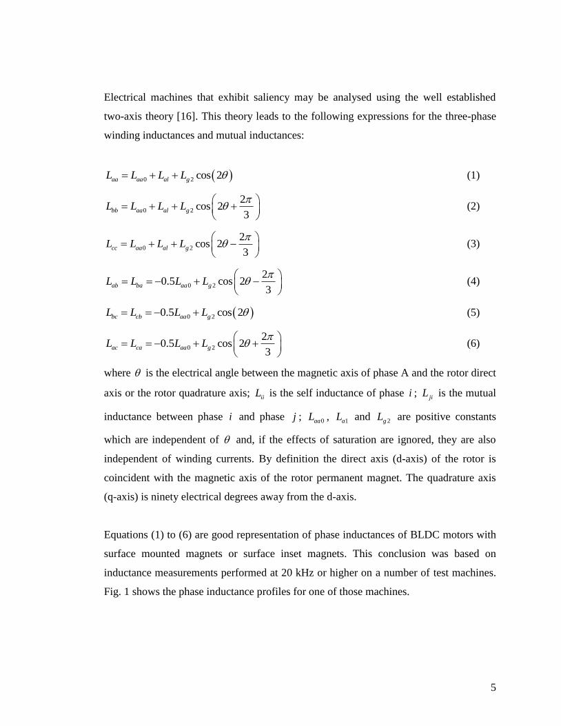
Equations (1) to (6) are good representation of phase inductances of BLDC motors with
surface mounted magnets or surface inset magnets. This conclusion was based on
inductance measurements performed at 20 kHz or higher on a number of test machines.
Fig. 1 shows the phase inductance profiles for one of those machines.
6
It is important to point out that the self-inductances and the mutual inductances that are
referred to here are only effective values rather than actual values. The actual value
of aaL , for example, can only be obtained by measurement if all circuits that are
magnetically linked to phase A were open-circuited. But that is not possible. Whilst the
other two stator windings were open-circuited, the influence of eddy-currents in the
magnets and other parts of the machine could not be eliminated. Thus the measured
winding inductances are lower than their true values. They may be regarded as effective
values that take into consideration the effect of eddy-currents, in a similar manner that
the use of sub-transient inductances in synchronous machine analysis is a way of
accounting for the effect of damper windings and other induced current paths on the
rotor. In the case of the test motors, induced eddy currents in the magnets result in a
lower phase inductance when the magnetic axis of that phase lines up with the magnetic
axis of a rotor magnet (direct axis). Conversely, phase inductance is a maximum when
the magnetic axis of the phase winding lines up with a quadrature axis. Thus the zero
degree position in Fig. 1 or in table 1 corresponds to alignment of the phase A magnetic
axis with the rotor quadrature axis.
The BLDC motor is normally operated with only two phases energised at any one time.
Each phase is energised for a 120 electrical degree interval after which it is de-energised
for a 60 electrical degree interval. The ideal commutation positions,1 to
6 , are shown
in Table 1. These commutation positions lead to the highest electromagnetic torque per
unit ampere as well as the lowest torque ripple. The reason for this is that each phase is
energized during the 120 degree intervals centred about the peak value of the phase back
EMF. There are six distinct commutation intervals. They have been labelled in Fig. 1
according to the phase pair that is energised and supply voltage polarity. For example
CA corresponds to inverter transistors TB+ and TB-, shown in Fig. 2, being kept off and

7
the other four transistors switched so that, on average over a PWM cycle, phase
terminal c is kept at a higher potential relative to phase terminal a.
It follows from the previous paragraph that the zero-crossings of the back EMF of a
particular phase occurs 30 electrical degrees before that phase is energized. But the zero
crossing of the back EMF of a phase winding also coincides with alignment of the
magnetic axis of that winding with the d-axis of the rotor. Clearly at that position the
self-inductance of that phase is a minimum, whereas the inductances of the two other
phases will, because of geometric symmetry, be equal to each other. In other words,
wherever the rotor d-axis aligns with the magnetic axis of the A-phase winding, back
EMF aE is equal to zero and bb ccL L . Similar statements can be made about the B-
phase winding and the C-phase winding. Thus the positions of equal inductance of the
energized phases, just like the zero-crossings of the back EMF of the non-energised
phase occur 30 electrical degrees before the next commutation position.
There are twelve positions of equal inductance over each electrical cycle (360 electrical
degrees). Six of them correspond to the rotor q-axis coinciding with the magnetic axis of
each one of the phase windings. The other six correspond to the rotor d-axis coinciding
with the magnetic axis of each one of the phase windings. Only six of these, the ones
associated with d-axis alignment will be used to help determine commutation positions.
They are specified in Table 1.
3. Detection of Equal Inductance Positions
As mentioned before there are six commutation intervals. During each interval the aim is
to have only two phases active. In Table 1 the six intervals have been labelled according
to the phases that are active. Transition from one interval to the next involves de-
energising of one phase and energising of the next one. This transition is complete only
after the current in the outgoing phase has decayed to zero. Decay of the current occurs
8
through a diode and takes finite time. For example the transition from interval AC to
interval BC involves decaying current through the diode DA-. Therefore each interval
involves two sub-intervals, one during which all three-phase currents are present and one
during which the non-active phase current is equal to zero. In total there are twelve sub-
intervals and twelve corresponding inverter states. The inverter states are labelled
according to the polarity of the DC supply terminal to which the motor phase terminals
are connected. For example inverter state c+a
+ b
- implies the “c” and “a” phase terminals
are connected, through transistors or diodes to the positive DC rail whereas the “b”
terminal is connected to the negative DC rail. Since bipolar PWM is used, during any
one of the commutation intervals, the inverter may be in one of six possible states. For
example during interval AB, the inverter may be in state a+c
+b
-, or a
+c
-b
-, or a
-c
+b
+, or a
-
c-b
+, or a
+b
-, or b
+a
-.
The aim is to use inductive saliency to determine the correct commutation instants for
the motor. The method is based on the sensing of the potential at the non-energised
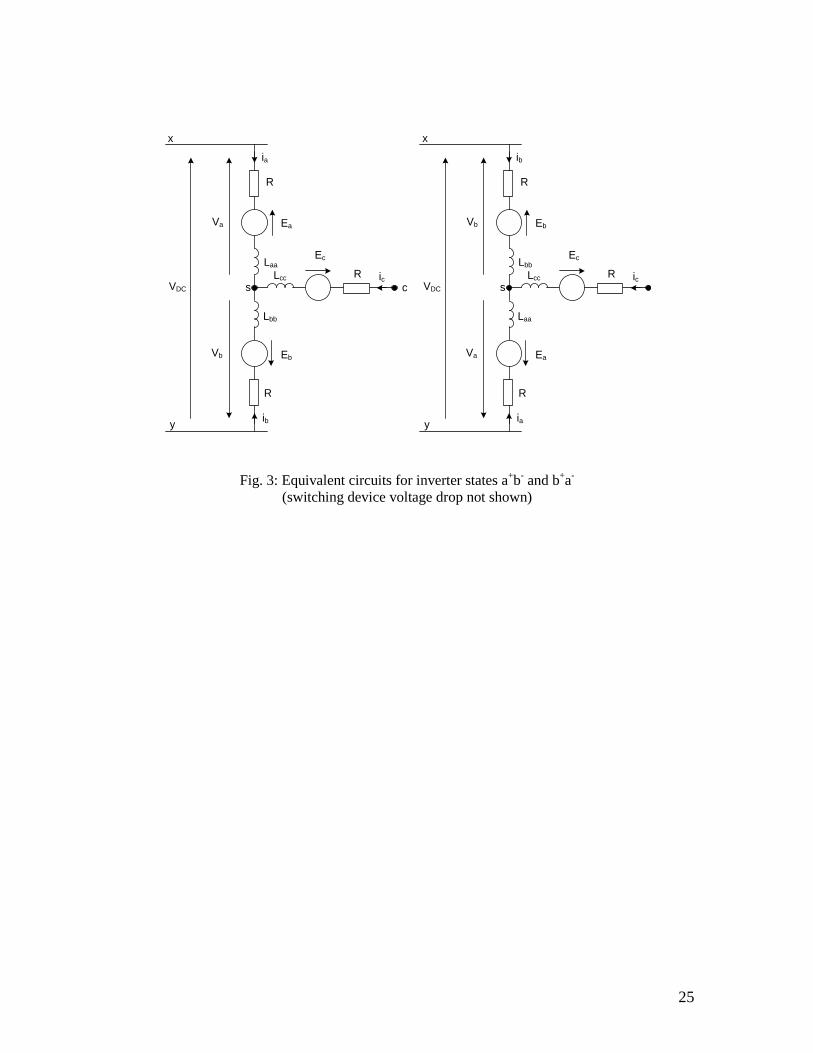
phase winding terminal after the current in that phase has decayed to zero. Consider
commutation interval AB. Assuming current ic has decayed to zero, the inverter will
revert alternately between the states a+b
- and b
+a
-. These are represented by the
equivalent circuits in Fig. 3.
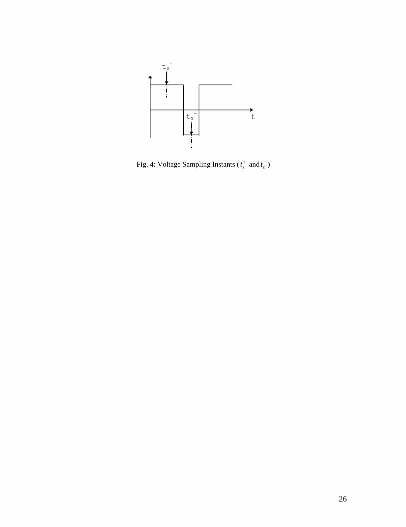
Voltage measurements cyv
and cyv
are carried out while the inverter is respectively in
states a+b
- and b
+a
-. For consistency, as shown in Fig. 4, measurements are carried out
near the middle of the applied voltage pulses. Consecutive measurements cyv
and cyv
are compared. It is shown, in the next paragraphs that those two values are equal to each
other at precisely the position of equal inductance independent of the value of phase
current, supply voltage or speed. Thus, by cyclic monitoring of voltage signals cyv , ayv
9
and byv , commutation instants can be pre-determined with very little computational
effort.
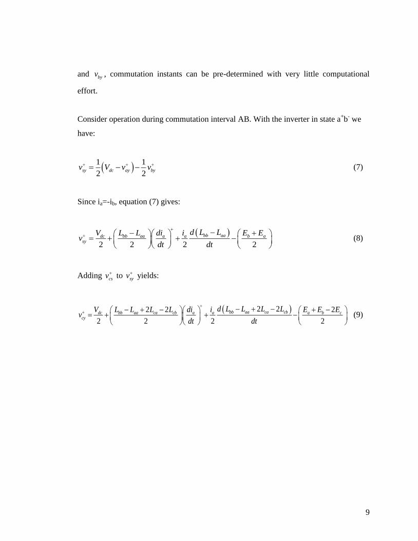
Consider operation during commutation interval AB. With the inverter in state a+b
- we
have:
1 1
2 2sy dc ay byv V v v (7)
Since ia=-ib, equation (7) gives:
2 2 2 2
bb aadc bb aa a a b asy
d L LV L L di i E Ev
dt dt
(8)
Adding csv to syv yields:
2 22 2 2
2 2 2 2
bb aa ca cbdc bb aa ca cb a a a b ccy
d L L L LV L L L L di i E E Ev
dt dt
(9)

10
Also,
22 2
2
aa bb ab
dc a a b t a
a
aa bb ab
d L L LV i E E V i R
dtdi
dt L L L
(10)
where 2 tV is the total switching device voltage drop.
With the inverter in state b+a
- we have:
1 1
2 2sy dc by ayv V v v (11)
Since ia=-ib, equation (11) gives:
2 2 2 2
bb aadc bb aa a a b asy
d L LV L L di i E Ev
dt dt
(12)
Adding csv to syv yields:
2 22 2 2
2 2 2 2
bb aa ca cbdc bb aa ca cb a a a b ccy
d L L L LV L L L L di i E E Ev
dt dt
(13)
Also,
22 2
2
aa bb ab
dc a a b t a
a
aa bb ab
d L L LV i E E V i R
dtdi
dt L L L
(14)
11
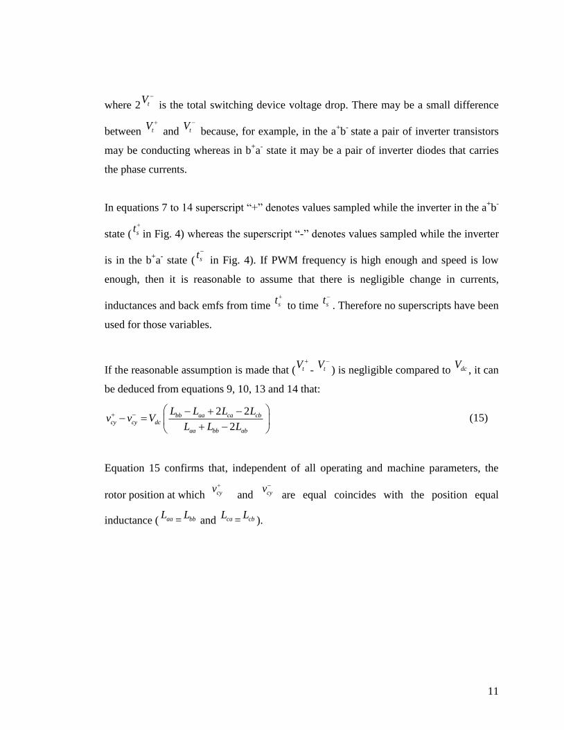
where 2 tV
is the total switching device voltage drop. There may be a small difference
between tV
and tV
because, for example, in the a+b
- state
a pair of inverter transistors
may be conducting whereas in b+a
- state it may be a pair of inverter diodes that carries
the phase currents.
In equations 7 to 14 superscript “+” denotes values sampled while the inverter in the a+b
-
state ( st
in Fig. 4) whereas the superscript “-” denotes values sampled while the inverter
is in the b+a
- state ( st
in Fig. 4). If PWM frequency is high enough and speed is low
enough, then it is reasonable to assume that there is negligible change in currents,
inductances and back emfs from time st
to time st
. Therefore no superscripts have been
used for those variables.
If the reasonable assumption is made that ( tV
- tV
) is negligible compared to dcV, it can
be deduced from equations 9, 10, 13 and 14 that:
2 2
2
bb aa ca cbcy cy dc
aa bb ab
L L L Lv v V
L L L
(15)
Equation 15 confirms that, independent of all operating and machine parameters, the
rotor position at which cyv
and cyv
are equal coincides with the position equal
inductance ( aaL= bbL
and caL= cbL
).

12
Equation 15 may be written as:
5
3 cos 26
( )cos 23
dc q d
cy cy
q d q d
V L L
v v
L L L L
(16)
where:
0 2
3
2q al aa gL L L L (17)
and
0 2
3
2d al aa gL L L L (18)
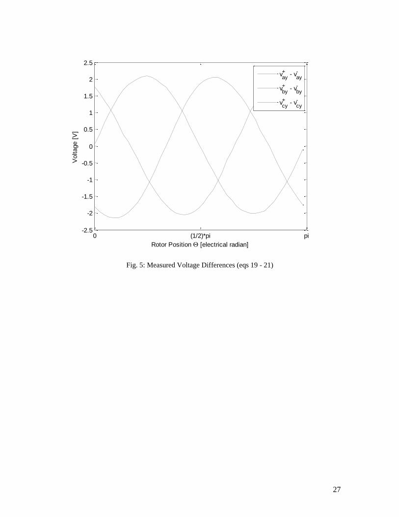
For reasonable saliency ratios, of say less than 1.2, a good approximation for ( cy cyv v )
is:
53 1 cos 2
6
1
dc
cy cy
V S
v vS
(19)
where S is the saliency ratio.
Similarly:
13
3 1 cos 22
1
dc
ay ay
V S
v vS
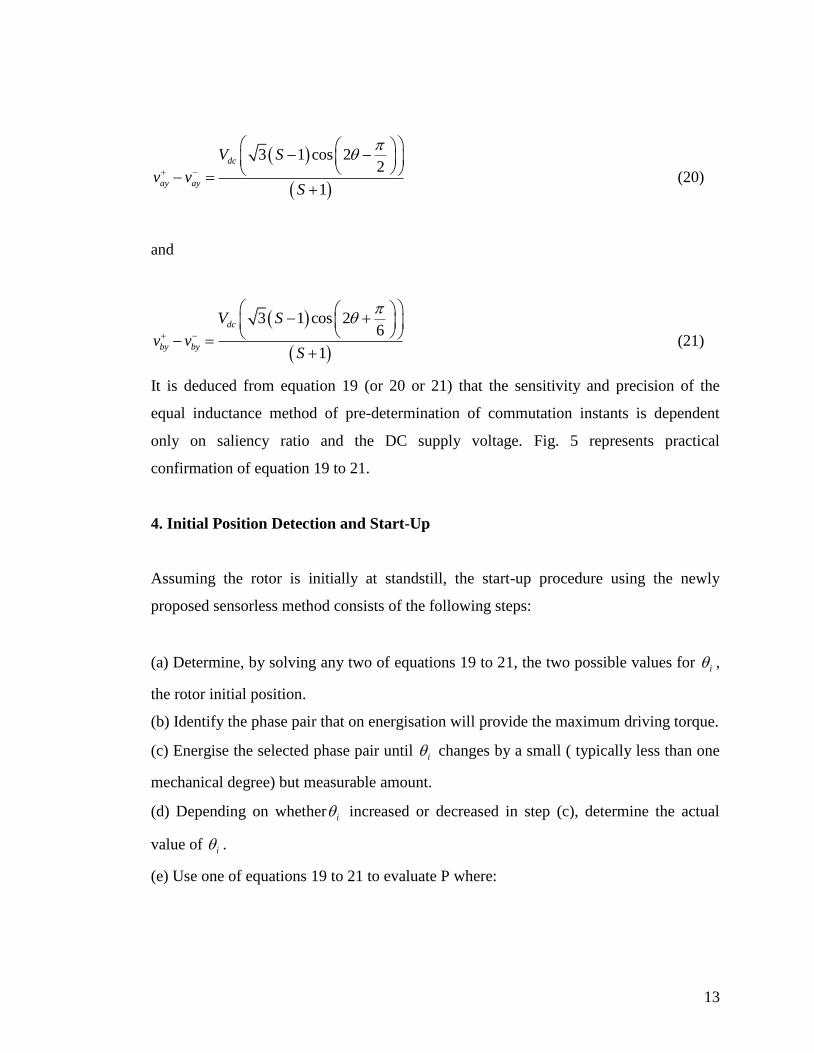
(20)
and
3 1 cos 26
1
dc
by by
V S
v vS
(21)
It is deduced from equation 19 (or 20 or 21) that the sensitivity and precision of the
equal inductance method of pre-determination of commutation instants is dependent
only on saliency ratio and the DC supply voltage. Fig. 5 represents practical
confirmation of equation 19 to 21.
4. Initial Position Detection and Start-Up
Assuming the rotor is initially at standstill, the start-up procedure using the newly
proposed sensorless method consists of the following steps:
(a) Determine, by solving any two of equations 19 to 21, the two possible values for i ,
the rotor initial position.
(b) Identify the phase pair that on energisation will provide the maximum driving torque.
(c) Energise the selected phase pair until i changes by a small ( typically less than one
mechanical degree) but measurable amount.
(d) Depending on whether i increased or decreased in step (c), determine the actual
value of i .
(e) Use one of equations 19 to 21 to evaluate P where:

14
3 1
1
dcV SP
S
(22)
(f) Identify the phase pair and polarity that will provide maximum driving torque for
rotation in the desired direction.
(g) Energise the phase pair identified in step (f) and initiate commutation to the next
phase pair when the value of the measured voltage difference (left hand side of equation
19 or 20 or 21) reaches 3 / 2P .
(h) Activate the normal commutation algorithm straight after initiation of the first
commutation event.
Step (a) requires at least two phase pair energisations to be done with 50 percent PWM
to avoid rotation. Any two or more of the six possible phase pair combinations could be
used. A good strategy would be to use the three pairs and polarities corresponding to
equations 19 to 21 and select two for the determination of i . The third equation can be
used for verification purposes. If, for example, equations 19 and 20 were chosen to
determine the rotor initial position i , then we have:
1tan ( / )d s cP P (23)
where:
1
sin(2 ) 1/ 2 3/ 2
cos(2 ) 1 0
cy cys i
c i ay ay
v vP P
P P v v
(24)
In applying equations 19 to 24 together with measured voltage differences ( cy cyv v ) and
( ay ayv v ), a unique value for d is obtained in the zero to 360 electrical degree range.
The initial rotor position i , however is either equal to / 2d or / 2d plus 180 electrical
degrees. The purpose of steps (b), (c) and (d), listed above, is to determine whether i is
equal to / 2d or to ( 2 ) / 2d . The phase pair combination to be selected in step (b)
should be according to the following:
15
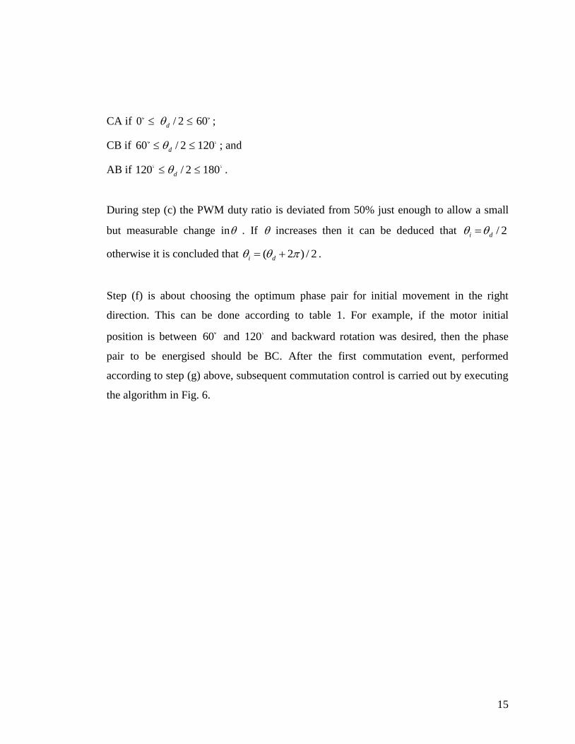
CA if 0 / 2d 60 ;
CB if 60 / 2d 120 ; and
AB if 120 / 2d 180 .
During step (c) the PWM duty ratio is deviated from 50% just enough to allow a small
but measurable change in . If increases then it can be deduced that / 2i d
otherwise it is concluded that ( 2 ) / 2i d .
Step (f) is about choosing the optimum phase pair for initial movement in the right
direction. This can be done according to table 1. For example, if the motor initial
position is between 60 and 120 and backward rotation was desired, then the phase
pair to be energised should be BC. After the first commutation event, performed
according to step (g) above, subsequent commutation control is carried out by executing
the algorithm in Fig. 6.

16
5. Test Results
BLDC commutation based on the equal inductance method was implemented and tested
on a motor whose nameplate data is given in table 2. The commutation algorithm was
implemented using the 56F8013 digital signal controller [17].
As shown in Fig. 7 there is good agreement between the standstill rotor positions
deduced by solving two of equations 19 to 21 and the actual rotor position. This is in
spite of the existence of a small imbalance in phase inductances. The maximum
deviation between actual position and estimated position was found to be 1.4 electrical
degrees.
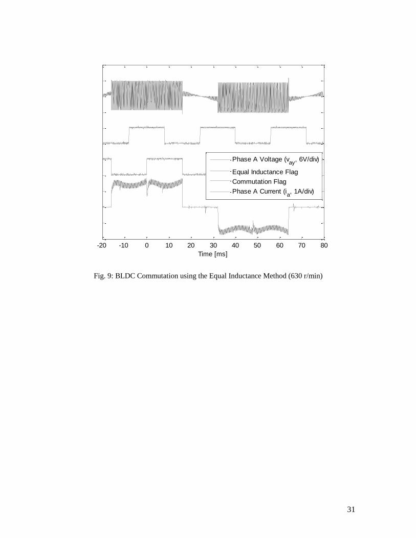
Fig. 8 shows oscillograms of phase A voltage ( ayv ), phase A current, the equal
inductance flag and the commutation flag. The control software operates such that the
equal inductance flag changes state whenever the rotor passes through a position where
the energised phases have equal inductances. Thus, as expected, the equal inductance
flag changes state every 60 electrical degrees. By design the commutation flag lags the
equal inductance flag by 30 electrical degrees. The waveforms in Fig. 8 confirm correct
commutations since commutation events occur every sixty electrical degrees and
disturbance of the non-commutating phase current is small. Fig. 9 confirms that the
equal inductance method works well at higher current and higher speed.
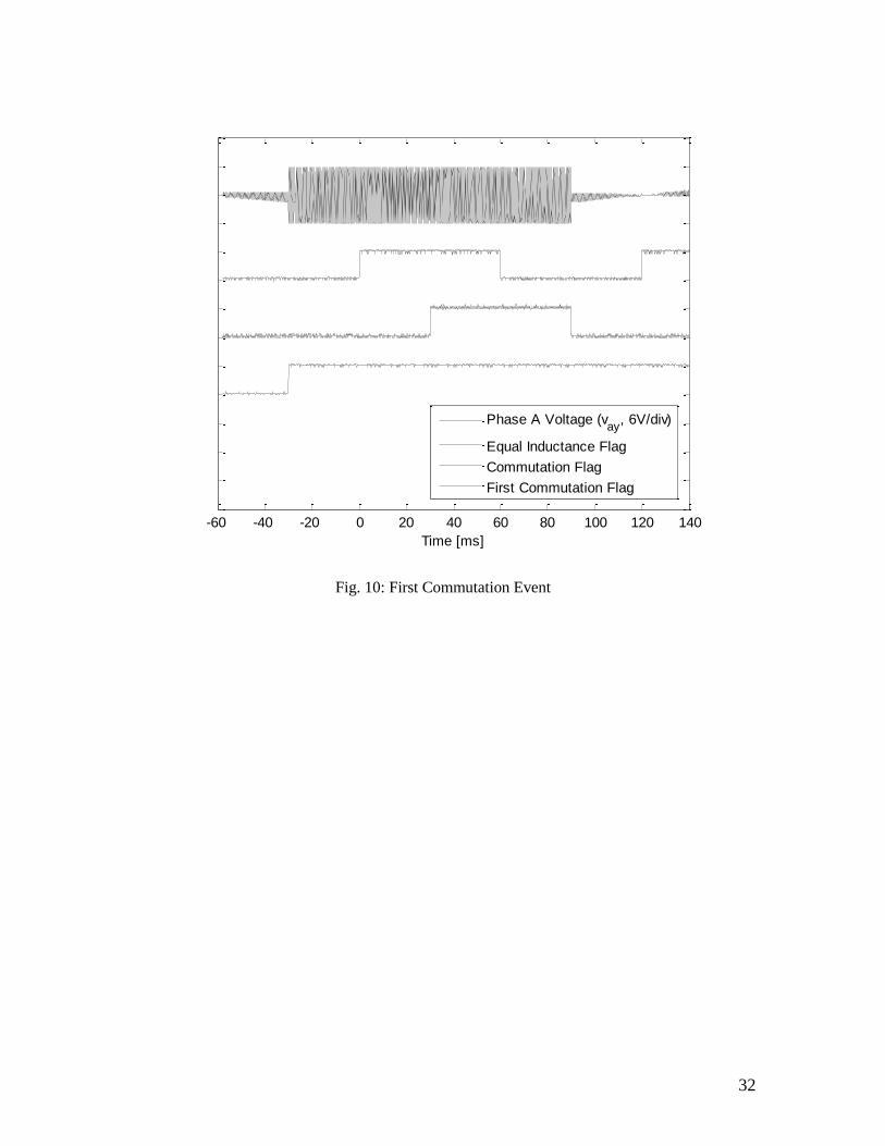
The equal inductance method is used to pre-determine all commutation instants except
the first one. The first commutation flag, displayed in Fig. 10, is set when the voltage
difference (left hand side of equation 19 or 20 or 21) reaches the pre-calculated value
of 3 / 2P . The test results in Fig. 10 confirm correct operation of the proposed starting
17
method since the timing of the instant of the first commutation event determined by the
first commutation flag is consistent with the timing of subsequent commutation event
which are determined by the normal commutation flag.
6. Discussion
Performance of the equal inductance method is best near zero speed since both positive
and negative PWM voltage pulses applied to the active phase pair are relatively wide.
Under those conditions, there is sufficient time for transients to settle before
measurements are made. Also there is sufficient time to perform computations.
However, as speed rises either the positive voltage pulse or the negative pulse within a
PWM cycle becomes shorter and eventually there may not be sufficient time for
transients to settle and for calculations to be performed. Thus there exists an upper limit
of satisfactory performance of the equal inductance method. It is not possible to arrive at
a general conclusion regarding this limit. It depends on supply voltage, saliency,
resolution and speed of the selected digital signal processor and the effect of switching
noise. With a saliency ratio of 1.1 or more, 12V DC supply and a low cost DSP with 8-
bit resolution, it is estimated that performance as good as that obtained with the back
EMF zero crossing is achievable at about 25% of full speed. Well above that speed the
back EMF method is better, whereas well below that speed the equal inductance method
gives superior performance. Thus the equal inductance method complements the back
EMF very well.
The equal inductance method is based on voltage measurements made as voltage pulses
are applied to active winding pairs during bipolar operation. There is no practical
advantage in adapting the method to unipolar operation. With unipolar operation, correct
measurement at very low speed is not possible because the voltage pulse width is too

18
short. Thus adapting the equal inductance method to unipolar operation will not result in
a technique that complements the back EMF zero crossing method. If unipolar operation
is preferred for normal motor operation, it is recommended that the motor is started
under bipolar operation and the equal inductance method up to a minimum speed.
Above that speed, operation can be changed to unipolar with back EMF zero crossings
used to determine commutation instants.
The equal inductance method has been found to perform very well with motors having
surfaced inserted magnets. However, the method can be considered for motors with fully
buried magnets. Qualitative analysis suggests that these motors would exhibit inductive
saliency due to the cumulative effects of rotor geometry and eddy currents induced in
their permanent magnets.
7. Conclusions
A low cost saliency based sensorless technique for BLDC motors has been proposed,
physically implemented and tested. It offers performance that is equal to that obtained
by systems relying on low resolution physical devices such as Hall sensors. Rotor
position is deduced from the response of the BLDC motor un-energised phase terminal
voltage, measured with respect to the negative DC supply rail, due to bipolar PWM
voltage pulses that are normally applied to the other two phases. Theoretical analysis
shows that this potential difference is made up of a DC component equal to the sum of
half the DC supply voltage and the un-energised phase back EMF plus an AC
component (non-sinusoidal) that is modulated by the rotor movement. In other words the
peak to peak value of the AC component varies as rotor position changes. The
fundamental frequency of the AC component is equal to the PWM frequency. It was
found, from the theoretical investigation, that a zero peak to peak value of the AC
component corresponds to a rotor position that is thirty electrical degrees away from the
next ideal commutation position. That rotor position is also the one where the energized

19
phase windings have equal inductances. Hence the adopted sensorless commutation
control method has been termed the „equal inductance method‟. Further theoretical
analysis showed that the peak to peak value of the AC component depends only on the
DC supply voltage and the saliency ratio. In other words the position of equal inductance
deduced from voltage measurements at the un-energised phase terminal is insensitive to
operational parameters such as load current and circuit parameters such as winding
resistance.
It has been demonstrated that with sufficient saliency, standstill rotor position can be
determined from the same measurements made to determine positions of equal
inductance. The necessary phase winding energisations during those measurements may
lead to some back-rotation. But this has been found to be less than a mechanical degree
and is therefore considered negligible. Once the initial rotor position has been
determined, the optimum phase pair to be energised can be selected. Voltage
measurements allow the rotor position for the first commutation event to be identified,
subsequent commutation instants being pre-determined by the „equal inductance
method‟.
The back EMF method of commutation control relies on detection of zero-crossing
instants of the back EMF signal from the unenergised phase. It has been shown that the
instant at which the rotor reaches the equal inductance position coincides with the zero-
crossing instant of the back EMF of the unenergised phase. There is, therefore, a close
parallel between the equal inductance method and the back EMF method. For operation
over a wide speed range it may be advantageous to operate using the equal inductance
method at low speed and the back EMF method at high speed. The close parallel
between the two methods makes it easy to implement changeover strategies from one to
the other as the motor speed crosses the chosen boundary between low speed and high
speed operation.

20
In summary the ‘equal inductance method’ is easy to implement, is very cost
competitive and offers commutation and starting performance equal to that obtained
with Hall sensors. Also, its close parallel with the back EMF method allows seamless
changeover to that method at high speeds.
Acknowledments
The authors would like to acknowledge that this paper reports outcomes of a project that
has been carried out with financial support provided by Metallux SA, Mendrisio,
Switzerland.

21
7. References
[1] Krishnan R.,„Electric motor drives: modelling, analysis and control’, Prentice
Hall, Upper Saddle River, USA, 2001.
[2] Miller T J E.,„Brushless Permanent-Magnet and Reluctance Motor Drive’, Oxford
University Press, Oxford,UK, 1989.
[3] Valentine R. „Motor control electronics handbook’, first edition, McGraw Hill,
Singapore, 1998.
[4] Prokop L, „3-phase BLDC motor control with sensorless back-EMF ADC zero
crossing detection using the 56F805, Designer reference manual’, Motorola Czech
System Laboratories, Roznov pod Radhostem, Czech Republic, 2003
[5] Bolognani S., Oboe R. and Zigliotto M, ‘Sensorless full-digital PMSM drive with
EKF estimation of speed and rotor position’, IEEE Transaction on Industrial
Electronics, Volume 46, Issue 1,1999, pp. 184-191
[6] Kim S. and Sul S, ‘New approach for high-performance PMSM drives without
rotational position sensors’, IEEE Transaction on Power Electronics,Volume 12,
Issue 5, 1997, pp. 904-911
[7] Petrovic V., Stankovic A. and Blasko V, ‘Position estimation in salient PM
synchronous motors based on PWM excitation transients’, IEEE Transaction on
Industry Applications, , Volume 39, Issue 3, 2003, pp. 835-843
[8] Robeischl E. and Schroedl M, ‘Optimized INFORM measurement sequence for
sensorless PM synchronous motor drives with respect to minimum current
distortion’, IEEE Transaction on Industry Applications, , Volume 40, Issue 2, 2004,
pp. 591-598

22
[9] Schmidt P., Gasperi M., Ray, G. and Wijenayake A, ‘Initial rotor angle detection of
a non-salient pole permanent magnet synchronous machine’, IEEE Industry
Applications Society Annual Meeting, New Orleans,1997
[10] Shouse K. and Taylor D, ‘Sensorless velocity control of permanent-magnet
synchronous motors’, IEEE Transaction Control System Technology, Volume 6,
Issue 3,,1998, pp. 313-324
[11] Wang L., Lorenz R.,‘Rotor Position Estimation for Permanent Magnet
Synchronous Motor Using Saliency-Tracking Self-Sensing Method’, Proceedings.of
IEEE IAS Annual Meeting, Rome, Italy, 2000, pp. 445-450
[12] Ueki Y, ‘Detection of relative position between magnetic pole and drive coil in
brushless dc motor’, United State Patent, Patent Number 5,159,246,1992
[13] Weiss W,‘Artificial heart with sensorless motor’, United State Patent, Patent
Number 5,751,125, 1998
[14] Ahfock A., and Gambetta D., „Technique for Sensorless Commutation of Brushless
DC Motors ‟, Swiss Institute of Intellectual Property, Bern, Patent Application
Number 00342/05, 2005.
[15] Gambetta D., „Sensorless Technique for BLDC Motors‟, MPhil Dissertation,
University of Southern Queensland, Australia, 2006
[16] Fitzgerald, A., Kingsley, C. and Umans, S, Electric machinery, sixth edition,
McGraw Hill, Singapore, 2003
[17] Freescale Semiconductor, 56F8000 16-bit digital signal controller peripheral
reference manual, rev 0, 2005, Freescale Semiconductor Literature Distribution
Center, Denver, USA

23
0 (1/2)*pi pi (3/2)*pi 2*pi180
185
190
195
200
205
210
Rotor Position [el. rad]
Self I
nducta
nces [
uH
]
Laa
Lbb
Lcc
Fig. 1: Measured Self-Inductances

24
DA+TA
+
TA- DA
-DB
-
DB+
DC+
DC-
x
y
a
b
c
s
ia
ic
vc vb va
TB+
TB-
TC+
TC-
ib
Fig. 2: Inverter Bridge Supplying a Brushless DC Motor
25
Laa
Lbb
s
x
y
Ea
Eb
R
R
ia
ib
Va
Vb
VDC
Lbb
Laa
s
x
y
Eb
Ea
R
R
ib
ia
Vb
Va
VDC
Lcc
Ec
R icc
Lcc
Ec
R ic
Fig. 3: Equivalent circuits for inverter states a
+b
- and b
+a
-
(switching device voltage drop not shown)
26
Fig. 4: Voltage Sampling Instants ( st
and st
)
t
ts+
ts-
27
0 (1/2)*pi pi-2.5
-2
-1.5
-1
-0.5
0
0.5
1
1.5
2
2.5
Rotor Position [electrical radian]
Voltage [
V]
v+ay
- v-ay
v+by
- v-by
v+cy
- v-cy
Fig. 5: Measured Voltage Differences (eqs 19 - 21)

28
Begin
Calculate P using eq 19 or 20 or 21
Inductance difference for first
commutation reached?
Initial position estimation as per step (a) to (d) section 4
Commutation timer reached 2x?
Start rotation as per steps (f) and (g) section 4
Perform next commutation
Reset commutation timer
yes
Equal inductance position reached?
Store time (x) elapsed between previous commutation
and equal inductance instant
yes
no
no
no
yes
Fig. 6: Commutation Algorithm Based on the Equal Inductance Method

29
0 pi 2*pi 3*pi 4*pi 5*pi 6*pi 7*pi 8*pi-1
0
1
2
3
4
5
6
7
Actual Position [electrical radian]
Estim
ate
d P
ositio
n
[ele
ctr
ical ra
dia
n]
Actual Position
Estimated Position
Fig. 7: Comparison between Actual and Estimated Rotor Position (360 Mechanical)

30
-80 -40 0 40 80 120 160 200 240 280 320
Time [ms]
Phase A Voltage (vay
, 6V/div)
Equal Inductance Flag
Commutation Flag
Phase A Current (ia, 1A/div)
Fig. 8: BLDC Commutation using the Equal Inductance Method (139 r/min)
31
-20 -10 0 10 20 30 40 50 60 70 80
Time [ms]
Phase A Voltage (vay
, 6V/div)
Equal Inductance Flag
Commutation Flag
Phase A Current (ia, 1A/div)
Fig. 9: BLDC Commutation using the Equal Inductance Method (630 r/min)
32
-60 -40 -20 0 20 40 60 80 100 120 140
Time [ms]
Phase A Voltage (vay
, 6V/div)
Equal Inductance Flag
Commutation Flag
First Commutation Flag
Fig. 10: First Commutation Event

33
Table 1: Equal Inductance Positions and Commutation Intervals
Rotor position range (electrical degrees) 0 to
60
60
to
120
120
to
180
180
to
240
240
to
240
300
to
360
Energised pair in each commutation
interval
CA CB AB AC BC BA
Equal inductance position before next
commutation event 30 90 150 210 270 330
Next commutation position
1
60
2
120
3
180
4
240
5
300
6
360

34
Table 2: Test Motor Details
Rated Voltage (V) 12
Rated Current (A) 2
Rated Speed (rpm) 2400
Number of Poles 8