A New Old Approach to Teaching Microprocessors: Update … · A New Old Approach to Teaching...
8
A New Old Approach to Teaching Microprocessors: Update and Lessons Learned Abstract In 2009 we described a hands-on approach to teaching microprocessors in which students hand- wired a Z80-based microprocessor system and programmed it in machine code. The construction of the microprocessor system was accompanied by lectures in a variety of topics including computer organization, instruction set architectures, the Intel family of microprocessors, and high-speed techniques such as pipelining and superscalar processing. The course has now been taught twice and undergone a number of modifications to both the content and the Z80 system built by the students. In this paper we report on those modifications and lessons learned. In addition, we describe three student projects that were based on the Z80 system. Introduction Undergraduate courses in microprocessors are typically based on simple training kits or simulators based on processors such as the 6800 or 8085 connected to system components such as memory, clock, etc. 1 In these courses, the internal architecture as well as the remaining system components and interconnects (memory, clocks, buses, etc.) were described conceptually and the emphasis, in terms of the hardware usage, was on learning and using the instruction set and interfacing peripheral devices. Since those early times, microprocessor technology has progressed to the point that a trainer employing a Pentium or Core 2 device would essentially comprise a stand-alone computer. This leaves the instructor with the choice of either using a simpler trainer or using the students’ laptop or desktop itself as the trainer and teaching an extremely complex instruction set. In either case, the microprocessor’s internal architecture and external interconnects are reduced to abstractions and the study of microprocessors to a study of assembler instructions and interfacing. A third approach, intended to give the students a more “hands-on” experience, involves the students constructing a complete system from discrete building blocks or programmable components such as FPGAs. In 2000, Jeon described a course in which each student constructed and programmed an 8086-based microcomputer. 2 This approach eliminates many of the “black box” aspects of the conventional microprocessor course and gives the students some of the hands-on experience of the third approach. In 2009 we described a new course that combines many aspects and advantages of the older approaches described above. 3 As such, it constitutes a “new old” approach to teaching microprocessors. In this course the students begin by constructing several of the internal components of the CPU, such as a two-bit adder and two’s complement engine, to gain hands-on understanding of these components. Next, each student constructs a simple memory bus using three-state drivers. Finally, the students construct simple clock and control circuits and add the microprocessor to form a complete microcomputer system. A Z80 was selected for the CPU rather than an 8086 for several reasons. First and foremost, the 8086 is no longer manufactured. Second, the Z80’s clock is DC-coupled, allowing students to single-step through instructions for debugging (the 8086 requires a 2 MHz minimum clock speed). Third, the Z80 is a popular processor among hobbyists and in industry and is supported by a rich set of peripheral interface
Transcript of A New Old Approach to Teaching Microprocessors: Update … · A New Old Approach to Teaching...
A New Old Approach to Teaching Microprocessors: Update and Lessons Learned
Abstract In 2009 we described a hands-on approach to teaching microprocessors in which students hand-wired a Z80-based microprocessor system and programmed it in machine code. The construction of the microprocessor system was accompanied by lectures in a variety of topics including computer organization, instruction set architectures, the Intel family of microprocessors, and high-speed techniques such as pipelining and superscalar processing. The course has now been taught twice and undergone a number of modifications to both the content and the Z80 system built by the students. In this paper we report on those modifications and lessons learned. In addition, we describe three student projects that were based on the Z80 system. Introduction
Undergraduate courses in microprocessors are typically based on simple training kits or simulators based on processors such as the 6800 or 8085 connected to system components such as memory, clock, etc.1 In these courses, the internal architecture as well as the remaining system components and interconnects (memory, clocks, buses, etc.) were described conceptually and the emphasis, in terms of the hardware usage, was on learning and using the instruction set and interfacing peripheral devices. Since those early times, microprocessor technology has progressed to the point that a trainer employing a Pentium or Core 2 device would essentially comprise a stand-alone computer. This leaves the instructor with the choice of either using a simpler trainer or using the students’ laptop or desktop itself as the trainer and teaching an extremely complex instruction set. In either case, the microprocessor’s internal architecture and external interconnects are reduced to abstractions and the study of microprocessors to a study of assembler instructions and interfacing. A third approach, intended to give the students a more “hands-on” experience, involves the students constructing a complete system from discrete building blocks or programmable components such as FPGAs. In 2000, Jeon described a course in which each student constructed and programmed an 8086-based microcomputer.2 This approach eliminates many of the “black box” aspects of the conventional microprocessor course and gives the students some of the hands-on experience of the third approach. In 2009 we described a new course that combines many aspects and advantages of the older approaches described above.3 As such, it constitutes a “new old” approach to teaching microprocessors. In this course the students begin by constructing several of the internal components of the CPU, such as a two-bit adder and two’s complement engine, to gain hands-on understanding of these components. Next, each student constructs a simple memory bus using three-state drivers. Finally, the students construct simple clock and control circuits and add the microprocessor to form a complete microcomputer system. A Z80 was selected for the CPU rather than an 8086 for several reasons. First and foremost, the 8086 is no longer manufactured. Second, the Z80’s clock is DC-coupled, allowing students to single-step through instructions for debugging (the 8086 requires a 2 MHz minimum clock speed). Third, the Z80 is a popular processor among hobbyists and in industry and is supported by a rich set of peripheral interface
components and projects. Fourth, the Z80 provides completely independent data and address buses; on the 8086, the lower eight bits of the address bus are multiplexed with the data bus, which students can find confusing. In addition, since the Z80 is based on the 8080, Z80 instructions are very similar to basic x86 instructions. As an added benefit, the memory addressing on the Z80 is much simpler than x86-family addressing; the Z80 uses a flat memory model as opposed to the more confusing segment-plus-offset model used by x86 architecture CPUs. Since 2009 the course has been taught twice and a number of changes have been made to the course content and schedule. In this paper we describe the changes and lessons learned. We also describe three student projects that were developed as part of the course. Course Description The microprocessor course is required for students in the Electrical Engineering Technology concentration. The objectives of the course are to:
1. Explain basic microprocessor and microcomputer organization 2. Explain the programming model and instruction set architecture of modern
microprocessors 3. Build and program a simple microcomputer system 4. Interface basic I/O components to a microcomputer 5. Understand advanced microprocessor concepts such as pipelining, superscalar
processing, and the Core 2 architecture These objectives are achieved through a combination of lectures, outside (primarily web-based) reading assignments, hands-on laboratory exercises, and the construction of the Z80-based microcomputer. The course is offered in an 11-week quarter term format. The course begins with a conventional introduction to microprocessors, including such topics as history of microprocessors, internal organization, and common microprocessor families. Next, programming in assembly is discussed and the students learn to program both in x86 and Z80 assembly. This is followed by a midterm exam. In the original version of the course, the microprocessor system was constructed using wirewrap technology due to its relative durability and reliability. In addition, the students wired the full 16-bit address bus. In practice, this was found to be extremely time consuming, using most of the latter part of the term. To avoid this problem two modifications were made to the original computer system. First, it was decided to migrate to a breadboard-based design using PB-505 Workstations from Global Specialties (or the functionally equivalent CADET II Trainers from E&L), designed for use in basic analog and digital courses.4,5 These trainers avoided the need for wirewrapping switches and displays. The resulting systems were found to be as reliable as the original wirewrap versions and could be fabricated in much less time. Second, it was decided to wire up only the low 8 bits of the address bus. This supports programs up to 256 bytes in length
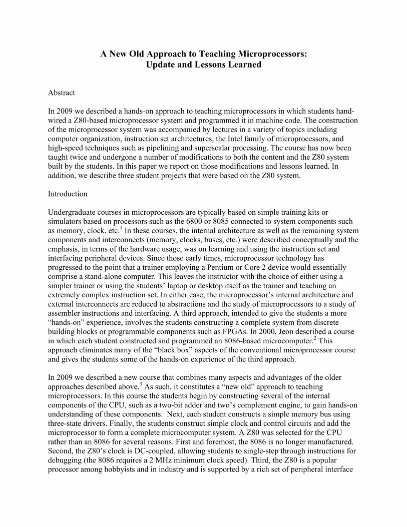
but, again, was found to substantially shorten fabrication time. The breadboarded version of the new design is shown in Figure 1.
Figure 1. Breadboarded version of the Z80 microcontroller system.
As a result of these changes the students were able to fabricate and debug their systems about four weeks earlier than with the original version. This freed up the second part of the course for student projects. Table 1 shows the new course schedule. The students presented their projects during the 11th week of the course.
Week Topic
1 Introduction to microprocessors, number systems 2 Generic programming model, Instruction set architectures, program
execution 3 Assembly language 4 Program control instructions, arithmetic and logic instructions 5 Exam 6 Pipelined execution 7 Superscalar execution 8 Pentium/Core Duo architecture, cache memory 9 Z80 projects 10 Z80 projects 11 Presentations
Table 1. Revised course topics by week.

In the following sections we describe three of the most interesting and challenging projects. Student Project 1: The Well-tempered Z80 (a Z80 music box) The process of synthesizing music directly from a microprocessor usually involves external circuitry such as a Digital-to-Analog converter (DAC). The idea for this project was to produce music directly from the Z80 bus using solely the Z80 computer and an external speaker to play the notes. The Z80 basically acts as a very limited DAC, in that it can output various frequencies but only with 1 bit resolution, limiting the output to a square wave. These frequencies can be changed programmatically and strung together in sequence to produce various songs, allowing the Z80 to play music. In fact, the 8-bit, trainer-based Z80 system was used largely unmodified: a 4MHz TTL oscillator replaced the trainer’s onboard clock circuitry, and a small speaker was tied directly to the A15 address line. The music generation was implemented purely in software. In order to create a proof-of-concept music box capable of playing simple melodies, two things are required—a method of accurately reproducing the correct frequency for each note, and a scheme to play the correct sequence of notes. To ensure that notes sound correct, the frequency must be within roughly 0.5% of the correct value. Concert pitch “A4” is defined as 440 Hz; the frequency ratio between two musical notes is given as 2(n/12), where n is the number of musical half-steps between the notes. To create the frequencies for the notes, a two-part timing routine was written, with an inner and outer delay loop. The desired period for each note is calculated from its frequency; since the delay time for the timing routine can be easily calculated (Eq. 1), the correct timing parameters for each note can be determined. With a clock speed of 4 MHz and a two-part timing loop, note that frequencies were produced that were well within the required limits of precision (5 musical cents) to sound on-key. (Table 2) ! = 2× # !""!" !""#$×! !"#"$!
!!"# (1)
Table 2. Frequencies and closest Z80 equivalents.
In order to get the Z80 to produce musical tones from the delay loops, a programming trick was used. Since an pure 8-bit address bus is used for this course, memory addresses “wrap around” every 256 bytes. If a command were issued to access memory location 0x8127, for example, this

would result in a read to memory location 0x27 (since only 256 bytes are used.) This leaves the extra eight address lines essentially free, since they do not affect program execution. The A15 address line (the MSB of the address bus) was tied to the speaker. To bring the output signal high for half of the loop, the program jumped to 0x8085 (actual memory location 0x85), driving A15 high. To bring the output low for the second half of the loop, the program jumped back to memory location 0x0075 (actual memory location 0x75), bringing the A15 line low. One of the challenges the students encountered involved the Z80’s built-in memory refresh circuitry. Because the Z80 is designed to work with dynamic memory (DRAM), it has a built-in memory refresh cycle – which can’t be disabled. One of the side effects is to periodically place the refresh register onto the high byte of the address bus. Because of this, the timing loops had to not only count correctly, but continually update the refresh register with 0x00 (for the low half of the cycle) or 0x80 (for the high half). The system with 4 MHz oscillator is shown in Figure 2.
Figure 2. The Z80, slightly modified with a 4MHz oscillator and a speaker.
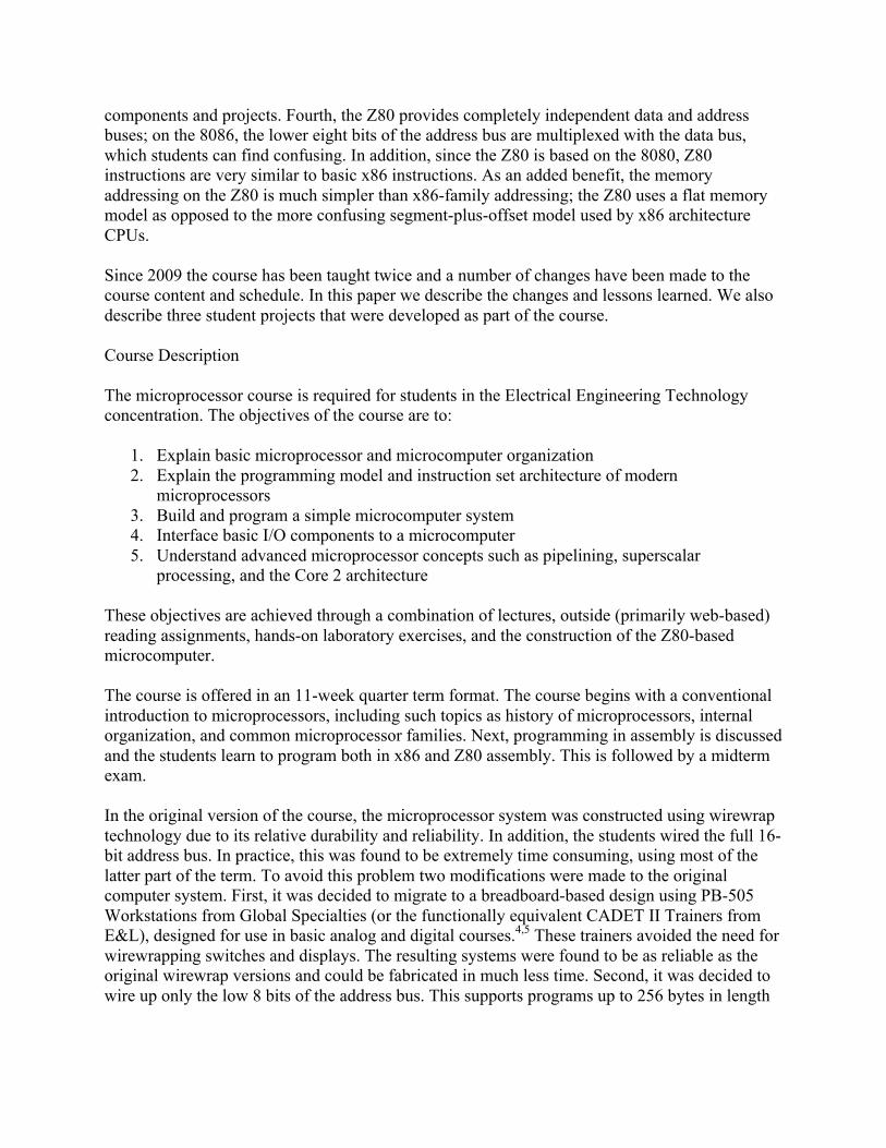
Student Project 2: LabVIEW-based Z80 programmer As the student teams progressed from having built and tested their Z80 computers to programming them, a few limitations became apparent. One of these was due to the nature of the way the Z80 computers are programmed in the current system: a set of eight SPST toggle switches on the trainer is used to load a pair of register chips, which are then used to program the address and data buses of the computer. While this setup helps facilitate a good understanding of the organization of a Z80-based microcomputer, it can make entering Z80 programs of significant size somewhat tedious. Furthermore, the programs are entered into RAM, and so are lost every time the system is shut down. One team decided to build a programmer to automate as much of the programming task as possible, allowing students to enter Z80 machine code via a PC. Two National Instruments DAQ units (USB-6501 USB Digital I/O Device6) connect to the Z80 hardware; in conjunction with a LabVIEW-based interface, the DAQs handle the Z80 bus requests and programming tasks,
allowing individual memory locations to be read and written. Although the current iteration of the Z80 system is a pure 8-bit design, the Z80 Programmer team opted to use a 15-bit address bus on their programmer, allowing the entire 32KB address space of the CY7C199P SRAM chip to be accessed. Because of the functionality afforded by a PC-based programming scheme such as this, much of the original Z80 design is no longer needed. Specifically, as can be seen in Figure 3 below, the address and data bus latch chips, as well as most of the combinatorial control logic, is no longer needed; the DAQs handle the control lines directly, including coordinating bus operations with the Z80 CPU via the ~BUSRQ and ~BUSAK lines. The LabVIEW interface (Figure 4) is straightforward: the address and data busses are shown on the left. Individual memory locations can be read and written using the GUI, as the students demonstrated during their in-class presentation. Further enhancement of this design is quite feasible—since LabVIEW can read from comma-delimited and other similar text files on the PC, it would be possible to develop this prototype into a fully-automatic programmer/debugger system.
Figure 3. The LabVIEW-based programmer setup. The two DAQs are stacked together and secured with duct tape.
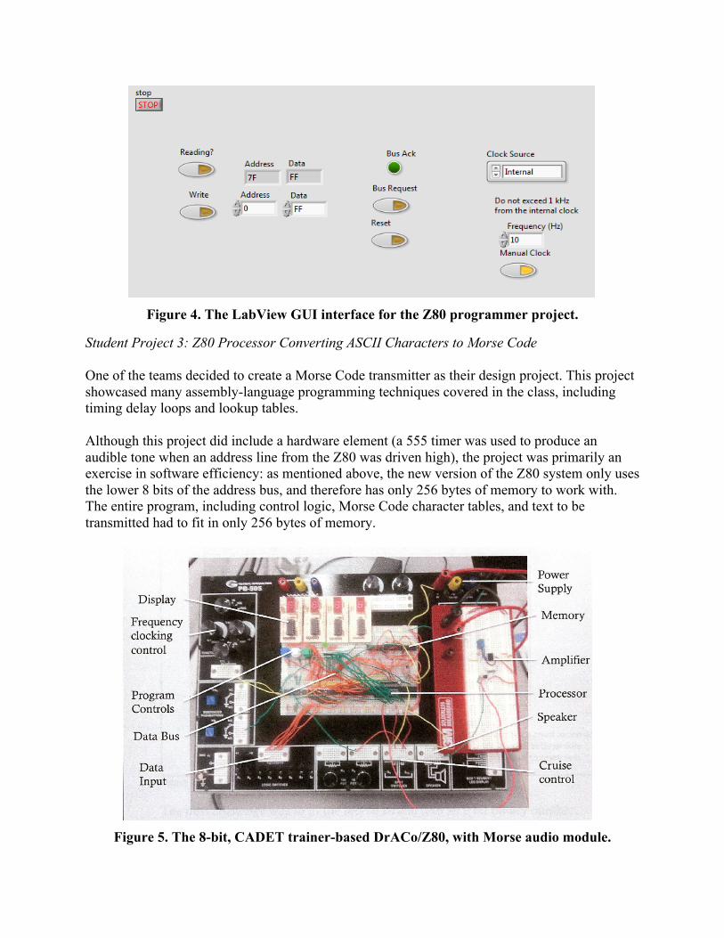
Figure 4. The LabView GUI interface for the Z80 programmer project.
Student Project 3: Z80 Processor Converting ASCII Characters to Morse Code One of the teams decided to create a Morse Code transmitter as their design project. This project showcased many assembly-language programming techniques covered in the class, including timing delay loops and lookup tables. Although this project did include a hardware element (a 555 timer was used to produce an audible tone when an address line from the Z80 was driven high), the project was primarily an exercise in software efficiency: as mentioned above, the new version of the Z80 system only uses the lower 8 bits of the address bus, and therefore has only 256 bytes of memory to work with. The entire program, including control logic, Morse Code character tables, and text to be transmitted had to fit in only 256 bytes of memory.
Figure 5. The 8-bit, CADET trainer-based DrACo/Z80, with Morse audio module.

The Morse Code transmitter, shown in Figure 5, works as follows: A lookup table of ASCII text to be sent is parsed, one character at a time. This text is then translated, character by character, into specialized bytes which directly represent the Morse Code elements to be sent; each translated byte contains five element bits (zero for “dot” and one for “dash”), as well as a three-bit length field, to allow for the varying length of Morse code characters. In this implementation, the most-significant five bits are used to store the Morse elements in left-to-right order, while the least-significant three bits are used to store the length of the character. The length field is used to initialize an element counter, and the element bits are then left-shifted one by one into the Z80’s Carry bit. For example, the letter “E” would be represented as 0XXXX001 (with X standing for a don’t-care.) The least-significant three bits instruct the program that this character has only one Morse element; the MSB denotes that this bit is a dot. Similarly, the character “4” would be represented as 00001101. This lookup scheme works for any characters with one through five elements, meaning all letters and numbers can be represented. However, punctuation is not covered, since these characters are typically six elements long in Morse Code. A character-specific lookup scheme would be needed to enable encoding of these. Figure 6 shows the representation of several code characters.
Figure 6. Representation of various Morse Code characters in one bit per character.
Conclusions This paper described our experiences and lessons learned during the development of a new hands-on course in microprocessors. The course is built around a Z80 microprocessor-based computer system built by the students during the course of the class. Several modifications were made to the course since its inception. In particular, the microprocessor system was migrated from its original wirewrap version to a breadboard-based design. Second, only the low 8 bits of the address bus were wired. The time saved by these modifications was used by the students to develop a number of interesting Z80-based projects, three of which were presented in this paper. Reference 1. See, e.g., http://ieeexplore.ieee.org/stamp/stamp.jsp?arnumber=00572896. Last accessed 3/6/12. 2. Jeon, J. W. (2000). “A Microprocessor Course: Designing and Implementing Personal Microcomputers.” IEEE
Transactions on Education. 43, 426-433. 3. Rosen, W. A. and Carr, M.E. “A New Old Approach to Teaching Microprocessors.” DVD Proceedings ASEE
Middle Atlantic Section Spring Conference 2009, April 24-25, 2009, Baltimore, MD 4. http://www.globalspecialties.com/electronic-trainers/analog-a-digital-circuit-design-workstation/item/100-pb-
505.html. Last accessed 3/6/12. 5. http://www.techedu.com/EL_CADET2.asp. Last accessed 3/6/12. 6. http://sine.ni.com/nips/cds/view/p/lang/en/nid/201630. Last accessed 3/6/12.