A New Method to Analyse the Mechanical Behaviour of ...
18
A new method to analyse the mechanical behaviour of skeletal parts Citation for published version (APA): Brekelmans, W. A. M., Poort, H. W., & Slooff, T. J. J. H. (1972). A new method to analyse the mechanical behaviour of skeletal parts. Acta Orthopaedica Scandinavica, 43(5), 301-317. https://doi.org/10.3109/17453677208998949 DOI: 10.3109/17453677208998949 Document status and date: Published: 01/01/1972 Document Version: Publisher’s PDF, also known as Version of Record (includes final page, issue and volume numbers) Please check the document version of this publication: • A submitted manuscript is the version of the article upon submission and before peer-review. There can be important differences between the submitted version and the official published version of record. People interested in the research are advised to contact the author for the final version of the publication, or visit the DOI to the publisher's website. • The final author version and the galley proof are versions of the publication after peer review. • The final published version features the final layout of the paper including the volume, issue and page numbers. Link to publication General rights Copyright and moral rights for the publications made accessible in the public portal are retained by the authors and/or other copyright owners and it is a condition of accessing publications that users recognise and abide by the legal requirements associated with these rights. • Users may download and print one copy of any publication from the public portal for the purpose of private study or research. • You may not further distribute the material or use it for any profit-making activity or commercial gain • You may freely distribute the URL identifying the publication in the public portal. If the publication is distributed under the terms of Article 25fa of the Dutch Copyright Act, indicated by the “Taverne” license above, please follow below link for the End User Agreement: www.tue.nl/taverne Take down policy If you believe that this document breaches copyright please contact us at: [email protected] providing details and we will investigate your claim. Download date: 12. Feb. 2022
Transcript of A New Method to Analyse the Mechanical Behaviour of ...

A new method to analyse the mechanical behaviour of skeletalpartsCitation for published version (APA):Brekelmans, W. A. M., Poort, H. W., & Slooff, T. J. J. H. (1972). A new method to analyse the mechanicalbehaviour of skeletal parts. Acta Orthopaedica Scandinavica, 43(5), 301-317.https://doi.org/10.3109/17453677208998949
DOI:10.3109/17453677208998949
Document status and date:Published: 01/01/1972
Document Version:Publisher’s PDF, also known as Version of Record (includes final page, issue and volume numbers)
Please check the document version of this publication:
• A submitted manuscript is the version of the article upon submission and before peer-review. There can beimportant differences between the submitted version and the official published version of record. Peopleinterested in the research are advised to contact the author for the final version of the publication, or visit theDOI to the publisher's website.• The final author version and the galley proof are versions of the publication after peer review.• The final published version features the final layout of the paper including the volume, issue and pagenumbers.Link to publication
General rightsCopyright and moral rights for the publications made accessible in the public portal are retained by the authors and/or other copyright ownersand it is a condition of accessing publications that users recognise and abide by the legal requirements associated with these rights.
• Users may download and print one copy of any publication from the public portal for the purpose of private study or research. • You may not further distribute the material or use it for any profit-making activity or commercial gain • You may freely distribute the URL identifying the publication in the public portal.
If the publication is distributed under the terms of Article 25fa of the Dutch Copyright Act, indicated by the “Taverne” license above, pleasefollow below link for the End User Agreement:www.tue.nl/taverne
Take down policyIf you believe that this document breaches copyright please contact us at:[email protected] details and we will investigate your claim.
Download date: 12. Feb. 2022

Acta orthop. Scandinav. 43,301-317,1972
A NEW METHOD TO ANALYSE THE MECHANICAL BEHAVIOUR OF SKELETAL PARTS
W. A. M. BREKELMANS, H. W. POORT & T. J. J. H. SLOOFF
Accepted 6. iv. 72
For orthopaedic interventions and studies it is of importance to acquire a sound understanding of the mechanical behaviour of skeletal parts under various physiological loads. This makes it possible to estimate the effects of operations and substitutions, and to predict behaviour under extreme conditions. Moreover, criteria can be estab- lished which substitutes and osteosynthesis material should fulfil in mechanical terms. For the prediction of the mechanical behaviour of a given skeletal part, this paper will outline a way to design a model of this part which approximates reality as closely as possible. This means that the model must account for the essential parameters of behaviour.
This study intends to demonstrate that a mathematical model designed on the basis of the finite element method is to be preferred to existing techniques of studying the mechanical behaviour of skeletal parts. A number of load situations will be analysed with reference to a two-dimensional model of a femur. A number of results obtained with this mathematical model will be presented. Before discussing the mathematical model, available possibilities will be reviewed.
R E S E A R C H P O S S I B I L I T I E S
The mechanical behaviour of bone can be studied by means of ( 1 ) ex- perimental techniques and ( 2 ) mathematical models.
This paper was prepared in collaboration with the Eindhoven Research Group on Bio-Mechanics. The participants in this Research Group are: H. M. Berntsen, 0. S. Ingwersen (Diaconessenziekenhuis, Eindhoven) ; G. Chapchal, T. J. J. H. Slooff (Catholic University, Nijmegen); W. A. M. Brekelmans, J. D. Janssen, H. W. Poort, P. P. T. G. van Rens, A. G. Sanders, L. B. M. Tomesen and S. D. Zorge (University of Technology, Eindhoven).
20 ACTA ORTH. 43, 5
Act
a O
rtho
p D
ownl
oade
d fr
om in
form
ahea
lthca
re.c
om b
y T
echn
isch
e U
nive
rsite
it E
indh
oven
on
10/1
7/14
For
pers
onal
use
onl
y.
302 W. A. M. BREKELMANS ET AL.
Experimental Techniques The experimental techniques most commonly used so far to
measure stress and strain situations in a given loading case can be divided into two types: ( 1 ) direct methods and (2) methods using a material model.
Methods of the first type include the brittle coating technique, the optical method, and the strain-gauge measurements. Those of the second type include the photo-elastic technique.
Brittle coating technique: A coating of varnish is applied to the bone surface. Cracks and tears occur in such coating during loading, and conclusions on the magnitude of strain in the underlying material of the object can be deduced from these cracks and tears.
The results thus obtained are inaccurate, incomplete and qualitative. Another disadvantage is that the results are strongly influenced by changes in the temperature and humidity of the bone material. This technique was used in particular during the period 1940-1960 (Evans 1948, Lissner 1948, Pedersen 1949, Hayes 1953, Powers 1953).
Optical method (photo-stress technique) : The bone is first sprayed with reflecting paint, followed by a coat of birefringent plastic mate- rial. The bone is then subjected to a load and with the aid of polarized light, coloured patterns appear, distinguishable as isoclinics and fringes. Isoclinics are lines connecting points with a constant principal direc- tion of stress. Fringes are lines connecting points with a constant dif- ference between the principal stresses.
The principal disadvantage of this difficult technique is that the measuring accuracy is limited; one of the reasons for this is the dif- ference in thickness of the layer of optical material.
Accuracy is also affected by the ill-defined shape of the bone exam- ined. Studies of this type have been made by Rabischong (1964), Leduc (1966) and Blaimont-Wagner (1965).
Strain-gauge measurements: Strain-gauges are glued to the bone surface. In a given load situation the change of the electric resistance with respect to the unloaded situation is measured and the strains at certain sites on the external surface can be accurately determined. The disadvantage of this method is that, i f carried out properly, it is very elaborate and time-consuming (Blaimont 1968, Slooff 1970).
An advantage of the above-mentioned methods is that they account for the material properties of the bone. A joint disadvantage of these methods is that information on the strain situation is obtained only at the bone surface.
Act
a O
rtho
p D
ownl
oade
d fr
om in
form
ahea
lthca
re.c
om b
y T
echn
isch
e U
nive
rsite
it E
indh
oven
on
10/1
7/14
For
pers
onal
use
onl
y.
MECHANICAL REHAVIOUR OF SKELETAL PARTS 303
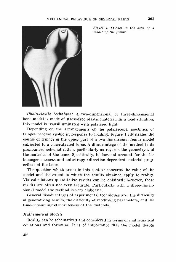
Figure 1 . Fringes in the head of a model of the f emur .
Photo-elastic technique: A two-dimensional or three-dimensional bone model is made of stress-free plastic material. In a load situation, this model is transilluminated with polarized light.
Depending on the arrangements of the polariscope, isoclinics or fringes become visible in response to loading. Figure 1 illustrates the course of fringes in the upper part of a two-dimensional femur model subjected to a concentratcd force. A disadvantage of the method is its pronounced schematization, particularly as regards the geometry and the material of the bone. Specifically, it does not account for the in- homogeneousness and anisotropy (direction-dependent material prop- erties) of the bone.
The question which arises in this context concerns the value of the model and the extent to which the results obtained apply to reality. Via calculations quantitative results can be obtained : however, these results are often not very accurate. Particularly with a three-dimen- sional model the method is very elaborate.
General disadvantages of experimental techniques are : the difficulty of generalizing results, the difficulty of modifying parameters, and the time-consuming elaborateness of the methods.
Mathematical Models Reality can be schematized and considered in terms of mathematical
equations and formulae. It is of importance that the model design
20'
Act
a O
rtho
p D
ownl
oade
d fr
om in
form
ahea
lthca
re.c
om b
y T
echn
isch
e U
nive
rsite
it E
indh
oven
on
10/1
7/14
For
pers
onal
use
onl
y.

304 W. A. M. BREKELMANS ET AL.
should account for the essential parameters. Such a model should adequately describe reality and it should be possible to verify this. The model should be verifiable or falsifiable with the aid of an experi- ment in reality (the purpose of such an experiment differs funda- mentally from the purpose of experiments as listed in the previous section).
As long as it can be demonstrated that the model adequately de- scribes reality, the advantages of this method are that parameters can be modified without difficulty, the information obtained is more extensive, and the results can be generalized.
M A T H E M A T I C A L M O D E L
When analysing a construction, we distinguish: (1) mechanical system, characterized by: ( a ) geometry and ( b ) material properties; ( 2 ) load- ing; (3 ) prediction of mechanical behaviour.
Schematic representation :
-+ mechanical behaviour geometry material
In order to make a statement on mechanical behaviour data on loading, geometry and material properties must be available. In addi- tion, one must have access to a theory or analytical technique by which the mechanical system can be described. These requirements merit a separate discussion with specific reference to skeletal parts.
Material, Loading and Geometry Experiments to determine the physical properties of bone have been
carried out by such investigators as Glasser (1947), Evans & Lebow ( 1959), Smith & Walmsley (1960), Hirsch (1958), Sedlin (19661, Semb (1966), Comtet-Dunoyer-Vassal & Arene (1967), Blaimont & Burny (1968), Halleux & Jedwab (1968), and Da Silva (1970). They determined such properties as the tensile strength, compressive strength hardness and Young’s modulus of bone material.
A comparison of the values reported by different authors for the same physical magnitude reveals considerable differences. In many cases the techniques used are not specified, and it is therefore dif-
Act
a O
rtho
p D
ownl
oade
d fr
om in
form
ahea
lthca
re.c
om b
y T
echn
isch
e U
nive
rsite
it E
indh
oven
on
10/1
7/14
For
pers
onal
use
onl
y.

MECHANICAL BEHAVIOUR OF SKELETAL PARTS 305
ficult to evaluate the data reported. These data must therefore be used with prudence.
Roughly the same applies to load situations. Publications on load situations (Rydell 1966, hlcLeish & Charnley 1970, J. P. Paul 1971) report rather diverse values.
Determinations of the geometry of skeletal parts are currently being made with the aid of radioplanigraphy at the Eindhoven University of Technology.
Model Design on a Mathematical Basis Analytical m e t h o d : Mathematical model design for determination
of mechanical behaviour has often made use in the past of classical analytical theories (for the femur Koch 1917, Blaimont 1968, and others). A simplified model is set up in that case in order to determine mechanical magnitudes. However, the use of existing theories leads to a number of complications which necessitate introduction of exces- sive simplifications in the mathematical model, so that its practical value becomes questionable.
The actual causes of these complications are to be found in the fol- lowing aspects :
1. It is difficult to give an analytical description of the geometry of skeletal parts.
2. The real load situations are too complicated to be imitated. 3. Application of the analytical method cannot account for the
physical prcjperties of the bone material (anisotropy, inhomo- geneousness) .
Fini te e lement -method: At this time there are computer-orientated techniques in mechanics which afford a much better chance of success. They make it possible to account, in the model, for geometry, material properties and load situations. The principal difficulty now lies in the choice of data to be introduced for this purpose. The finite element- method will be discussed in detail in the following sections, with reference to a femur model.
E L U C I D A T I O N O F T H E F I N I T E E L E M E N T - M E T H O D
For simplicity the methodology of this new computing procedure will be outlined on the basis of a two-dimensional, flat, homogeneous and
Act
a O
rtho
p D
ownl
oade
d fr
om in
form
ahea
lthca
re.c
om b
y T
echn
isch
e U
nive
rsite
it E
indh
oven
on
10/1
7/14
For
pers
onal
use
onl
y.

306 W. A. M. BREKELMANS ET AL.
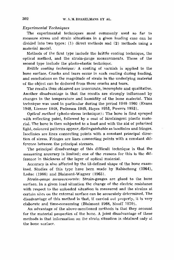
Figure 2. Example o f distribution of elements.
isotropic model of a femur. In principle, a two-dimensional model of this kind is identical to the model used in the photo-elastic technique. The femur was chosen because: (1) it is an important weight-bearing part of the body; (2 ) it is a unit which can be isolated fairly well; (3) it is a relatively simple skeletal part; (4 ) it is a skeletal part in which fractures and substitutions are not entirely unproblematic; (5) it is currently a focus of interest in the literature on theoretical and experi- mental investigations ; this affords a possibility of comparing results.
For the finite element method, the model of the object to be studied is divided into a large number of elements with simple delimitations (e.g. triangles or rectangles for the two-dimensional model, tetra-
Act
a O
rtho
p D
ownl
oade
d fr
om in
form
ahea
lthca
re.c
om b
y T
echn
isch
e U
nive
rsite
it E
indh
oven
on
10/1
7/14
For
pers
onal
use
onl
y.

MECHANICAL BEHAVIOUR OF SKELETAL PARTS 307
hedrons or prisms for the three-dimensional model; Figure 2 ) . To each separate element physical properties could be adjusted, which could be different from element to element.
A two-dimensional femur model is divided into a number of, say, triangular elements which are numbered 1 through m. All nodal points (the angular points of the elements) are numbered 1 through n. Fig- ure 2 gives an example of such a division in which m = 224 and n = 146.
The mechanical properties of such an element are less complex than those of the object in its entirety, with its random geometry. The ap- propriate junction of the elements makes it possible to reach conclu- sions on the mechanical properties of the entire object.
As a result of such a method of computation, we can expect numer- ical data on such aspects as: (1) the displacements at each nodal point; ( 2 ) the strains of each element; ( 3 ) the stresses in each element: ( 4 ) possibly the principal stresses, the principal direction of stress and the equivalent stress for each element.
The following may be said about the equivalent stress. Three-dimen- sionally the stress state at a given site is determined by six magnitudes (by three magnitudes when two-dimensionally seen). It is customary in technology to combine these six (or three) magnitudes in a single figure : the so-called equivalent stress. This single figure characterizes the local sensitiveness for the accessory loading case, to derive from the stress state on the basis of a certain criterion.
A well-tested criterion in mechanics for homogeneous, isotropic, tough materials is that of Maxwell, Huber & Heneky. This criterion is used in this paper to determine the equivalent stress.
1000 N A z A
- X
860
Figure 3. A . Situation of loading according to Koch (1917). B. Situation of loading according to Rude11 (1966) and McLeish & Charnlev (1970).
Act
a O
rtho
p D
ownl
oade
d fr
om in
form
ahea
lthca
re.c
om b
y T
echn
isch
e U
nive
rsite
it E
indh
oven
on
10/1
7/14
For
pers
onal
use
onl
y.

308 W. A. M. BREKELMANS ET AL.
Figure 4 . The division of elements m = n =
936. 537.
Q U A N T I T A T I V E D A T A O N T H E M O D E L C H O S E N
A two-dimensional model of a femur with an external geometry, as described by Koch (1917), will now be analysed in two different load situations :
a. A loading such as that used by Koch, i.e. a force which acts upon the femoral head along a line which connects the centre of the head with a point halfway between the medial and the lateral condyle.
b. A loading such as that indicated by Rydell (1966), in which a force is directed at the centre of the femoral head (with a point of application within an area he outlined on the head) combined with
Act
a O
rtho
p D
ownl
oade
d fr
om in
form
ahea
lthca
re.c
om b
y T
echn
isch
e U
nive
rsite
it E
indh
oven
on
10/1
7/14
For
pers
onal
use
onl
y.

MECHANICAL BEHAVIOUR OF SKELETAL PARTS 309
Figure 5 . A . Deformed a n d undeformed situation during loading according to Koch (1917).
Figure 5 . B . Deformed and undeformed situation during loading according f o Rude11 (1966) and McLeish & CharnleJj (1970).
another force (McLeish & Charnley 1970) at the greater trochanter, in a direction as indicated by Rydell (the direction of the resultant of the abductor muscles).
With the former loading, the magnitude of the force is of no interest in view of the linearity of the theory. With the latter loading, only the proportion between the two forces is of importance. For both loading cases, the supporting, the fixation of the bone with the rigid
Act
a O
rtho
p D
ownl
oade
d fr
om in
form
ahea
lthca
re.c
om b
y T
echn
isch
e U
nive
rsite
it E
indh
oven
on
10/1
7/14
For
pers
onal
use
onl
y.

310 W. A. M. BREKELMANS ET AL.
Figure 6 . A . Stress in direction during loading Koch (1917).
longitudinal according to
Figure 6 . B. Stress in longifudinal direction during loading according to Rydell (1966) and McLeish h Charnley (1970).
environment, is the same. The bone is imagined as being clamped fast along its entire underside. This means that for the displacements of all points of the edge of the medial and the lateral condyle, we have assumed a specified value equal to zero.
Act
a O
rtho
p D
ownl
oade
d fr
om in
form
ahea
lthca
re.c
om b
y T
echn
isch
e U
nive
rsite
it E
indh
oven
on
10/1
7/14
For
pers
onal
use
onl
y.

MECHANICAL BEHAVIOUR OF SKELETAL PARTS 31 1
'"7
Figure 7 . Main stresses during according to Koch (1917):
negative principal stress of
posit ive principal stress of 1 N/mm2.
I N/mmz.
loading
30
30
Figure 8. Main stresses during loading according to Rydell (1966) and McLeish & Charnley (1970):
negative principal stress of 30
posit ive principal stress of 30 1 N/mmz.
N/mmz.
Figure 3 illustrates the Although not essential to tions :
load situations to be analysed for this bone. the method, we made the following restric-
1. We assumed the material at the time to be homogeneous, iso- tropic and linear with: Young's modulus: E = 20,000 N/mm2. Poisson's ratio : v = 0.37.
Act
a O
rtho
p D
ownl
oade
d fr
om in
form
ahea
lthca
re.c
om b
y T
echn
isch
e U
nive
rsite
it E
indh
oven
on
10/1
7/14
For
pers
onal
use
onl
y.

312 W. A. M. BREKELMANS ET AL.
2. We assumed the thickness of the model to be constant. The numerical value we assign to this thickness is not important because, given the linearity of the theory, the results to be ob- tained for displacements, strains and stresses are inversely pro- portional to the thickness. We chose a thickness of 10 mm.
The dimensions in the plane of Figure 4 are taken identical with those indicated by Koch, i.e. true size. The model is divided into 936 elements and 537 nodal points are created. Figure 4 illustrates this division.
For making such a division and for the corresponding data, an element generator has been developed which greatly reduces the amount of manual work involved.
After computer analysis we primarily obtain the displacements of the nodal points. Figure 5 shows the undeformed as well as the de- formed contour of the external circumference; for the sake of con- venience, a factor of magnification has been applied to the displace- ments. We used a scale for the external circumference: 1: 4.25; a scale for the displacements: 1 : 0.85.
This means that the factor of magnification applied to the displace- ments had the value 5. The fields of displacement for the two load situations prove to be hardly different. From these displacements,
lO0Ol 1200/
Figure 9. A . Trajectories of stress during loading according to Koch (1917). B. Trajectories of stress during loading according to Rydell (1966) and McLeish
& Charnleg (1970).
Act
a O
rtho
p D
ownl
oade
d fr
om in
form
ahea
lthca
re.c
om b
y T
echn
isch
e U
nive
rsite
it E
indh
oven
on
10/1
7/14
For
pers
onal
use
onl
y.

MECHANICAL BEHAVIOUR OF SKELETAL PARTS 313
Figure 10. A . Equivalent stresses dur- ing loading according to Koch (1917) .
, i I I
'4.L. Figure 10. B. Eqt l i r~a~ent stresses dur- ing loading according to Rgdell (1966) and McLeish & Charnleg (1970) .
strains and stresses in each element are determined with the aid of the computer.
These stresses could be presented in tabulated form or as figures written in the elements in a figure such as Figure 4. A more per-
Act
a O
rtho
p D
ownl
oade
d fr
om in
form
ahea
lthca
re.c
om b
y T
echn
isch
e U
nive
rsite
it E
indh
oven
on
10/1
7/14
For
pers
onal
use
onl
y.
314 W. A. M. BREKELMANS ET AL.
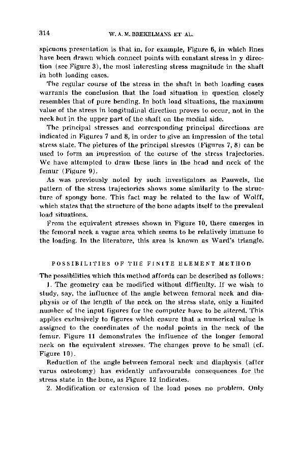
spicuous presentation is that in, for example, Figure 6, in which lines have been drawn which connect points with constant stress in y direc- tion (see Figure 3 ) , the most interesting stress magnitude in the shaft in both loading cases.
The regular course of the stress in the shaft in both loading cases warrants the conclusion that the load situation in question closely resembles that of pure bending. In both load situations, the maximum value of the stress in longitudinal direction proves to occur, not in the neck but in the upper part of the shaft on the medial side.
The principal stresses and corresponding principal directions are indicated in Figures 7 and 8, in order to give an impression of the total stress state. The pictures of the principal stresses (Figures 7, 8) can be used to form an impression of the course of the stress trajectories. We have attempted to draw these lines in the head and neck of the femur (Figure 9 ) .
As was previously noted by such investigators as Pauwels, the pattern of the stress trajectories shows some similarity to the struc- ture of spongy bone. This fact may be related to the law of Wolff, which states that the structure of the bone adapts itself to the prevalent load situations.
From the equivaient stresses shown in Figure 10, there emerges in the femoral neck a vague area which seems to be relatively immune to the loading. In the literature, this area is known as Ward’s triangle.
P O S S I B I L I T I E S O F T H E F I N I T E E L E M E N T M E T H O D
The possibilities which this method affords can be described as follows: 1. The geometry can be modified without difficulty. If we wish to
study, say, the influence of the angle between femoral neck and dia- physis or of the length of the neck on the stress state, only a limited number of the input figures for the computer have to be altered. This applies exclusively to figures which ensure that a numerical value is assigned to the coordinates of the nodal points in the neck of the femur. Figure 11 demonstrates the influence of the longer femoral neck on the equivalent stresses. The changes prove to be small (cf. Figure 1 0 ) .
Reduction of the angle between femoral neck and diaphysis (after varus osteotomy ) has evidently unfavourable consequences for the stress state in the bone, as Figure 12 indicates.
2. Modification or extension of the load poses no problem. Only
Act
a O
rtho
p D
ownl
oade
d fr
om in
form
ahea
lthca
re.c
om b
y T
echn
isch
e U
nive
rsite
it E
indh
oven
on
10/1
7/14
For
pers
onal
use
onl
y.

MECHANICAL BEHAVIOUR OF SKELETAL PARTS 315
Figure 1 1 . Equivalent stresses in a model w i th elongation o f fhe collum.
'\
I I I ,/' I
.. .
Figure 12. Equivalent stresses in a model af ter oarus osteofomg of the collum.
a few of the input figures for the computer have to be altered. The principle problem lies in determining the magnitude and direction of the most interesting loads.
Act
a O
rtho
p D
ownl
oade
d fr
om in
form
ahea
lthca
re.c
om b
y T
echn
isch
e U
nive
rsite
it E
indh
oven
on
10/1
7/14
For
pers
onal
use
onl
y.
316 W. A. M. BREKELMANS ET AL.
3. The model can be expanded to three dimensions. It is also possible to account for the anisotropy and inhomogeneity of the bone material in the model. These expansions of the model pose no fundamental problems. Again the complication lies in the question: which data are to be introduced into the model? 4. The effect of substitutions and osteosynthesis material on
mechanical behaviour can be studied in the model. A comparison of these possibilities with those afforded by the experi-
mental techniques or classical analytical theories is clearly in favour of the analysis with the aid of the finite element method.
S U M M A R Y
This contribution to the analysis of stresses and strains in a skeletal part is based on the finite element method. Efforts are made to demon- strate that this method is suitable par exceZZence for analysis of com- plex constructions such as the femur. The procedure is explained with reference to a simple two-dimensional model. The results obtained in a few load situations are presented in various ways.
It is demonstrated that the complex geometry and the variety of load situations pose no problems in analysis by this method.
With this paper we had no intention of going into the subject of the theoretical formulation of the method.
R E F E R E N C E S
Blaimont, P. & Wagner, J. (1965) Preliminaires B 1’6tude biomechanique de la prothbse d’Austin Moore. Aeta chir. belg. 54, 829-840.
Blaimont, P. & Burny, F. (1968) Resistance B la traction et duret6 de Ia diafyse femoral. Acta orthop. belg. 34, 883-892.
Blaimont, P., Halleux, P. & Jedwab, J. (1968) Distribution des contraintes osseuses dans le femur. Reu Chir. orthop. 54, 303-319.
Comtet, J. J., Rozier, F., Vassal, R., Arbne, J. M. & Fisscher, L. (1967) Reeherches ex- perimentales sur la resistance de la diafyse des 0s longs chez l’homme. Rev. Chir. orthop. 53, 3-17.
DaSilva,O. (1970) The physical properties of the cortical neck of the femur. Acta orthop. seand. 40, 729-756.
Evans, F. G. & Lissner, H. R. (1948) Stresscoat deformation studies of the femur under static vertical loading. Anat. Rec. 100, 190-200.
Evans, F. G., Lissner, H. R. & Pedersen, H. E. (1948 b) Deformation studies of the femur under dynamic vertical loading. Anat. Rec. 101, 225-245.
Evans, F. G., Hayes, J. F. & Powers, J. E. (1953) Stresscoat deformation studies of the human femur under transverse loading. Anat. Rec. 116, 171-184.
Act
a O
rtho
p D
ownl
oade
d fr
om in
form
ahea
lthca
re.c
om b
y T
echn
isch
e U
nive
rsite
it E
indh
oven
on
10/1
7/14
For
pers
onal
use
onl
y.

MECHANICAL BEHAVIOUR OF SKELETAL PARTS 31 7
Evans, F. G. (1969) The mechanical properties of bone. Art i f . Limbs 13, 1-17. Frocht, M. M. (1957) Photoelasticity. J. Wiley & Sons, New York. Glasser, 0. (1947) Medical phrjsics. The Year Book Publishers Inc., Chicago. Hirsch, C. & Brodetti, A. (1958) Methods of studying some mechanical properties
Hirsch, E. C. & Frankel, V. H. (1960) Analyses of forces producing fractures on the
Koch, J. C. (1917) t a w s of bone architecture. Amer. J. Anat. 21, 177-298. Leduc, A. (1966) Contribution expCrimentale A 1’6tude biomkchanique du femur
McLeish,R.D. & Charnley, J. (1970) Abduction forces in the one legged stance.
Milch,H. (1940) Photoelastic studies on bone. J . Bone J t Surg. 22, 621-635. Paul, J. P. (1971) Load actions on the femur in walking and some resultant stresses.
Rabischong, P. & Avril, J. (1965) R61e biomechanique des poutres composites os-
Rydell, M. (1966) Forces acting on the femoral head. Acta orthop. scand. 88-96. Sedlin, E. & Hirsch, G. (1966) Factors affecting the determination of the physical
Semb, H. (1966) The breaking strength of normal and immobilized cortical bone
Slooff, T. J. J. H. (1970) The influence of acrgllic cement on the f i za t ion of the
Smith, J. W. & Walmsley, R. (1959) Factors affecting the clasticity of bone. J. Anat.
Williams, J. F. & Svensson, N. L. (1968) A force analysis of the hip joint. Bio-med.
of hone tissue. Acta orthop. scand. 28, 1-11.
proximal end of the femur. J. Bone J t Surg. 42-B, 633-640.
(thtse). Universite Libre Bruxelles.
J. Biomechanics 3, 191-209.
E z p . Mech. 11, 121-125.
muscles. Reu. Chir. orthop. 51, 437-458.
properties of femoral cortical bone. Acta orthop. scand. 37, 29-48.
from dogs. Acta orthop. scand. 37, 131-140.
hipendoprosthesis. Thoben Offsett Drukkery, Nijmegen.
(Land.) 93, 503-523.
Engng. 3, 365-370.
Correspondence to :
Dr. T. J. Slooff Katholieke Universiteit St. Iladboud Ziekenhuis Nijmegen Netherlands
21 ACTA OATH. 43, 5
Act
a O
rtho
p D
ownl
oade
d fr
om in
form
ahea
lthca
re.c
om b
y T
echn
isch
e U
nive
rsite
it E
indh
oven
on
10/1
7/14
For
pers
onal
use
onl
y.
![[Owen] Mechanical Behaviour of the.](https://static.fdocuments.us/doc/165x107/577cd7161a28ab9e789e04ab/owen-mechanical-behaviour-of-the.jpg)