A new manipulator structure for power-assist...
18
A new manipulator structure for power-assist devices P. Gonzalez de Santos, E. Garcia, J.F. Sarria, R. Ponticelli and J. Reviejo Department of Automatic Control Institute of Industrial Automation – CSIC 28500 Arganda del Rey, Madrid, Spain [email protected] Abstract: Purpose – This paper introduces a new manipulator structure to configure power-assist devices in order to protect operators from musculoskeletal disorders. The mechanical structure and the control system are presented, along with their main features. Design/methodology/approach – The new structure is designed under the criterion of minimizing the torques required for handling payloads of up to 75 kg in an easily controlled system. Findings – A new structure is provided, based on electrical AC motors and capable of handling high payloads yet exerting low motor torque. Originality/value – The application of the criterion of minimizing the required torques to handle heavy payloads produced a new manipulator structure. This structure is patent protected. Keywords – Robotics, Power-assist devices, Easy handling. Paper type – Research paper 1. Introduction Handling of heavy loads is a main concern in industry. Load mishandling causes lower back disorders in workers and a large number of accidents, especially in small and medium enterprises, where workers are liable to undergo more accidents and injuries. Loads are sometimes light enough for workers to lift, but because they have to be lifted very frequently, fatigue and, in the worst of cases, injury may easily result. According to the European Agency for Safety and Health at Work (OSHA, 2009), around 30% of European workers suffer back injuries caused by the physical effort involved in lifting and handling loads, repetitive movements or the need to maintain a particular posture. As a result, EU labour legislation is restricting the loads that can be directly handled by workers. In the naval industry, for example, there is now a 25-kg
Transcript of A new manipulator structure for power-assist...

A new manipulator structure for power-assist devices
P. Gonzalez de Santos, E. Garcia, J.F. Sarria, R. Ponticelli and J. Reviejo
Department of Automatic Control Institute of Industrial Automation – CSIC 28500 Arganda del Rey, Madrid, Spain
Abstract:
Purpose – This paper introduces a new manipulator structure to configure power-assist
devices in order to protect operators from musculoskeletal disorders. The
mechanical structure and the control system are presented, along with their main
features.
Design/methodology/approach – The new structure is designed under the criterion of
minimizing the torques required for handling payloads of up to 75 kg in an
easily controlled system.
Findings – A new structure is provided, based on electrical AC motors and capable of
handling high payloads yet exerting low motor torque.
Originality/value – The application of the criterion of minimizing the required torques
to handle heavy payloads produced a new manipulator structure. This structure is patent
protected.
Keywords – Robotics, Power-assist devices, Easy handling.
Paper type – Research paper
1. Introduction
Handling of heavy loads is a main concern in industry. Load mishandling causes
lower back disorders in workers and a large number of accidents, especially in small
and medium enterprises, where workers are liable to undergo more accidents and
injuries. Loads are sometimes light enough for workers to lift, but because they have to
be lifted very frequently, fatigue and, in the worst of cases, injury may easily result.
According to the European Agency for Safety and Health at Work (OSHA, 2009),
around 30% of European workers suffer back injuries caused by the physical effort
involved in lifting and handling loads, repetitive movements or the need to maintain a
particular posture. As a result, EU labour legislation is restricting the loads that can be
directly handled by workers. In the naval industry, for example, there is now a 25-kg
limit on the loads that can be directly handled by one operator, and the sectors that
support the construction industry are reducing the weight of their products (such as bags
of cement). This legislative trend, combined with safety-at-work recommendations, is
now making it necessary for tools and handling-support systems to be used whenever
loads exceed legal limits.
Various tools to aid in handling (power-assist devices, PADs) have been designed
and marketed with a view to solving this problem, using gravity compensation and load
counter-weighting with limited degrees of freedom. These conventional devices are
operated either directly by the operator or by means of very primitive interfaces, and,
while they have had a positive impact on working conditions for operators, they have
not improved the precision with which items can be positioned or the way in which
items can be guided, nor have they increased functionality in unusual situations or
interaction with the user. Furthermore, their use is not intuitive; they offer but poor
reactive response and no inertia control. This means that the operator tends to have to
move the load back and forth over the intended position in a series of corrective moves,
a circumstance that can lead to muscle fatigue and loss of concentration, which clearly
alters working routines and therefore productivity.
Power-assist devices have been designed and marketed, based on passive movement
mechanisms (Delnondedieu and Trocazz, 1995) and/or gravity-compensation elements.
These simple systems really only help to support the weight of the object in question
and lead to serious problems in terms of controlling inertia (decelerating or braking the
load), following a particular trajectory or arriving at a relatively precise position.
In the mid-1990s, a group of engineers and researchers at Northwestern University,
NU (IL, USA), and the University of California at Berkeley, UCB, using specifications
from the automotive industry and the OSHA (Occupational Safety and Health
Administration, USA), suggested using computer-controlled technology to improve the
capacities of people working with PADs. They coined the term “intelligent assist
devices” (IADs) (Book et al., 1996) to describe mechanisms displaying some very
important potential features for power assistance, guidance, trajectory following and,
above all, safety conditions in the workplace (Colgate and Peshkin, 2008; Peshkin and
Colgate, 1999; Surdilovic et al., 2003; Otani et al., 1999; McGee and Swanson, 1999).
These devices combined concepts like “human enhancers” or “human power
amplifiers” (Kazerooni, 1995) with “collaborative robots” (Akella et al., 1998; Colgate
et al., 1996; Moore et al., 2003). In the human enhancer concept developed by

Kazerooni (UCB) (Kazerooni, 1995), a manipulator activated with the strength of an
operator increases or amplifies his or her capacity to lift or handle loads. With the
concept of the collaborative robot, invented by Colgate and Peshkin at NU (Leite et al.,
2006; Moore et al., 2003), the main function is to define a virtual surface over which the
load can be moved. When the robot is working, the operator directly applies his or her
own force to move the load, whose movement is restricted within the area and cannot
move outside it as a result of the device. This area can be reduced to a path or extended
to a wider space (channels or funnels, for example). Similarly, “attraction points” can be
defined, which lead the device towards them without the need for any direct action from
the operator. This collaborative robot, also known as a “cobot” (collaborative robot)
(Akella, et al., 1998; Peshkin and Colgate, 1999; Colgate et al., 1996; Moore et al.,
2003; Peshkin et al., 2001), can become a passive and therefore safe system for the
operator: When the handling device is used, the operator does not produce the
movement directly; rather, the control system redirects the operator’s force.
This paper presents a power-assist device concept to handle very heavy loads with
an accuracy of a few millimetres, based on a system that features capabilities enabling
the device to cooperate with the operator in performing the required tasks and to protect
the operator from injuries and accidents. Human/robot cooperation is achieved using
intuitive interfaces that incorporate advanced sensors and haptic and kinaesthetic
devices that allow for definition and/or learning and thus assist in the completion of
complex tasks that require, for example, the handling of heavy loads with high-
precision positioning, the avoidance of obstacles and the negotiation of different kinds
of incidents. The new PAD introduced herein uses the accuracy provided by modern
AC motor technology with the design of a new manipulator structure to reduce the
effects of the low torque/weight ratio provided by the actuators.
This paper is organized as follows. Section 2 introduces the main system
requirements. Section 3 presents the mechanical structure of the PAD, divided into arm
and wrist. Some additional features, such as the operator/machine interface and the
controller, are presented in Section 4. Finally, Section 5 reports some conclusions.
2. Main aims and system requirements
The technical and scientific aims of the development work at issue are to carry out
long-term research into systems for human augmentation devices or power-assist
devices, PADs, which will involve the design and development of an intelligent device

to assist in the handling of heavy loads of up to 75 kg with an accuracy of ±2 mm and
an arm length of about two metres. The basic objectives are to guarantee precision
placing and guidance in the face of any kind of contingency, while complying with the
regulations governing operating safety, in a wide range of applications including the
automotive industry, the assembly of heavy and/or bulky parts, handling in the food
industry, the movement of patients in the health sector, rehabilitation, etc.
The specific scientific and technical objectives of this long-term work are as
follows:
1. The design and manufacturing of a new mechanical structure for a power-
assist device capable of covering a large number of applications.
2. The appropriate use of sensors on the power-assist device to allow cognitive,
haptic and kinaesthetic interaction between the operator and his/her
surroundings.
3. The implementation of a distributed control system that allows for data to be
received from the sensors and provides the relevant control coordination to
allow the power-assist device to interact with an operator and a real/virtual
environment with high stability and performance.
4. The design and implementation of a multifunctional human/machine
interface that allows the device to be handled and guided both intuitively and
safely.
5. The design of algorithms enabling safe, stable, transparent haptic control of
the interaction between high-force device and human.
6. The design of a supervision and control architecture for the definition,
correction and implementation of virtual surfaces and volumes (pipes,
funnels) that will assist and oversee the guidance and control of the system
by the operator, offering precision and reliability for the application and
safety for the operator.
This power-assist device could be sufficiently versatile and safe to interact directly,
through physical contact, with an operator and the real/virtual environment. The work
presented herein relies on the first technical and scientific objective presented above.
3. Mechanical structure of the PAD
The mechanical structure of the power-assist device presented herein is divided into
two substructures: the arm structure and the wrist structure. The arm structure is

determined by two features, workspace and payload, while the wrist structure is dictated
the minimization of the requested joint torques. The following sections present the
solution found for the manipulator structure in order to implement the required features.
3.1. PAD arm structure
3.1.1. PAD workspace
The PAD must exhibit an arm extension of about two metres; therefore, its
workspace could be a cylinder with a radius of two metres. Under ergonomic and safety
laws concerning the capability of human/machine interaction, the recommended
workspace height is between 0.25 metres and 1.5 metres above the ground (see Fig. 1
for manipulator workspace dimensions and shape).
3.1.2. Payload handling
The heavy payload the manipulator must handle (about 75 kg) and the large
dimensions of the manipulator’s workspace (two-meter radius) conform the most
demanding feature. To reduce static joint torques, use of a Cartesian or SCARA
mechanical structure is normally considered; in such configurations, the structure itself
supports the payload without applying joint torques. Additionally, the SCARA structure
is ordinarily faster and easier to build, and it was accordingly considered the best
Fig. 1. Sketch of the main structure and dimensions of the power-assist device
(Units in metres).
3.35
1.90
1.00
1.25
1.00 2.00
0.80
1.50
0.25
Joint 1 Joint 2
Joint 3
A

structure for our purposes.
The SCARA structure provides basically two horizontal degrees of freedom (DoF).
The main arm structure should provide at least three DoF (A wrist would provide up to
three additional DoF). Therefore, some means of providing vertical motion of the load
was still needed. There are different possible configurations for providing vertical
motion in a SCARA structure. The most common solution consists in using a vertical
prismatic joint in either the first joint or the third joint. The latter configuration is what
is typically used in industrial SCARA manipulators to carry light payloads. The former
is used in industrial and service SCARA manipulators to handle heavy loads (Gonzalez
de Santos et al., 2003). Technically speaking, this is an easy solution; however, the
main SCARA links move inside the workspace where the operator too is moving. So, to
avoid dangerous situations for the operator, the SCARA links were placed overhead
(see Fig. 1 ).
This configuration can still be used as a vertical prismatic joint, but the solution
presents a very big volume. One simple and efficient solution used by many industrial
assist devices (Dalmec, 2009) relies on a parallelogram structure powered vertically
through a rotary joint (see Fig. 2). This configuration is very easy to implement but does
exhibit a serious shortcoming: If it is used as the first manipulator joint, then it must
exert a very large torque to drive the payload plus the actuator masses of the rest of the
joints.
One new solution, which is the main contribution of this paper, is to use a
parallelogram structure as the third joint, as indicated in Fig. 1. Thus, joint 3 must exert
a torque to move the payload plus the wrist actuator mass vertically. The mass of
actuator 2 is directly supported by the SCARA structure. This solution gives the same
workspace as the traditional solution, but it needs to exert lower torques, thus affording
superior features (higher load velocities and accelerations, and lighter-weight motors
and gearboxes). Figure 3 illustrates the basic structures for both (a) the traditional and
(b) the new power-assist device configurations. In both configurations motors 1 and 3
do not need to exert any torque to support the load, m. In the first configuration, motor
2a supports the vertical load and must exert a static torque:
2a 3τ m g D-d +mgD (1)
where g is gravity, m3 is the mass of motor 3 and D and d are geometric parameters
defined in Fig. 3.

In the second configuration, again motors 1 and 3 do not need to support the load,
which is moved vertically by motor 2b, which needs to exert a static torque:
2bτ mgd (2)
If the link lengths are equal, as they are in most of the manipulators in industry,
then:
D=2d (3)
and equations (1) and (2) yield:
2b 2a 3τ τ m +m gd (4)
Therefore, our new configuration reduces the static torque required to move the load
vertically by Δτ = 3m +m gd Nm.
Figure 4 illustrates the final arm structure, designed taking into account the
manipulator dimensions given in Fig. 1. Note that the motors of the arm substructure are
placed in positions that do not load the arm joints.
3.2. PAD wrist structure
The wrist basically consists of three DOF with the joint rotation axes crossing at
point O0 (see Fig. 5). The yaw joint rotates about axis x0 and produces the horizontal
motion of the load, and it does not need to exert any torque to support the load. The
pitch, θ1 (rotation about axis z0), and the roll, θ2 (rotation about axis z2), need to exert a
Haptic system
Multimodal interface
Parallelogram structure
Fig. 2. Typical use of the parallelogram structure
Active rotary joint
Passive joints
Passive joint

given torque to support the COG of the load located at position (L2, L3, 0)T with respect
to the reference frame (O2, x2, y2, z2). T indicates the transpose vector.
Figure 5 shows the frames of reference and the parameters of the wrist angles
following the Denavit-Hartenberg convention. Following the homogeneous matrix j
iA that transforms a vector in system i into system j, we get:
1 1
1 1
cos 0 -sin 0
sin 0 cos 0
0 -1 0 0
0 0 0 1
01A (5)
2 2
2 2
cos -sin 0 0
sin cos 0 0
0 0 1
0 0 0 11L
12A (6)
Fig. 3. (a) Traditional and (b) new PAD
Motor 1 (m1,τ1)
Motor 3 (m3,τ3)
Load (m)
D
d
(a)
Motor 1 (m1,τ1)
Motor 2b (m2b,τ2b)
Load (m)
d
D
Motor 3 (m3,τ3)
(b)
Motor 2a (m2a,τ2a)

0 0 12 1 2A = A A (7)
Thus, vector 2p , which determines the position of the COG in the reference frame
(O2, x2, y2, z2), is given by (see Fig. 5):
2p ( 0 1)T2 3L L (8)
and its position, 0p , in the reference frame (O0, x0, y0, z0) is given by
0 2p p 02A (9)
In general, the torque of a force, F , about an axis, u , is defined as the projection on
u of the torque
r F (10)
where F is the force, r is the vector from any point on rotation axis u to the point of
application of force F , and × represents the vector cross product.
The projection of a vector on a vector q is given by the dot product
Fig. 4. Design of the power-assist device
Motor 1
Motor 2
Motor 3
Motor 4
Motor 5 Motor 6
Extensor
Controller
Drivers

T q (11)
Thus, the torque produced by mass m (i.e., F = -mg ) acting on the COG about axis 0z is
given by
TT
pitch 0
0
p 0 0 0
1
mg
(12)
which is known as the pitch torque, and the torque around axis 01z , which is known as
the roll torque, is
TT 0roll 0 1p 0 0 zmg (13)
where 01z is the vector
11
0
z 0
1
(14)
Fig. 5. Reference systems and Denavit-Hartenberg parameters for the wrist
i ai di αi θi 1 0 0 3π/2 θ1 2 0 L1 0 θ2
O0
x0 z0
y0
y1
x1
z1
y2
z2
θ1
L1
O2
θ2
L3
L2 COG
x2
O1

in the reference system (O0, x0, y0, z0). That is
11
01 21
31
z
z z
z
(15)
where
11
121 1
31
z
z z
z 1
1
01A
(16)
Note that 01A is a (4×4) matrix, while 1
1z is a (3×1) vector.
Figure 6 plots the pitch and roll torques (computed with (12) and (13), respectively)
exerted by a mass of 75 kg located at the point defined by (see Fig. 5 for geometric
definitions):
0 3 m 0 3 m 0 3 m1 2 3L = , L = , L = . . . (17)
when the pitch and roll angles vary by 2 2, . The maximum torques reached in
this example are indicated in Table 1 and must be exerted directly by two independent
motors in a configuration in which each motor drives only one joint. However, if the
motors are coupled mechanically, for instance, through a differential system, the
maximum torques can be reduced as presented below.
Our differential system is configured around a typical three-conical-pinion system.
Two motors turn two fixed conical pinions placed opposite to each other. A third
conical pinion is forced to rotate (a) about the common axis of the fixed pinions, (b)
about its own axis or (c) a combination of rotations (a) and (b), depending on the
motor’s direction of motion. With this configuration the motors work at the same time,
Maximum torque (Nm)
Pitch 382.14
Roll 311.71
Joint 1 266.33
Joint 2 246.63
Table 1. Maximum torques in wrist

providing the required torques acting simultaneously; i.e., each motor provides a
fraction of the required torque and power to move the load, while, when single motor
joints are used, each motor must provide the required independent torque (see Figure 7).
The differential system satisfies the following relationships:
pitch roll1
pitch roll2
T T
2T T
2
(18)
where i defines the torque in joint i.
The torques in joints 1 and 2 for the same example presented above are plotted in
Fig. 8. The maximum values of these torques are also indicated in Table 1. The
maximum joint torque may be observed to be 246.63 Nm, while the maximum pitch
Fig. 6. Pitch and roll torques in the wrist joints as a function of the pitch and roll
-100-50
050
100
-100
0
100-400
-200
0
200
400
Pitch (degrees)Roll (degrees)
Pitc
h to
rque
(N
m)
-100-50
050
100
-100
0
100-400
-200
0
200
400
Pitch (degrees)Roll (degrees)
Rol
l tor
que
(Nm
)

torque is 382.14 Nm. This means the maximum torque has been reduced by about
35.5%.
Figures 4 and 9 show the position of the wrist joints and motors.
4. Additional features
4.1. Operator/machine interaction
The manipulation system is intended to share its workspace with a human operator
(see Fig.’s 1 and 2); therefore, two interaction modes might be considered. The first is
the workspace interaction, where safety and health regulations must be fulfilled. A
manipulator substructure that moves horizontally does not interact with the operator.
The lowest interacting manipulator substructure point is 1.9 metres above the ground
(Point A in Fig. 1). The vertical substructure is a small-diameter rod that interacts with
the operator in horizontal motions. This spatial interaction is minimum, because the
vertical substructure moves with the operator, who handles an interaction device to
move the manipulator to the required point. This action to position the manipulator is
the second kind of interaction, which relies on a haptic system that consists of a 6-DoF
force sensor that provides three forces and three torques. This interface allows the
Table 2. Electrical and mechanical features of the PAD
Link joints (m)
Column 1.9
First link 1
Second link 0.2
Third link (parallelogram) 1
Extensor 1.4
Joint Range
Motor
(AC Mitsubishi)
Reducer
(Harmonic Drive)
Type Power Type Ratio
1 ±170º HF-SP202B 2 kW CPU-58A-160-M 100:1
2 ±170º HF-SP202B 2 kW CPU-58A-160-M 100:1
3 0º to -78º HF-SP152B 1.5 kW CPU-50A-160-M 160:1
4 ±170º HF-KP43B 400 W CPU-32A-80MM 80:1
5 ±170º HF-KP43B 400 W CPU-32A-80MM 80:1
6 ±170º HF-KP43B 400 W CPU-32A-80MM 80:1

operator to start/stop and guide the PAD as well as to define several operating modes,
using very few switches and buttons. This device can interpret the manoeuvres of the
operator to guide the PAD.
4.2. Control system
The joint actuators are AC motors controlled directly by AC drivers. These drivers
are commanded by commercial 3-axis PID controlling boards. An industrial PCI-bus-
based computer coordinates all I/O boards and controllers and also communicates with
the operator interface, which relies on a haptic system, as mentioned above. The control
algorithms run on the QNX operating system, which provides real-time multitasking
features.
The electric and electronic system is fully integrated into the PAD’s structure. This
arrangement allows the drivers to be placed close to the actuators, thus avoiding the
need for long electrical cables and tethers. In addition, there is no control cabinet near
the PAD workspace.
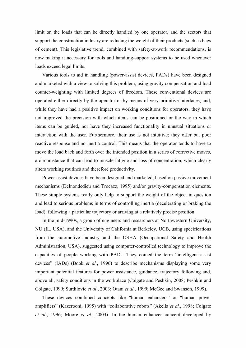
Figure 9 shows what the PAD looks like. The location of the drivers and the control
computer are shown. Table 2 summarizes the main mechanical and electrical features
of the PAD.
Input axis
Output axes
Input axis Fixed pinions
Satellite pinion
Fig. 7. Differential system of the wrist

Fig. 8. Wrist joint torques as a function of the wrist pitch and roll angles
-100-50
050
100
-100
0
100-200
0
200
400
Pitch (degrees)Roll (degrees)
Tor
que
in jo
int
1 (N
m)
-100-50
050
100
-100
0
100-200
0
200
400
Pitch (degrees)Roll (degrees)
Tor
que
in jo
int
2 (N
m)

5. Conclusions
The work presented herein is part of a long-term research project devoted to
configuring a manipulator for helping operators handle heavy loads, thus preventing
musculoskeletal disorders. This article focuses on the design of the manipulator
structure, and it affords a preview of some general features.
The design focuses on reducing the required joint torques in order to handle the
heaviest possible payloads. Thus, the manipulator is based on electric actuators
characterized by their low torque/weight ratio.
The main result is a new manipulator arm structure that consists of a mixture of a
SCARA manipulator and a parallelogram structure that allows the operator to move
inside its workspace. The wrist structure is based on a differential system that allows
two motors to provide the required torque in a collaborative way. A detailed analysis of
the wrist mechanism is provided, showing how joint torques are accurately determined.
Some additional features of the PAD, addressing the issues of robot guidance and
control, are given in Section 4.
Work is ongoing to provide the PAD with the sensors and interfaces required to
configure an intelligent power-assist device (IPAD).
ACKNOWLEDGEMENT
This work is supported by the Spanish Ministry of Science and Innovation through
Grant DPI2007-65728.
Figure 9. PAD prototype
Computer
Column
Drivers
1st link
2nd link
Extensor
3rd link
Wrist motor 4
Wrist motors 5 and 6

REFERENCES
Akella, M, Peshkin, M., Colgate E. and Wannasuphoprasit W., (1998), “Cobots – a
novel Material Handling Technology”, Proceedings of the ASME Winter Annual
Meeting.
Book W., Charles H., Davis H., and Gomes M., (1996), “The Concept and
Implementation of a passive Trajectory Enhancing Robot”, Proceedings of ASME
Dynamic Systems Control Division, DSC-Vol. 58, pp.633-638.
Colgate E., Wannasuphoprasit W, and Peshkin, M., (1996), “Cobots Robots for
Collaboration with Human Operator”, Proceedings of the ASME Dynamic Systems
and Control Division, DSC-Vol. 58, pp. 433-440.
Colgate, J. E. and Peshkin, M. A, (2008), “Intelligent Assist Devices: Revolutionary
Technology for Material Handling”, Available in:
http://www.stanleyassembly.com/documents/en/Cobotics%20IAD%20White%20Pa
per.pdf
Dalmec Industrial Manipulators, (2009), Available in: http://www.dalmec.com/es/
Delnondedieu, Y. and Trocazz, J., (1995), “PADyC a passive arm with dynamic
constraint: a prototype with two DOF”, IEEE Conferenc on Medical Robotics and
Computed Assisted Surgery, pp 173-180.
Gonzalez de Santos, P, Estremera, J. Garcia, E. and Armada, M, (2003), “Manipulators
help out with plaster panels in construction”, Industrial Robot, Vol. 30, No. 6, pp.
508-514.
Kazerooni H., (1995), “The Human Power Amplifier Technology at the University of
California, Berkeley”, DSC Vol. 57-2, IMECE Proceedings of the ASME Dynamic
Systems and Control Division, ASME.
Leite, A.C., Lizarralde, F. and Hsu, L., (2006), “Hybrid Vision-Force Robot Control for
Tasks on Unknown Smooth Surfaces”, Proceedings of the IEEE International
Conference on Robotics and Automation, Orlando, Fl.
McGee, D. and Swanson, P., (1999), “Method of controlling an intelligent assist
device”, United States Patent 6204620, Available in:
http://www.freepatentsonline.com/6204620.html.
Moore, C. A., Peshkin, M. A. and Colgate J. E., (2003), “Cobot Implementation of
Virtual Paths and 3-D Virtual Surfaces”, IEEE Transactions on Robotics and
Automation, Vol. 19, No. 2, pp. 347-350, April.

OSHA, (2009). Available in: (http://osha.europa.eu/OSHA)
Otani, E. M., Bartlett, D. S., Akeel, H. A., Mcgee, D.H., Najdovski, L. Hobson, J. C.
Mcclosky, S. H., Bauer V. R. and Frease, R., (1999), United States Patent 6612449,
“Intelligent power assisted manual manipulator” Available in:
http://www.freepatentsonline.com /6612449.html.
Peshkin, M. A., Colgate, J. E., Wannasuphoprasit, W., Moore, C. A., Gillespie, R. B.,
and Akella, P., (2001), “Cobot architecture”. IEEE Transactions on Robotics and
Automation, Vol.17, No. 4, pp. 377-390.
Peshkin, M. A. and Colgate, J. E., (1999), “Cobots”, Industrial Robot, Vol. 26, No. 5,
pp. 335-341.
Surdilovic, D., Bernahardt and R., Zhang, L., (2003), “New intelligent power-assist
systems based on differential transmission”, Robotica, Vol. 21, pp: 295-30.