A New Approach in Mobile Robot Fault Tolerant Control ...
12
A New Approach in Mobile Robot Fault Tolerant Control. Minimizing Costs and Extending Functionality. CRISTIAN AXENIE Dunarea de Jos University Department of Automation and Industrial Informatics Stiintei Street, Galati Romania [email protected],http://robotics.viviti.com Abstract: Today’s trends in control engineering and robotics are blending gradually into a slightly challenging area, the development of fault tolerant real-time applications. Hence, applications should timely deliver synchro- nized data-sets, minimize latency in their response and meet their performance specifications in the presence of disturbances and faults. The fault tolerant behavior in mobile robots refers to the possibility to autonomously de- tect and identify faults as well as the capability to continue operating after a fault occurred. This paper introduces a real-time distributed control application with fault tolerance capabilities for differential wheeled mobile robots. ARTEMIC combines the power and flexibility of real-time open-source software, the robustness of nonlinear con- trol schemes, the efficiency of Kalman filtering and the extensibility of high-level programming languages for hardware interfacing. Specific design, development and implementation details will be provided in this paper. Key–Words: Mobile Robotics, Fault Tolerant Control, Sliding Mode Control, Extended Kalman Filter, Real Time Linux, Distributed Control, Grafcet March 4, 2010 1 Introduction By accepting the challenge to ensure fault tolerant real-time control of a self designed and built wheeled differential mobile robot the author has been able to develop a hierarchical software application that min- imizes costs and supports extensibility. Analytical software redundancy is implemented rather than hard- ware redundancy for fault detection and identification for the minimal robot structure. Following a brief ap- plication architecture overview is given so that one can get a proper image on the implementation specific. The main application is designed on a distributed, client-server pattern, based on a TCP/IP wireless com- munication. Next, the main layers of the server appli- cation are listed maintaining a direct connection to the mobile robots features. The applications base level is built over the interface with the actuators (H-bridge MOSFET driver and 2 DC motors) and sensors (en- coders and bumpers) found in the robots structure. The next level is the control and fault tolerance level, to the extent that the control algorithm is implemented here and loops concurrently with the monitoring and fault tolerance task to ensure the robot’s autonomy and performance in trajectory tracking operation. The Grafcet was chosen to be the tool to support various control algorithm implementations and ensures proper serial / parallel execution of the control and monitor- ing tasks. The fault tolerant module is based on an set of Extended Kalman Filters used to estimate the current robot position and is using a residual compu- tation and a statistical analysis to determine if a fault occurred in the system and to discriminate between the faults. The fault tolerant module is comprised of a fault detection sub-module, a fault identification sub-module and also a control reconfiguration sub- module. The third level is a responsible with the com- munication task, to the extent that it implements a data server and a control server to ensure reliable data and command flows over a wireless network to the other nodes in the distributed system. The client application was designed to meet some specific requirements. The first type of client is responsible of interacting with the robot operation, basic start, stop, pause actions of the robot, but also with monitoring the status of the robot by receiving specific packets with sensor data. Due to the need of interactivity when injecting the faults a software fault injection framework was developed at this level. It’s purpose is to inject a certain fault at a certain moment in time chosen by the client user. The second type of client is limited only to access data logs WSEAS TRANSACTIONS on SYSTEMS and CONTROL Cristian Axenie ISSN: 1991-8763 205 Issue 4, Volume 5, April 2010
Transcript of A New Approach in Mobile Robot Fault Tolerant Control ...
A New Approach in Mobile Robot Fault Tolerant Control.Minimizing Costs and Extending Functionality.
CRISTIAN AXENIEDunarea de Jos University
Department of Automation and Industrial InformaticsStiintei Street, Galati
[email protected],http://robotics.viviti.com
Abstract: Today’s trends in control engineering and robotics are blending gradually into a slightly challengingarea, the development of fault tolerant real-time applications. Hence, applications should timely deliver synchro-nized data-sets, minimize latency in their response and meet their performance specifications in the presence ofdisturbances and faults. The fault tolerant behavior in mobile robots refers to the possibility to autonomously de-tect and identify faults as well as the capability to continue operating after a fault occurred. This paper introducesa real-time distributed control application with fault tolerance capabilities for differential wheeled mobile robots.ARTEMIC combines the power and flexibility of real-time open-source software, the robustness of nonlinear con-trol schemes, the efficiency of Kalman filtering and the extensibility of high-level programming languages forhardware interfacing. Specific design, development and implementation details will be provided in this paper.
Key–Words: Mobile Robotics, Fault Tolerant Control, Sliding Mode Control, Extended Kalman Filter, Real TimeLinux, Distributed Control, Grafcet
March 4, 2010
1 Introduction
By accepting the challenge to ensure fault tolerantreal-time control of a self designed and built wheeleddifferential mobile robot the author has been able todevelop a hierarchical software application that min-imizes costs and supports extensibility. Analyticalsoftware redundancy is implemented rather than hard-ware redundancy for fault detection and identificationfor the minimal robot structure. Following a brief ap-plication architecture overview is given so that onecan get a proper image on the implementation specific.The main application is designed on a distributed,client-server pattern, based on a TCP/IP wireless com-munication. Next, the main layers of the server appli-cation are listed maintaining a direct connection to themobile robots features. The applications base level isbuilt over the interface with the actuators (H-bridgeMOSFET driver and 2 DC motors) and sensors (en-coders and bumpers) found in the robots structure.The next level is the control and fault tolerance level,to the extent that the control algorithm is implementedhere and loops concurrently with the monitoring andfault tolerance task to ensure the robot’s autonomyand performance in trajectory tracking operation. TheGrafcet was chosen to be the tool to support various
control algorithm implementations and ensures properserial / parallel execution of the control and monitor-ing tasks. The fault tolerant module is based on anset of Extended Kalman Filters used to estimate thecurrent robot position and is using a residual compu-tation and a statistical analysis to determine if a faultoccurred in the system and to discriminate betweenthe faults. The fault tolerant module is comprisedof a fault detection sub-module, a fault identificationsub-module and also a control reconfiguration sub-module. The third level is a responsible with the com-munication task, to the extent that it implements a dataserver and a control server to ensure reliable data andcommand flows over a wireless network to the othernodes in the distributed system. The client applicationwas designed to meet some specific requirements. Thefirst type of client is responsible of interacting with therobot operation, basic start, stop, pause actions of therobot, but also with monitoring the status of the robotby receiving specific packets with sensor data. Dueto the need of interactivity when injecting the faults asoftware fault injection framework was developed atthis level. It’s purpose is to inject a certain fault at acertain moment in time chosen by the client user. Thesecond type of client is limited only to access data logs
WSEAS TRANSACTIONS on SYSTEMS and CONTROL Cristian Axenie
ISSN: 1991-8763 205 Issue 4, Volume 5, April 2010
from the robot, currently not used. ARTEMIC or Au-tonomous Real Time Embedded Mobile robot Intelli-gent Controller was developed as the diploma thesisproject by the author.
2 Server-side application description
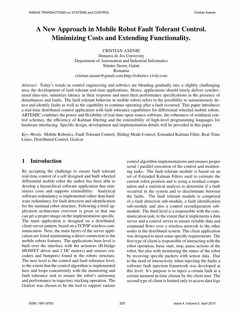
Next an extended description of the server-side appli-cation running on the robot embedded computer isgiven. All architectural and functional aspects willbe presented, with focus on both software develop-ment elements and implemented control engineeringconcepts. The server-side application is a real-timeLinux C/C++ application. The real-time capabilitieswere obtained at the OS level by modifying the stan-dard Linux kernel with the RTAI (Real Time Appli-cation Interface) patch based on ADEOS (AdaptiveDomain Environment for Operating Systems)to theextent that the enhanced micro-kernel can ensure aproper preemption level and I/O latency minimiza-tion. The hardware interface with the sensors andactuators is ensured by a data acquisition card (NI-PCI6024E) managed by a powerful kernel-space real-time driver and a rich API in user-space, both partof the COMEDI (Linux COntrol and MEasurementDevice Interface). To properly manage the executionof the two main tasks, namely the control task andthe monitoring task the application is organised onan abstract Grafcet (Graphe Fonctionnel de Controldes Etapes et Transitions) which supports the higherlevel parallelism in the execution of the two tasks.The control task is comprised of two inner speed con-trol PID loops (running at 50ms) for the 2 DC mo-tors and a main robot position control loop based ona sliding mode controller(running at 200ms). Con-currently, the monitoring and diagnosis task receivessensor data which is then processed by a set of 5 Ex-tended Kalman Filters every 50 ms. By examining thereal and predicted data the application can decide ifa fault occurred and what kind of fault based only onsensor information using a simple thresholding mech-anism and a statistical test on the residuals. Next anarchitectural overview of the whole application is de-picted in figure 1.
Figure 1: Main application architecture.
2.1 Base level description
The base level is the main support for the control andmonitoring tasks to the extent that the sensors and ac-tuators are interfacing with the software by the real-time data I/O features given by the Linux+RTAI andCOMEDI tools. The developed application is basedon a typical object-oriented pattern abstracting all thehardware through generic and flexible classes that areencapsuling specific functionality. As mentioned ear-lier the main application was developed on top of anenhanced Linux OS to extend its real-time features byusing a dual-kernel approach introduced by RTAI.[5]Currently the root OS is a Red Hat 9 Linux distro us-ing a 2.4.24 kernel and RTAI 3.0. This dual kernelapproach implies that the real-time micro-kernel is in-serted between the hardware and the root Linux OS,it has it’s own task scheduler and it doesn’t dependon the Linux critical sections. The micro-kernel haspriority to catch I/O interrupts for it’s real-time rou-tines before Linux (that has a secondary priority leveland is receiving only virtual interrupts). To minimizelatency the micro-kernel ensures low task-switchingperiods and some specific inter process communica-tion mechanisms with Linux. Due to it’s main advan-tages described earlier RTAI was chosen to supportthe development of the application. On top of the new
WSEAS TRANSACTIONS on SYSTEMS and CONTROL Cristian Axenie
ISSN: 1991-8763 206 Issue 4, Volume 5, April 2010

OS a real-time I/O driver was added. The COMEDIDAQ card driver fits well on top of RTAI and enhancesdata transfers and I/O with low latencies. COMEDI iscomprised of a kernel-space driver and an user spaceAPI named Comedilib built on a hierarchical patternto the extent that each DAQ card is composed of de-vices, subdevices and channels. Next the presentationshall focus on the base level of the server-side appli-cation running on the embedded robot computer. Thespecific I/O functions are presented in the applicationcontext. The server-side application is described infigure2.
Figure 2: Server-side application architecture.
To properly understand how the robot control ap-plication works, a typical operation context is de-scribed, emphasizing class communication during ex-ecution. Each sampling period the application readsthe data through the DAQ card from the encoders andcomputes, according to the read values, a control sig-nal for the 2 DC motors. The specific functions toobtain a value from a sensor or to set a value to an ac-tuator are comprised in the Counter, Sensor and Ac-tuator classes. Each of these classes calls specificuser-space COMEDI functions and accesses specificsensors through derived classes like the AnalogSen-sor that monitors the current variation in the motorswhen the load changes. For the bumpers a DigitalSen-sor class object was created and a Counter object isused to access the values (number of pulses) receivedon the DAQ card’s 12bit counters from the two en-coders, used in the odometry computation. Next theouter sliding mode loop computes the control signalfor the robot to achieve the next point in the trajectoryin a timely manner and then the computed control sig-nal is transformed in speed set-points for the inner PIDloops. The PID loops are computing a speed controlsignal for the motors which is then transformed us-ing a look-up table in the corresponding input voltagefor the H-bridge driver which outputs PWM signals
to each of the two motors. The monitoring and di-agnosis task that runs concurrently is fed with sensordata, in fact the odometry computations and each sam-pling period the 5 EKF are testing if a fault occurredand if occurred, what kind of fault is it. The fault tol-erant control module is then issuing specific warningmessages to the client application regarding the cur-rent status of the robot operation. Next an in depthdescription of the two tasks running on the embeddedrobot controller is given.
2.2 Control algorithm level description
As mentioned earlier the robot is operating in trajec-tory tracking mode so its main objective is to followa certain trajectory under time constraints. The con-trol algorithm goal is to minimize the position errors,namely the longitudinal error, the lateral error and theheading error. To ensure proper error convergence inthe presence of disturbances and modelling uncertain-ties a sliding mode controller was chosen. A slidingmode controller based on the kinematic model of therobot was used. By using a sliding mode controller atrade-off between tracking performance and paramet-ric uncertainty was made, to the extent that it providesa good solution in maintaining the stability and con-sistent performance in the face of modelling impreci-sion and disturbances.[6,9] Next the complete robotcontrol system is presented in figure3.
Figure 3: Control system architecture.
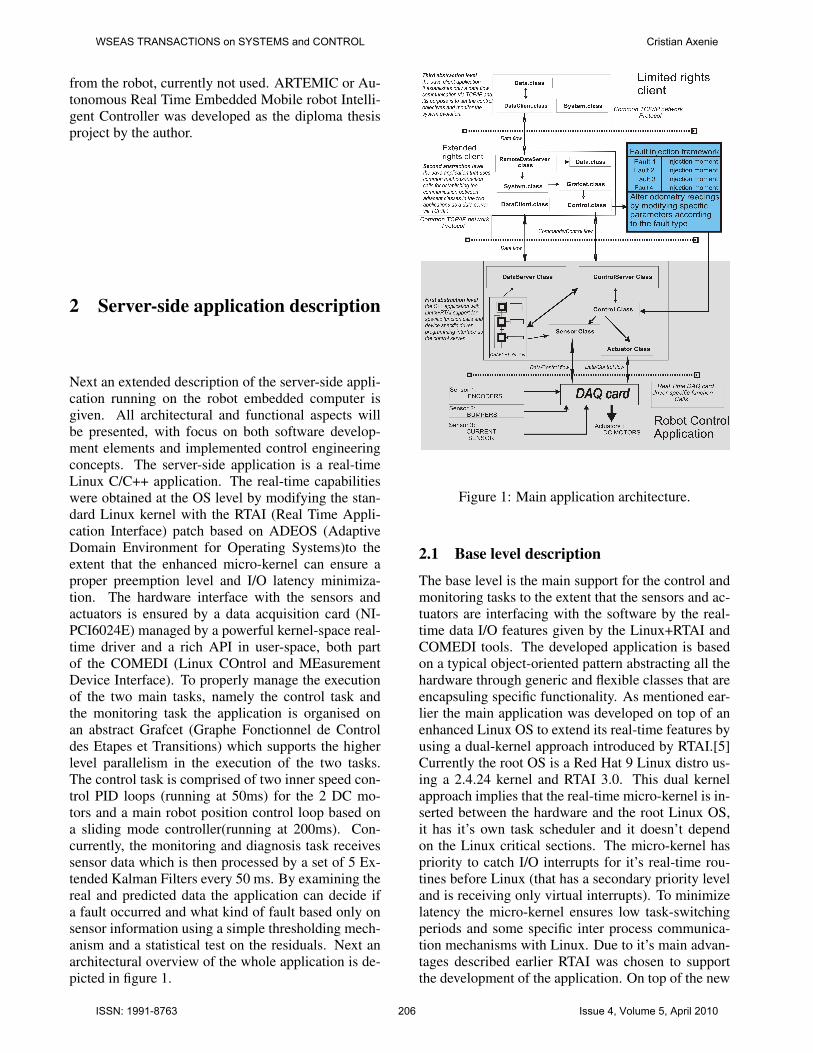
The robot should track the reference parametrizedcurve with time constraints and so real-time controlsignal computation is critical. The main idea behindthe trajectory tracking operation mode considers a vir-tual robot that tracks the reference trajectory with noerror and ”pulls” the real robot after it to the extentthat the controller reacts to minimize the errors.[3]The generic trajectory tracking problem is depicted infigure4.
WSEAS TRANSACTIONS on SYSTEMS and CONTROL Cristian Axenie
ISSN: 1991-8763 207 Issue 4, Volume 5, April 2010
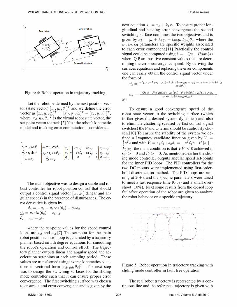
Figure 4: Robot operation in trajectory tracking.
Let the robot be defined by the next position vec-tor (state vector) [xr, yr, θr]T and we define the errorvector as [xe, ye, θe]T = [xd, yd, θd]T − [xr, yr, θr]T ,where [xd, yd, θd]T is the virtual robot state vector, theset-point vector to track.[2] Next the robot’s kinematicmodel and tracking error computation is considered.
The main objective was to design a stable and ro-bust controller for robot position control that shouldoutput a control signal vector [vc, ωc] (linear and an-gular speeds) in the presence of disturbances. The er-ror derivative is given by
xe = −vd + vrcos(θe) + yeωdye = vrsin(θe)− xeωdθe = ωr − ωd
where the set-point values for the speed controlloops are vd and ωd.[7] The set-point for the mainrobot position control loop is generated by a trajectoryplanner based on 5th degree equations for smoothingthe robot’s operation and control effort. The trajec-tory planner outputs linear and angular speed and ac-celeration set-points at each sampling period. Thesevalues are transformed using inverse kinematics equa-tions in vectorial form [xd, yd, θd]T . The next stepwas to design the switching surfaces for the slidingmode controller such that it can ensure proper errorconvergence. The first switching surface was chosento ensure lateral error convergence and is given by the
next equation s1 = xe + k1xe. To ensure proper lon-gitudinal and heading error convergence the secondswitching surface combines the two objectives and isgiven by s2 = ye + k2ye + k0sgn(ye)θe, where thek1, k2, k3 parameters are specific weights associatedto each error component.[11] Practically the controlsignal could be computed using s = −Qs−Psgn(s)where Q,P are positive constant values that are deter-mining the error convergence speed. By deriving thesurfaces equations and replacing the error componentsone can easily obtain the control signal vector underthe form of
vc = −Q1s1−P1sgn(s1)−k1 (xe)−ωdye−ωdye+vr θesin(θe)+vd
cos(θe)
ωc = −Q2s2−P2sgn(s2)−k2 (ye)−vrsin(θe)+ ˙ωdxe+ωdxe
vrcos(θe)+k0sgn(ye)+
ωd
To ensure a good convergence speed of therobot state vector to the switching surface (whichin fact gives the desired system dynamics) and alsoto eliminate chattering (caused by fast control signalswitches) the P and Q terms should be cautiously cho-sen.[10] To ensure the stability of the system we de-fined a Lyapunov candidate function given by V =12sT s and with V = s1s2+s2s1 = −sTQs−P1|s1|−
P2|s2| the main condition is that V V < 0 achieved ifQi >= 0 and Pi >= 0. As mentioned earlier the slid-ing mode controller outputs angular speed set-pointsfor the inner PID loops. The PID controllers for thetwo DC motors were implemented using first-order-hold discretization method. The PID loops are run-ning at 20Hz and the specific parameters were tunedto meet a fast response time (0.5s) and a small over-shoot (10%). Next some results from the closed loopfault-free operation of the robot are given to analyzethe robot behavior on a specific trajectory.
Figure 5: Robot operation in trajectory tracking withsliding mode controller in fault free operation.
The real robot trajectory is represented by a con-tinuous line and the reference trajectory is given with
WSEAS TRANSACTIONS on SYSTEMS and CONTROL Cristian Axenie
ISSN: 1991-8763 208 Issue 4, Volume 5, April 2010

crosses. The movement direction is indicated by ar-rows. As one can see the position error is kept inacceptable limits by the robust sliding mode con-troller and the robot can achieve it’s objective in time.Once more one can observe that good performance isachieved in using the sliding mode controller. To an-alyze the sliding mode controller operation next thelinear and angular velocities variations of the robot arepresented. Each graph contains the set-point evolutionand the real robot velocity.
Figure 6: Linear and angular velocities variation dur-ing robot operation.
Previously depicted, the set-points given by thetrajectory planner are marked in red and the real robotvelocities are marked in blue. Once more one canobserve that good performance is achieved in usingthe sliding mode controller. Another important as-pect regards the analysis of the error components inthe fault free operation, because it can be consideredas a proper validation for the controller. Next the threeerror components are depicted.
Figure 7: Robot longitudinal error (xe).
Figure 8: Robot lateral error ye.
Figure 9: Robot heading error θe.
One can see that the error convergence is prop-erly ensured by the controller. The longitudinal errorin the fault free operation is under 3cm, the lateral er-ror is under 6cm and the heading error in under 8 rads.
WSEAS TRANSACTIONS on SYSTEMS and CONTROL Cristian Axenie
ISSN: 1991-8763 209 Issue 4, Volume 5, April 2010

Experiments have shown that even for simpler trajec-tories (simple 2m line, 0.75m radius circle) the con-troller behaves well and despite the fact that the robotstructure had some hardware limitations (small en-coder resolution, 500PPR) the real-time control goalswere met even for slightly high sampling periods;allthe results are validated with the earlier error analy-sis. Following the next level of the application is pre-sented, namely the fault detection and identificationmodule and the support for fault tolerant control.
2.3 Monitoring and diagnosis level descrip-tion
Mobile robot fault tolerant control refers to the pos-sibility to autonomously detect by software if a faultoccurred in the robot’s structure or operation environ-ment so that the robot cannot satisfy its objectives.[1]Due to hardware limitations in injecting faults the ap-plication is also responsible to inject faults by soft-ware using a fault injection framework. By benefitingof a certain degree of robustness given by the slidingmode controller the application resides on a simplemechanism for fault detection, identification and sup-port for control reconfiguration based on the ExtendedKalman Filter (EKF). So, the application implementsa set of 5 EKF that form the fault detection and iden-tification module. It is known that the Kalman filteris basically a set of equations implementing an opti-mal estimator, by minimizing the estimate error co-variance when certain conditions are satisfied. It canbe used for both parametric or state estimation. Theextended Kalman filter, EKF, is used mostly when theprocess model or the measurement-process relationsare nonlinear, so it fits well in this application. Thisapproach using EKF is a multi-model based methodfor fault detection.[4] The current application consid-ers a fault benchmark comprised of faults manifestedby system’s parameter variation specifically mechan-ical faults that alter the robot behavior. Hence twofault classes were defined each containing two typesof faults. The first class of faults introduces the flattire fault for each of the robot wheels. At the imple-mentation level this fault exhibits by diminishing thewheel radius with a certain value. As a consequencethe whole kinematic model of the robot is modifiedand visible modifications in the robot’s behavior willbe present. The second class of faults introduces a pe-riodic variation of the wheel radius (a bump, causedhypothetically by an object attached to the wheel).Hence, for a small time period the variation will mani-fest itself and alter the robot operation. As mentionedearlier a fault injection framework was implementedand its main purpose is to alter the values from thesensors in odometry specific computations. Hence,
when no fault is injected the robot will behave nor-mally (as presented when the control level was de-scribed) but when a fault was injected the robot po-sition determining system (in fact the control systemfeedback, odometry) will feed altered data to the con-troller as if a physical fault occurred. Next a depic-tion of the fault detection and identification module isgiven.
Figure 10: Fault detection and identification module.
Each of the five EKF encapsules a kinematicmodel of the robot but with different parameters. Themain idea resides on the fact that for the same inputvector, z, with noise, each filter generates a predic-tion of the robot’s state vector. Each filter is associ-ated with a certain fault type. EKF0 is the nominalfilter corresponding to the fault free robot operation.EKF1 filter contains the same robot kinematic modelbut with modified parameters to emphasize the righttire flat fault, so the right wheel radius has a smallervalue. Hence, the prediction of EKF1 will be the robotstate vector if a right tire flat occurred. The EKF2filter is similar to EKF1 excepting it encapsules theleft tire flat fault specific model. In the same way theother two filters associated with the second fault class,EKF3 and EKF4, are predicting the robot’s state vec-tor in the presence of a second fault class fault. Be-sides the state estimate each EKF generates a mea-surement vector estimate during the prediction stage,which is used in the correction stage of the filter. Ba-sically the detection method is based on a nominalresidual computation and a simple thresholding teston the nominal residual which can output that a faultoccurred. It is the only one affected by the fault oc-currence so it will step out from some preset value in-tervals. When identifying the fault the application just
WSEAS TRANSACTIONS on SYSTEMS and CONTROL Cristian Axenie
ISSN: 1991-8763 210 Issue 4, Volume 5, April 2010

finds the smallest residual from the 5 ones, becausewhen a fault occurs the main measurement vector isaltered and it nears the predicted measurement vec-tor by the EKF encapsuling that fault behavior. Next,specific implementation details of the EKFs are pre-sented. Starting from the generic structure during theimplementation some simplifying hypothesis were is-sued and we know that Q is the process noise covari-ance matrix, R is the measurement covariance matrix,σx = σy = σθ = 0.1 are the standard deviationsfor the process noise, σmeas = 0.01 is the standarddeviation of the measurement noise.[8] To correctlydetect if a fault occurred some statistical tests on theresidual are required. The statistical parameters of theresidual (mean and variance) will be compared on-lineat each sampling period with the values obtained forthese parameters in fault-free operation. In fault-freeoperation the residual is a a white noise sequence with0 mean and ηk = Hk(x−k )P−k H
Tk (x−k ) + R variance.
Basically if a fault occurs in the system it will deter-mine a modification of the next residual based stan-dard sequence,
ηsk = (ηk = Hk(x−k )P−k HTk (x−k )+R)−1/2(yk−
hk(x−k )) = η−1/2k rk The goal is to determine the es-
timate of the real value of a sample given by ˆηs =1NΣηsj , where N is the number of samples. So, in thehypothesis H0 of no fault ˆηs has a gaussian distribu-tion with 0 mean and 1/N covariance. Over a certainacceptance threshold the H0 hypothesis is no longertrue and so a new hypothesis H1 is now true markinga fault occurrence. Next some experimental resultsare presented. First it is useful to analyze the residu-als generated by the nominal filter when a fault occurs,in fact these residuals are those predicted by the faultembedding filters, from the moment the fault occurs.For example if a right tire flat fault occurs at sample100 in the execution the residual evolution from 100thsample is the predicted residual by the EKF1.
Figure 11: Residual analysis for first fault class.
More, if a left wheel bump fault occurs at sample100 in the execution the residual evolution from 100thsample is the predicted residual by the EKF4.
Figure 12: Residual analysis for a second fault classfault.
From this separate residual analysis one can seethat each EKF is sensitive to a certain fault type andusing these properties the detection and identificationmodules were built. Assuming that a right tire flatfault was injected at moment t=10s and the new radiusof the wheel is 3cm smaller than the initial value thebehavior of the robot is altered as one can see in thenext figure.
Figure 13: Robot faulty operation vs. reference tra-jectory.
Next an extended position error analysis over thefault free and faulty operation is given (red marks faultfree operation and blue the faulty operation).
WSEAS TRANSACTIONS on SYSTEMS and CONTROL Cristian Axenie
ISSN: 1991-8763 211 Issue 4, Volume 5, April 2010

Figure 14: Longitudinal error comparison fault-free/faulty operation.
Figure 15: Lateral error comparison fault-free/faultyoperation.
Figure 16: Heading error comparison fault-free/faultyoperation.
As one can see there are major variations from thenominal behavior after a fault occurred in the system.
To validate the detection mechanism the latency, mea-sured as the time between the fault occurred (in factinjected by the injection framework) and the momentwhen it has been detected, is very important. Nextthe latency is marked by pausing the robot operationwhen a fault was detected.
Figure 17: Detection analysis.
It is important to mention that the thresholdingmechanism reacts if at least two components of theresidual vector are bigger than the preset values. So,the fault could be visible in all the residual compo-nents or not. As a typical operation context when afault is detected, it is then identified and the clientapplication is informed what kind of fault occurred.At the moment only one fault can be detected and
WSEAS TRANSACTIONS on SYSTEMS and CONTROL Cristian Axenie
ISSN: 1991-8763 212 Issue 4, Volume 5, April 2010

identified, no fault queue or priority system are im-plemented. Following a brief description of the clientapplication is given.
3 The client-side application descrip-tion
The two main components of the application arelinked through a wireless communication which sus-tains data and control flows between the distributedsystem nodes, namely the server, an embedded linuxC++ application and the client , a Java GUI applica-tion. The communication level is based on two servertype classes ControlServer and DataServer both basedon socket level communication and using specificdesigned functions like connect(), serve requests(),serve client(), send() and receive(). The client appli-cation is responsible with the external events that de-termine the robot operation. It implements a similarstructure with the embedded application and supportsthe fault injection framework to the extent that the useroperating the client can choose the moment, type andgain of the fault before starting the robot operation.Next a synthetic image of the client application archi-tecture is given.
Figure 18: Client-side Java application architecture.
Besides the interactive task of injecting faults theclient application is responsible to choose the Grafcetstructure that encapsules the execution rules for thecontrol algorithm and and the specific supported ac-tions (start/pause/stop) for the robot operation, also itoffers the possibility to choose between multiple tra-jectories and to visualize the robot’s current position.
Figure 19: Client-side Java application GUI.
The two possible Grafcet execution schemes se-rial/parallel assume a serial or parallel execution ofuser defined tasks for the robot. Currently the two im-plemented tasks, real-time control and monitoring anddiagnosis must run concurrently to ensure consistentand valid results in the fault tolerant control problem.Next are depicted the two possible generic definitionsfor the internal Grafcet scheme used in the applica-tion.
Figure 20: Serial Grafcet scheme.
WSEAS TRANSACTIONS on SYSTEMS and CONTROL Cristian Axenie
ISSN: 1991-8763 213 Issue 4, Volume 5, April 2010

By using the serial scheme the application willrun the two main tasks sequentially with respect forthe chosen sampling period.
Figure 21: Parallel Grafcet scheme.
The current implemented scheme is the parallelone to ensure proper task concurrently but it sets someconstraints in choosing the sampling time due to thefact that the two tasks are complex and complex oper-ations should be executed concurrently. Using a fullload of the embedded system latency measurementswere taken. So, by using a 50ms sampling period forthe inner control loop and the monitoring and diagno-sis tasks and a 200ms sampling period for the robotposition controller good average ms level latencieswere obtained. Some measured latencies for the stan-dard, Low-Latency, preemptible and preemptible withlock-breaking kernels while running different loads inbackground. All the experiments were performed us-ing the Latency Benchmark tool.[10]
Figure 22: Latency in the Standard Kernel.
Figure 23: Latency in the Low Latency Kernel.
Figure 24: Latency in the preemptible Kernel.
Figure 25: Latency in the Real-Time Kernel.
From the first figure, it is possible to see thatstandard Linux exhibits high latencies at the end of
WSEAS TRANSACTIONS on SYSTEMS and CONTROL Cristian Axenie
ISSN: 1991-8763 214 Issue 4, Volume 5, April 2010

the memory stress, during the I/O stress, when ac-cessing the /proc file system, and when switching thecaps/lock led. The large latency at the end of the mem-ory stress is due to the munmap() system call. Com-paring the figures it is possible to see that the low la-tency kernel solves all the problems except the /procfile system access and the caps/lock switch. On theother hand, the preemptible kernel eliminates the largelatency in the /proc fs access, but does not solve theproblem with the memory stress, and is not as effec-tive as the low latency kernel in reducing the latencyduring the I/O stress. Finally, the real-time kernelseems to provide good real-time performance, withgood performance during I/O stress. Following a shortsynthetic overview over the paper is given emphasiz-ing the main advantages and some future work ideas.
4 Conclusions and future work
ARTEMIC was designed as a flexible application ded-icated to mobile robotics fault tolerant control. Itsarchitecture is open and supports extensibility at a”plug-an-play” level because at the lowest level it sup-ports and offers a simple mechanism to add new hard-ware to the robot and provides a generic and com-patible interface with the hardware. At the upperlevel it supports extended connectivity. The currentfault tolerant control problem was solved by properlyconnecting specific application architectural elementswith control engineering concepts. By using open-source software the costs were minimized and perfor-mance was maximized. As future work a port of thedeveloped application from the current Intel Celeronbased embedded computer to a MPC8315ERDB Pow-erPC platform is started. The new platform uses anenhanced RTOS named Xenomai that is a super-setof RTAI and it provides better performance and it isdedicated to embedded architectures. Another direc-tion in the future work regards the possibility to com-bine multiple fault detection and identification meth-ods to gain the advantages of each composing methodand obtain a hybrid and efficient mechanism. Thisapproach shall be combined with an adaptive slidingmode controller to the extent that it can self-adjustit’s parameters based on optimal criteria to ensurefaster error convergence. Next figure introduces theARTEMIC power robot.
Figure 26: The ARTEMIC powered mobile robot.
References:
[1] Patton R., Frank P., Clark R. Fault Diagnosis inDynamic Systems:Theory and Applications PrenticeHall, New York, 1989.
[2] Bruno Siciliano, Lorenzo Sciavicco, Luigi Villani,Giuseppe Oriolo Robotics, Modelling, Planning andControl Springer, 2009
[3] Razvan Solea, Urbano Nunes Trajectory Planningand Sliding Mode Control for WMR Trajectory Track-ing and Path Following Rescpecting Human ComfortTravel CONTROLO Conference Portugal, 2006.
[4] Mayback P.S.,Cox I.J.,Wilfong G.T.(eds) The KalmanFilter:An Introduction to Concepts in AutonomousRobot Vehicles Springer-Verlag, 1990
[5] Burns A., Wellings A. Real-Time Systems and Pro-gramming Languages AddWesley, California, 1996.
[6] Utkin V.I. Sliding Modes in Optimization and ControlProblems Springer-Verlag, New York, 1992.
[7] I. Susnea, G. Vasiliu, A. Filipescu Real-time, embed-ded fuzzy control of the Pioneer3-DX robot for pathfollowing 12th WSEAS International Conference onSYSTEMS, Heraklion, Greece, July 22-24, 2008
[8] EVGENIA SUZDALEVA,UTIA AV CR Initial Con-ditions for Kalman Filtering: Prior Knowledge Speci-fication Proceedings of the 7th WSEAS InternationalConference on Systems Theory and Scientific Compu-tation, Athens, Greece, August 24-26, 2007
[9] YONG XU, WANSHENG TANG, ZHUZHI YUANControl Design for Uncertain Systems Based onIntegral-Type Sliding Surface Proceedings of the 6thWSEAS International Conference on Robotics, Con-trol and Manufacturing Technology, Hangzhou, China,April 16-18, 2006
[10] STERGIOS PAPADIMITRIOU, KONSTANTINOSTERZIDIS Comparative evaluation of the recentLinux and Solaris kernel architectures Proceedings ofthe 11th WSEAS International Conference on COM-PUTERS, Agios Nikolaos, Crete Island, Greece, July26-28, 2007
WSEAS TRANSACTIONS on SYSTEMS and CONTROL Cristian Axenie
ISSN: 1991-8763 215 Issue 4, Volume 5, April 2010
[11] GAZENFER RUSTAMOV, MANAFADDIN NA-MAZOV, REFIK SAMET Sliding Modes in Finite-Time Control Systems with Variable Structure Pro-ceedings of the 9th WSEAS International Conferenceon Automatic Control - Modeling and Simulation, Is-tanbul, Turkey, May 27-29, 2007
WSEAS TRANSACTIONS on SYSTEMS and CONTROL Cristian Axenie
ISSN: 1991-8763 216 Issue 4, Volume 5, April 2010