A new approach for assessment of the performance...
17
A new approach for assessment of the performance efficiency of DCMD when desalting feeds of high salinity Omar A. Bamaga, Mohammad Albeirutty, Akram M. Nahri Center of Excellence in Desalination Technology King Abdulaziz University, Jeddah, Saudi Arabia
Transcript of A new approach for assessment of the performance...
A new approach for assessment of the performance efficiency of DCMD when
desalting feeds of high salinity
Omar A. Bamaga, Mohammad Albeirutty, Akram M. Nahri Center of Excellence in Desalination Technology King Abdulaziz University, Jeddah, Saudi Arabia
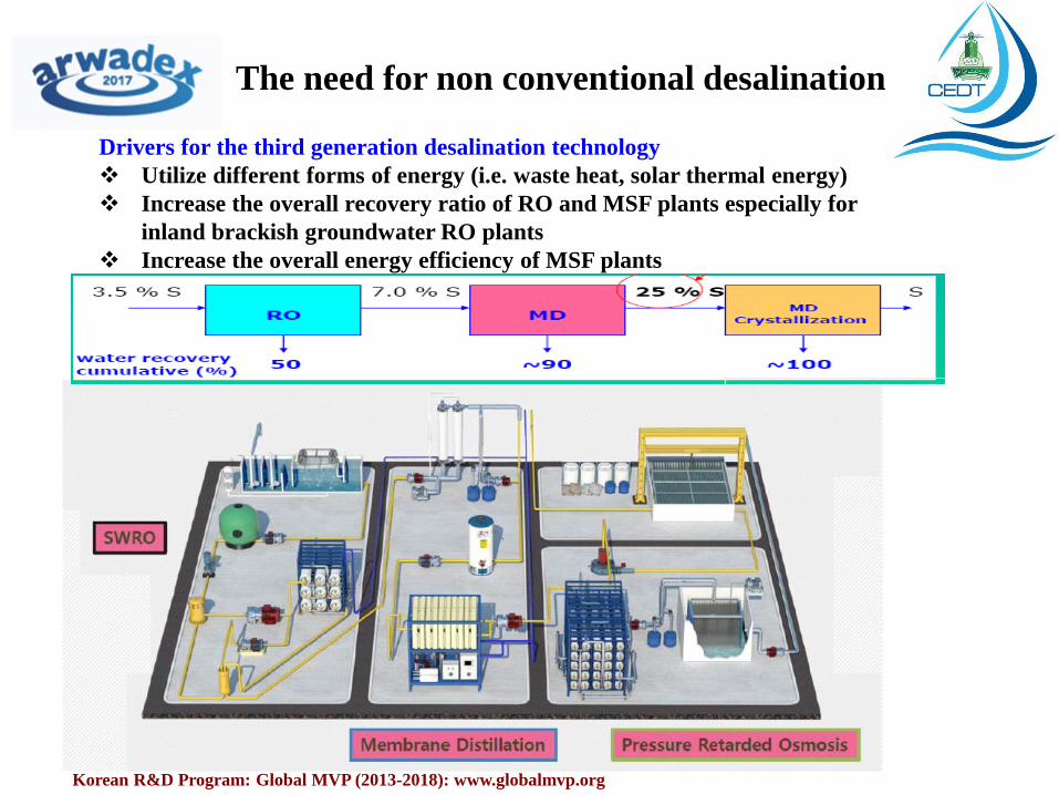
The need for non conventional desalination
Korean R&D Program: Global MVP (2013-2018): www.globalmvp.org
Drivers for the third generation desalination technology
Utilize different forms of energy (i.e. waste heat, solar thermal energy)
Increase the overall recovery ratio of RO and MSF plants especially for
inland brackish groundwater RO plants
Increase the overall energy efficiency of MSF plants

Membrane distillation (MD)
• MD is a thermal, phase change separation process
• Hydrophobic micro-porous membrane with pore size 0.1- 0.4 μm
• The driving force is the partial vapour pressure difference due to temperature difference across the hot and cold sides of the membrane
• Operates at low temperatures (50 - 70⁰C) (Suitable for RE, waste heat)
• Possibility to desalinate feeds with very high salinity
• Produces high quality water • Low hydrostatic pressure needed • Resistive against fouling and scaling • Modular and simple design • Low investment cost • No chemical pre-treatment of the feed
water.
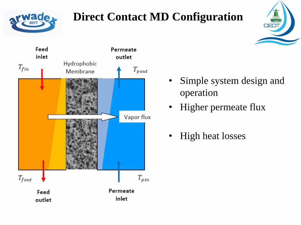
Direct Contact MD Configuration
• Simple system design and
operation
• Higher permeate flux
• High heat losses
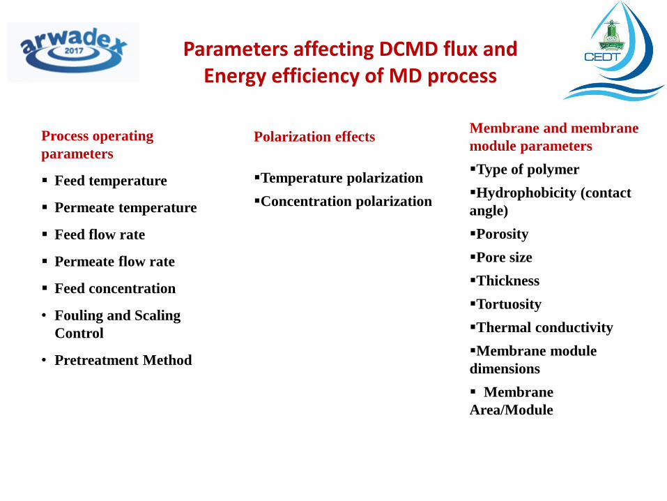
Parameters affecting DCMD flux and Energy efficiency of MD process
Process operating
parameters
Feed temperature
Permeate temperature
Feed flow rate
Permeate flow rate
Feed concentration
• Fouling and Scaling
Control
• Pretreatment Method
Polarization effects
Temperature polarization
Concentration polarization
Membrane and membrane
module parameters
Type of polymer
Hydrophobicity (contact
angle)
Porosity
Pore size
Thickness
Tortuosity
Thermal conductivity
Membrane module
dimensions
Membrane
Area/Module
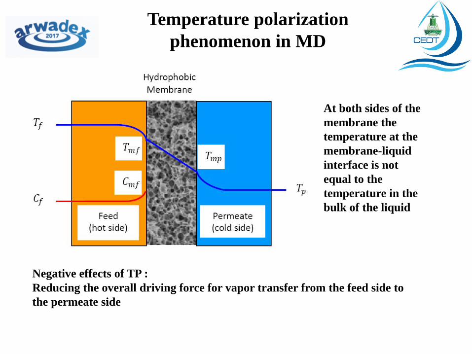
Temperature polarization
phenomenon in MD
At both sides of the
membrane the
temperature at the
membrane-liquid
interface is not
equal to the
temperature in the
bulk of the liquid
Negative effects of TP :
Reducing the overall driving force for vapor transfer from the feed side to
the permeate side

Temperature polarization
coefficient (TPC)
TPC is defined as the ratio of the trans-membrane temperature gradient to the difference between the temperatures of the feed and permeate bulk streams
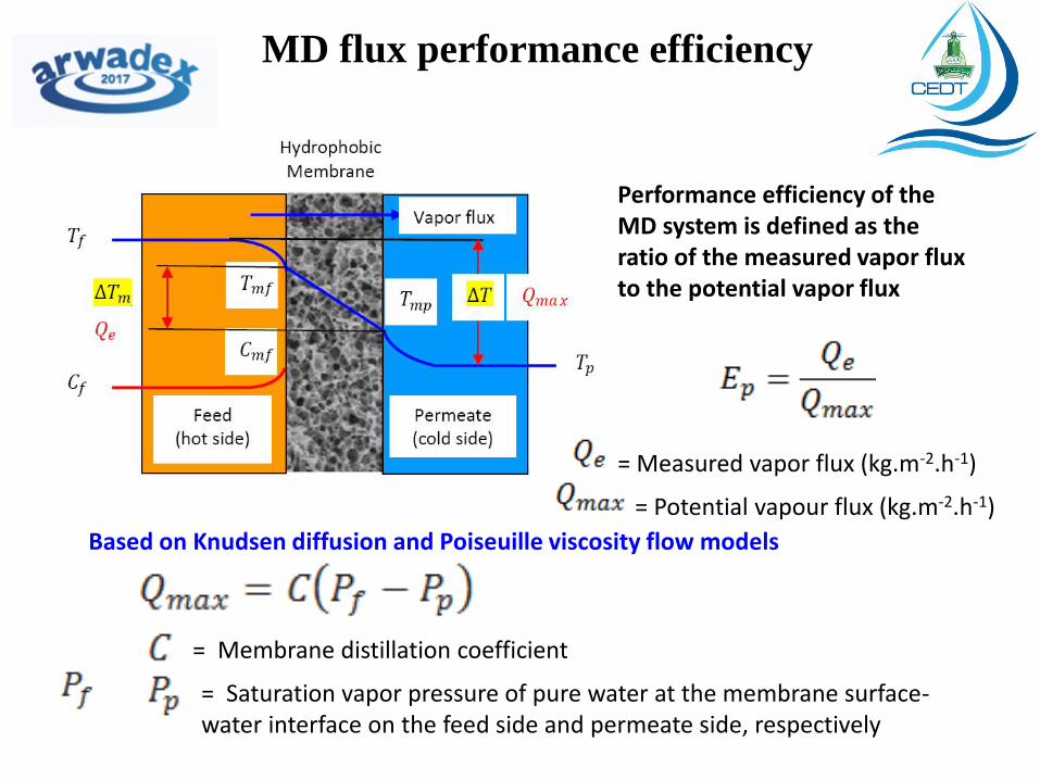
MD flux performance efficiency
Performance efficiency of the MD system is defined as the ratio of the measured vapor flux to the potential vapor flux
= Measured vapor flux (kg.m-2.h-1)
= Potential vapour flux (kg.m-2.h-1)
= Membrane distillation coefficient
= Saturation vapor pressure of pure water at the membrane surface-water interface on the feed side and permeate side, respectively
Based on Knudsen diffusion and Poiseuille viscosity flow models
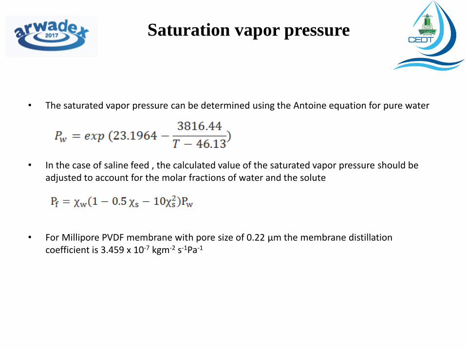
Saturation vapor pressure
• The saturated vapor pressure can be determined using the Antoine equation for pure water
• In the case of saline feed , the calculated value of the saturated vapor pressure should be adjusted to account for the molar fractions of water and the solute
• For Millipore PVDF membrane with pore size of 0.22 μm the membrane distillation coefficient is 3.459 x 10⁻⁷ kgm-2 s-1Pa-1
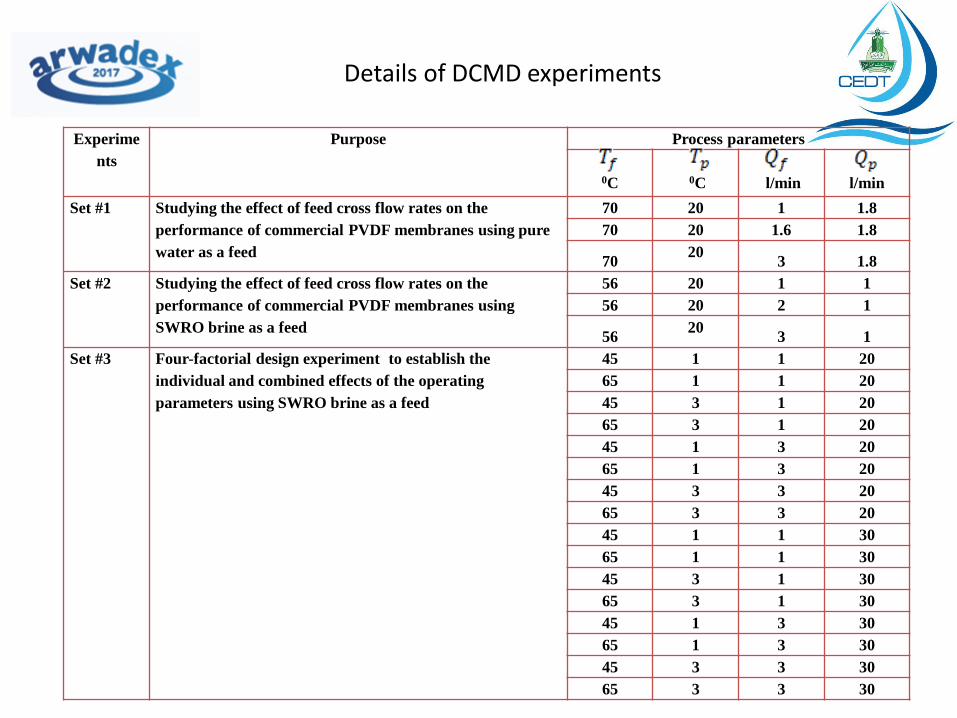
Details of DCMD experiments
Experime
nts
Purpose Process parameters
0C
0C
l/min
l/min
Set #1 Studying the effect of feed cross flow rates on the
performance of commercial PVDF membranes using pure
water as a feed
70 20 1 1.8
70 20 1.6 1.8
70 20
3 1.8
Set #2 Studying the effect of feed cross flow rates on the
performance of commercial PVDF membranes using
SWRO brine as a feed
56 20 1 1
56 20 2 1
56 20
3 1
Set #3 Four-factorial design experiment to establish the
individual and combined effects of the operating
parameters using SWRO brine as a feed
45 1 1 20
65 1 1 20
45 3 1 20
65 3 1 20
45 1 3 20
65 1 3 20
45 3 3 20
65 3 3 20
45 1 1 30
65 1 1 30
45 3 1 30
65 3 1 30
45 1 3 30
65 1 3 30
45 3 3 30
65 3 3 30
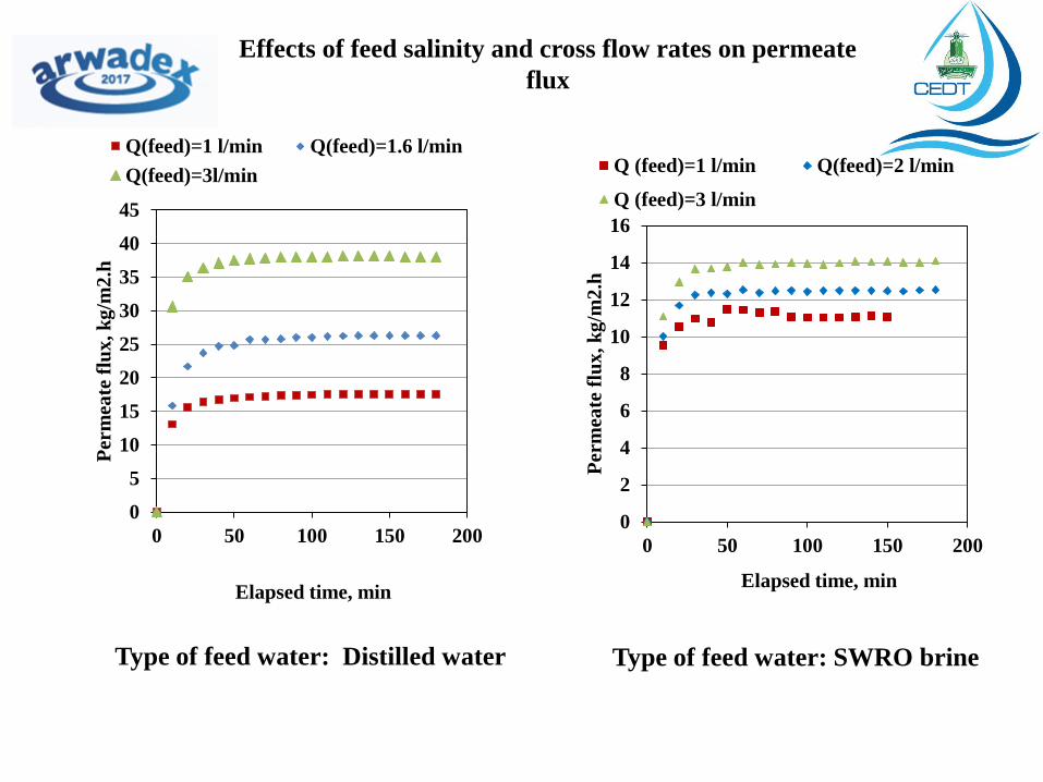
Effects of feed salinity and cross flow rates on permeate
flux
0
2
4
6
8
10
12
14
16
0 50 100 150 200
Per
mea
te f
lux
, k
g/m
2.h
Elapsed time, min
Q (feed)=1 l/min Q(feed)=2 l/min
Q (feed)=3 l/min
0
5
10
15
20
25
30
35
40
45
0 50 100 150 200
Per
mea
te f
lux
, k
g/m
2.h
Elapsed time, min
Q(feed)=1 l/min Q(feed)=1.6 l/min
Q(feed)=3l/min
Type of feed water: SWRO brine Type of feed water: Distilled water

Effect of operating parameters on DCMD permeate flux type of feed water: SWRO brine
0
5
10
15
20
25
0 1 2 3 4
J , k
gM
H
Qf, l/min
a) Qd=1 l/min, Td=20 C
Tf=45 C Tf=65 C
0
5
10
15
20
25
0 1 2 3 4
J , k
gM
H
Qf, l/min
b) Qd=3 l/min, Td=20 C
Tf=45 C Tf=65 C
0
5
10
15
20
25
0 1 2 3 4
J , k
gM
H
Qf, l/min
c) Qd=1 l/min, Td=30 C
Tf=45 C Tf=65 C
0
5
10
15
20
25
0 1 2 3 4
J , k
gM
H
Qf, l/min
d) Qd=3 l/min, Td=30 C
Tf=45 C Tf=65 C

Effect of operating parameters on MD flux performance efficiency
type of feed water: SWRO brine
0
0.1
0.2
0.3
0.4
0.5
0.6
0.7
0.8
0.9
1 3
Ep
Qf, l/min
a) Qd=1 l/min, Td=20 C
Tf=45 C Tf=65 C
0
0.1
0.2
0.3
0.4
0.5
0.6
0.7
0.8
1 3
Ep
Qf, l/min
b) Qd=3 l/min, Td=20 C
Tf=45 C Tf=65 C
0
0.1
0.2
0.3
0.4
0.5
0.6
0.7
1 3
E p
Qf, l/min
c) Qd=1 l/min, Td=30 C
Tf=45 C Tf=65 C
0
0.1
0.2
0.3
0.4
0.5
0.6
0.7
0.8
1 3
Ep
Qf, l/min
d) Qd=3 l/min, Td=30 C
Tf=45 C Tf=65 C
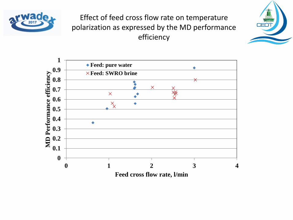
Effect of feed cross flow rate on temperature polarization as expressed by the MD performance
efficiency
0
0.1
0.2
0.3
0.4
0.5
0.6
0.7
0.8
0.9
1
0 1 2 3 4
MD
Per
form
an
ce e
ffic
ien
cy
Feed cross flow rate, l/min
Feed: pure water
Feed: SWRO brine
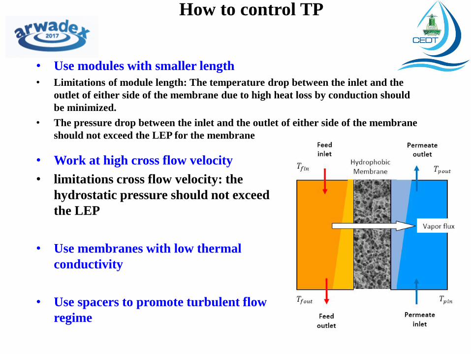
How to control TP
• Work at high cross flow velocity
• limitations cross flow velocity: the
hydrostatic pressure should not exceed
the LEP
• Use membranes with low thermal
conductivity
• Use spacers to promote turbulent flow
regime
• Use modules with smaller length
• Limitations of module length: The temperature drop between the inlet and the
outlet of either side of the membrane due to high heat loss by conduction should
be minimized.
• The pressure drop between the inlet and the outlet of either side of the membrane
should not exceed the LEP for the membrane
Current research efforts towards
optimization of MD Desalination
• Membrane development: engineered polymers + improved membrane preparation techniques
Aim: higher flux, lower fouling, lower wetting, improved rejection
• Module design and optimization: reduced temperature and concentration polarization and increased recovery ratio
• Use of cost-effective heat sources: Solar, boiler blowdown
• MD System design: lower energy use, higher performance, fouling and scaling control, wetting control

شكرا لكم
Thank You