A n ti -T h e f t P ac ka ge Se c ur it y Sy st e m
33
Anti-Theft Package Security System Team 36 - Nikhil Mehta, Irfan Suzali, Abishek Venkit ECE445 Project Proposal, Round 2 - Spring 2020 TA: Shuai Tang
Transcript of A n ti -T h e f t P ac ka ge Se c ur it y Sy st e m
Anti-Theft Package Security System Team 36 - Nikhil Mehta, Irfan Suzali, Abishek Venkit
ECE445 Project Proposal, Round 2 - Spring 2020 TA: Shuai Tang
Table of Contents
1 Introduction 3 1.1 Problem and Solution Overview 3 1.2 Visual Aid 5 1.3 High-Level Requirements 6
2 Design 7 2.1 Block Diagram and Flow Diagram 7 2.2 Physical Design 9 2.3 Power Supply 9
2.3.1 5V Wall Charger 9 2.3.2 Voltage Regulator 10
2.4 Perception Module 11 2.4.1 Raspberry Pi 11 2.4.2. Camera 12
2.5 Control Module 14 2.5.1 Microcontroller 14
2.6 Sensor Module 16 2.6.1 PIR Sensor 16 2.6.2 Ambient Light Sensor 16 2.6.3 Spotlight 16 2.6.4 Transistor Switch 16
2.7 WiFi Module 18 2.7.1 WiFi Transmission Module 18 2.7.2 Status LED 18
2.8 Alarm Module 19 2.8.1 DAC Filter 19 2.8.2 Output Speaker 19 2.8.3 Amplification Circuit 19
2.9 Schematics 21 2.10 Software 24
2.10.1 Computer Vision Package and Facial Recognition 24 2.10.2 Micrcontoller Dispatcher 24
2.11 Tolerance Analysis 24
3 Differences 26 3.1 Overview 26 3.2 Analysis 27
1

4 Cost and Schedule 28 4.1 Cost Analysis 28 4.2 Parts Acquisition 28 4.3 Schedule 29
5 Ethics and Safety 30
References 32
2
1 Introduction
1.1 Problem and Solution Overview Ordering packages online is extremely commonplace these days, with over 87 billion packages shipped worldwide in 2018 [1]. However, the added convenience can also have drawbacks. One of the risks of ordering a package online is theft. When packages are dropped off outside of an unprotected residence, it is easy for a thief to steal it without being caught. 36% of Americans have experienced package theft, and the average cost to replace a stolen package is $109. This is costly and inconvenient for the customer and supplier [2]. The package delivery industry is incredibly large and growing at a fast pace, which tells us that this problem is significant, and an affordable, reliable, and secure solution would help a lot of people protect their packages from theft. Our solution will implement computer vision to identify when packages are delivered and when they are picked up. This system will use a camera that is pointed at the location of delivery. The package will be delivered within a general area in the field of view of the camera. Once the package is delivered, the computer vision algorithm will detect its presence, and track it to ensure it stays in full view of the camera. The system will also notify the user via text using WiFi when it detects that a package has arrived. If anyone tries to move it, or if the package becomes obscured from the camera, an alarm will sound, the user is notified, and a short video recording will be taken of the offender. Furthermore, if anyone moves the actual camera system or tries to cover the camera, the alarm will sound as well. In order to disarm the alarm, the actual package recipient must show their face to the camera. This will disable the alarm from triggering for a short period, allowing the user to pick up their package. In order for this system to work at night, there will also be a motion sensored spotlight to illuminate the entryway. This implementation will use a computer vision object identification and facial recognition algorithm running on the Raspberry Pi. This model will be trained on various standard package shapes and sizes, to ensure that the system can recognize any package with the appropriate marking. The Raspberry Pi will only be used for the CV algorithm and storage system, and will transfer data to a separate microcontroller. This microcontroller will communicate with the Raspberry Pi, and the alarm, WiFi, and spotlight systems. The alarm system will require speaker/audio circuitry, which includes a digital-to-analog converter, amplifier, and speaker. The notification system will require a WiFi module and external cellular device to push text messages to the user. The spotlight system will require a PIR motion sensor, ambient light sensor, and lighting circuitry. The entire device will need a power supply and voltage regulation. In order to disarm the alarm and retrieve your package, the system will utilize a face recognition model to turn off the alarm system when it recognizes the user’s face. This will make the system seamless and easy to use, while still maintaining the security factors that are most important. Package security is a large industry with several existing solutions on the market. However, despite the growing adoption rate of home security systems, only 17% of homes have some type of security system installed [3]. There are several reasons that people don’t use home security systems. This includes the fact that they cost too much, they are difficult to use, and possibly infringe on privacy [4]. Related to the concern over high cost, many home security systems are fully featured, and serve many purposes beyond just package security. This is great if you want all of these extra features and can afford it, but there are few options if you only want a way to secure
3
your packages. Our system will also be easy to use, with a simple notification system and an easy way to disarm your system when you want to retrieve your package. The hardware will all be in one package, which will be easy to install and low cost. Another alternative package delivery solution aimed at reducing theft is choosing to ship your package to a package locker, like a PO box, or the more recent Amazon Locker [5]. This allows you to secure your package in a remote facility until you unlock it and pick it up. This solution is less than ideal as well, because it forces you to travel to a separate destination everytime you want to pick up a package. A more modern and techy solution is using smart locks to allow delivery inside your home, like the Amazon Key [6]. This solution eliminates the risk of package theft after delivery, but introduces a new concern of letting someone into your home to deliver your package. These smart lock systems are also expensive and require installation into your door. We have defined our target market for this product as anyone who orders packages regularly and wants an affordable way to monitor their package without investing in an expensive, fully-featured home security system. This is a large market, because such a small percentage of homes have home security systems. A major reason for this is the high price of home security systems, complicated usage, and fear of infringement on privacy. Considering our target market, the purchase conditions for a security system, and the many alternatives, our product excels when compared to the competition in a few key ways. Firstly, our system is focused on solving one specific common problem, allowing us to handle it in a complete and effective way. Other systems on the market have much broader goals, and thus become bloated and spread thin. Our system can focus more deeply on solving the problem of package theft. The next key strength comes as a byproduct of the first strength. By focusing on this single problem, we can make our system much more affordable than other competing products. Many consumers only want a system that will protect their packages from theft, and our product can provide that without any extra features or added cost. Finally, our product is easy to use and install, with simple features like face recognition to disarm and text notifications for package delivery and suspicious activity. Our product can seamlessly fit into our customers existing lifestyle and habits without a large learning curve or a complicated interface. These key benefits differentiate our product from the competition and provide value to our customers.
4
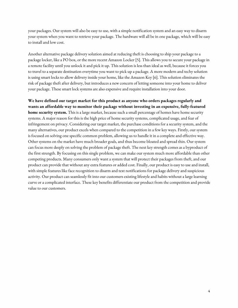
1.2 Visual Aid
Figure 1. Visual representation of how the system can be implemented at a typical home
5

1.3 High-Level Requirements In order for this system to be successful, it would need to reduce the risk of package theft from households, and if packages are stolen anyways, the system would need to provide a video record of the thief.
● The video recording system must capture thefts reliably (90% +/- 5% theft detection rate) and must disarm reliably using facial recognition (80% +/- 5% true positive facial recognition rate, 90 % +/- 5% true negative rate)
● The notification system must notify the user reliably (90% +/- 5% transmission reliability given an outgoing message)
● The sensor and lighting system must illuminate the scene in the dark reliably, using the PIR and ambient light sensors (90% +/- 5% accurate in identifying and responding to darkness below a given threshold when movement is detected)
6
2 Design
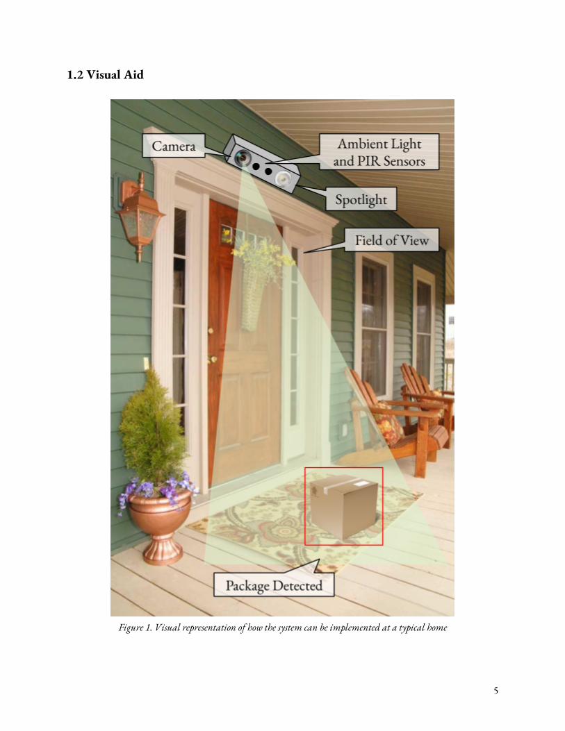
2.1 Block Diagram and Flow Diagram Our block diagram displays the distinct different modules in our design. The perception module is composed of the Raspberry Pi and the Raspberry Pi Camera, and will be connected to the control and power supply modules. The control module contains a PIC32 microcontroller. The motion sensor module will contain a PIR motion sensor, ambient light sensor, and a spotlight, and will interface with the control module to send and receive data. The alarm module will contain a DAC to convert a PWM signal to analog, and a medium sized speaker which will output the alarm signal. The WiFi module will contain a dedicated WiFi chip that will interface with the PIC32 over UART, and a LED status light to indicate transmission. Finally, the power supply module will allow us to convert outlet power (120V) into 5V and 3.3V for usage by the Raspberry Pi, PIC32, LED, speaker, and other components.
Figure 2. Block Diagram
7
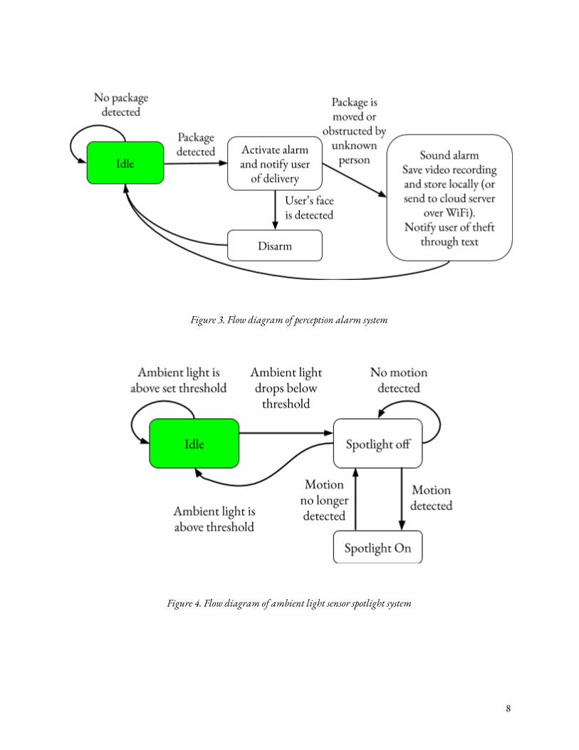
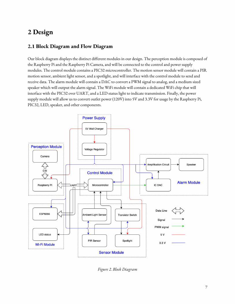
Figure 3. Flow diagram of perception alarm system
Figure 4. Flow diagram of ambient light sensor spotlight system
8
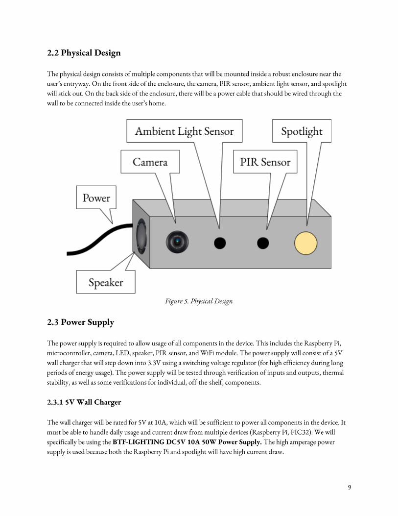
2.2 Physical Design The physical design consists of multiple components that will be mounted inside a robust enclosure near the user’s entryway. On the front side of the enclosure, the camera, PIR sensor, ambient light sensor, and spotlight will stick out. On the back side of the enclosure, there will be a power cable that should be wired through the wall to be connected inside the user’s home.
Figure 5. Physical Design
2.3 Power Supply The power supply is required to allow usage of all components in the device. This includes the Raspberry Pi, microcontroller, camera, LED, speaker, PIR sensor, and WiFi module. The power supply will consist of a 5V wall charger that will step down into 3.3V using a switching voltage regulator (for high efficiency during long periods of energy usage). The power supply will be tested through verification of inputs and outputs, thermal stability, as well as some verifications for individual, off-the-shelf, components. 2.3.1 5V Wall Charger The wall charger will be rated for 5V at 10A, which will be sufficient to power all components in the device. It must be able to handle daily usage and current draw from multiple devices (Raspberry Pi, PIC32). We will specifically be using the BTF-LIGHTING DC5V 10A 50W Power Supply. The high amperage power supply is used because both the Raspberry Pi and spotlight will have high current draw.
9
Off the shelf, this device is rated to output 5V at 10A. We will verify this output, and ensure device safety. 2.3.2 Voltage Regulator This circuit must supply 3.3V to the microcontroller and PCB and must handle 5V input from the wall charger output and 2A peak current draw from the PIC microcontroller and PCB components. We will specifically use the TPS63070RNMT switching regulator. This switching regulator was chosen because it is significantly more efficient than a comparable linear regulator. Input/Output voltage ranges are predefined. Rated for 2V-16V input, 2.5V-9V output, 2A. For this component, we will still verify thermal stability and efficiency in the device setup.
Power Supply Module Requirements and Verification
Requirements Verification
Must supply 5V +/- 0.3V at 10A and 3.3V +/- 0.2 V at 2A (max) when all devices are connected.
1. Strip the supply output wires and measure the output supply voltage using an oscilloscope. Verify that it is 5V +/- 0.3 V consistently.
2. Connect the power supply to the voltage regulator, and measure the output voltage of the voltage regulator on the oscilloscope. Verify that it is 3.3V +/- 0.2 V.
3. Connect and wire all modules together (Control, Perception, WiFi, Alarm, and Sensor), and connect them to the power supply as displayed in the block diagram. Start the Raspberry Pi CV software and the PIC32 software, and simulate normal operation.
4. Measure the current draw on the output of the wall charger as well as the output of the voltage regulator. Verify that the wall charger current does not exceed 10A, and the voltage regulator current does not exceed 2A.
All components must maintain thermal stability (below 125°F) at all times of operation. This will be stress tested for peak current draw (3-5A from power supply, 2A from Voltage Regulator)
1. Connect all modules as described in the block diagram.
2. Use an IR thermometer to measure the temperature of the wall charger and voltage regulator at different operations modes specified below.
a. Idle mode (Raspberry Pi is doing no computation)
10
b. Computation mode (time when Raspberry Pi is processing image)
3. Verify a safe temperature for the components, and record it in the lab notebook.
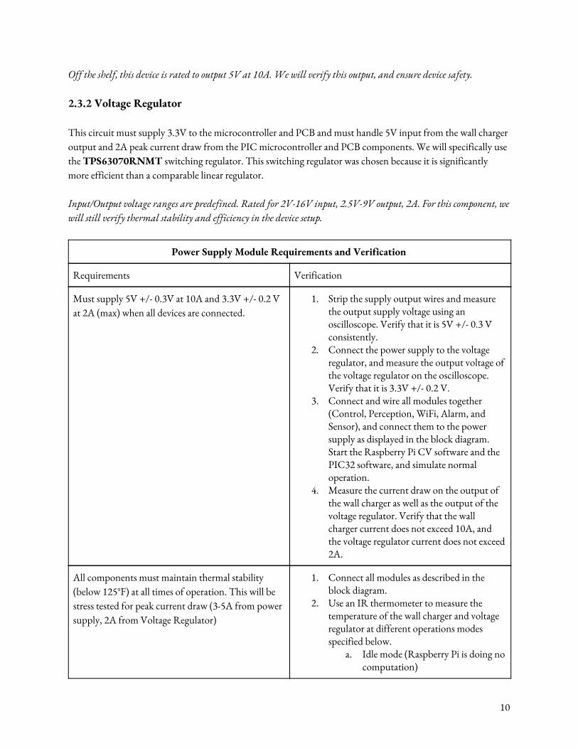
Voltage Regulator must have an efficiency of at least 50% for 2A current draw (from Control, Speaker, WiFi, and Sensor modules). Efficiency does not need to be very high because we do not have a limited battery, although energy consumption is still a concern. Below is the datasheet efficiency vs output graph at Vo = 5V. We will need to verify our efficiencies for Vin = 5V, Vo = 3.3V, Current = 2A
1. Connect all modules as described in the block diagram.
2. Simulate the maximum current draw from the Raspberry Pi and PIC32 by running the complete CV algorithm during computation, and running normal software on the PIC32.
3. Use current and voltage probes to measure the current and voltage on either side of the regulator and plot on an oscilloscope. Compute the average power efficiency over 1 minute.
4. Verify that the efficiencies are within the specified ranges for max current draw during normal usage.
2.4 Perception Module The camera module will allow the device to take images and process them. The camera will take images and transfer this data to the Raspberry Pi. The CPU on the Raspberry Pi will do the image processing, and send data to the PIC microcontroller. This data will consist of simple directives (eg: “package delivered”, “package stolen”, “face recognized”) 2.4.1 Raspberry Pi The device will use a Raspberry Pi 3 for image processing using computer vision (openCV) [5]. The Pi will take image input directly from the camera, process this image on the CPU, and send data out. If an incident occurs, the recording will be stored on the Raspberry Pi. No other portion of the Raspberry Pi will be used. The Raspberry Pi 3 is rated to work with 5V, 2A supply (10A supply will also work).
11
2.4.2. Camera The camera used will be the official Raspberry Pi camera (5 MP, 1080p resolution). The camera must take continuous video when motion is detected, and take periodic frames (2 FPS) when no motion is detected. It will send this image data to the Raspberry Pi for processing as it takes images. The Raspberry Pi Camera is compatible with the Raspberry Pi 3, and can take image and video at both 1080p and 720p.
Perception Module Requirements and Verification
Requirements Verification
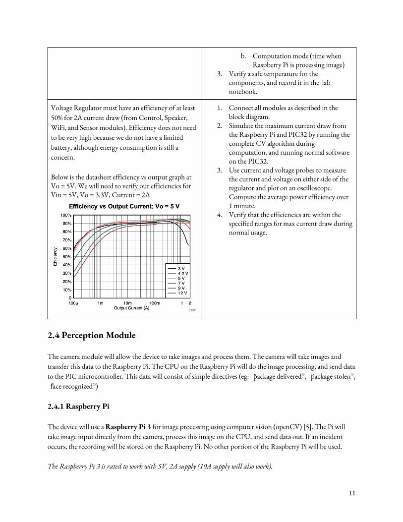
Software must read the image data over CSI bus, process it, and output an initial diagnostic string text in < 3 seconds +/- 2 seconds. (In the event that the Raspberry Pi does not have the processing power to complete this task, this requirement can be relaxed. A finished product may implement GPUs instead to improve speed).
1. Implement the complete Computer Vision algorithm using OpenCV (package and facial recognition).
2. Simulate the following different testing scenarios.
a. A package with a marking is delivered to the center of the field of view.
b. A package is taken by a foreign subject in the center of the field of view.
c. The user does not move the package, but shows their face to the camera.
3. For each scenario, start the timer as soon as the action occurs, and monitor the Raspberry Pi output. Look for a diagnostic output and record the time taken.
4. Repeat step 2-3 for each scenario 10 times, and compute the average time taken for a diagnostic.
Diagnostic output (eg: “THEFT”, “DELIVERY”, “NON-THEFT”) must have a 90% +/- 5% accuracy during thefts, 90% +/- 5% during deliveries, and %80 +/- 5% for user face recognition. The most important metric is that the software accurately detects thefts and does not have a high false negative rate.
1. Implement the complete Computer Vision algorithm using OpenCV (package and facial recognition).
2. Simulate the following different testing scenarios.
a. A package with a marking is delivered to the center of the field of view.
b. A package is taken by a foreign subject in the center of the field of
12
view. c. The user does not move the
package, but shows their face to the camera.
3. For each scenario, evaluate the accuracy of the given diagnostic (binary TRUE or FALSE).
4. Repeat step 2-3 for each scenario 20 times, and compute the accuracy of the diagnostic output. Verify that it falls within the required ranges.
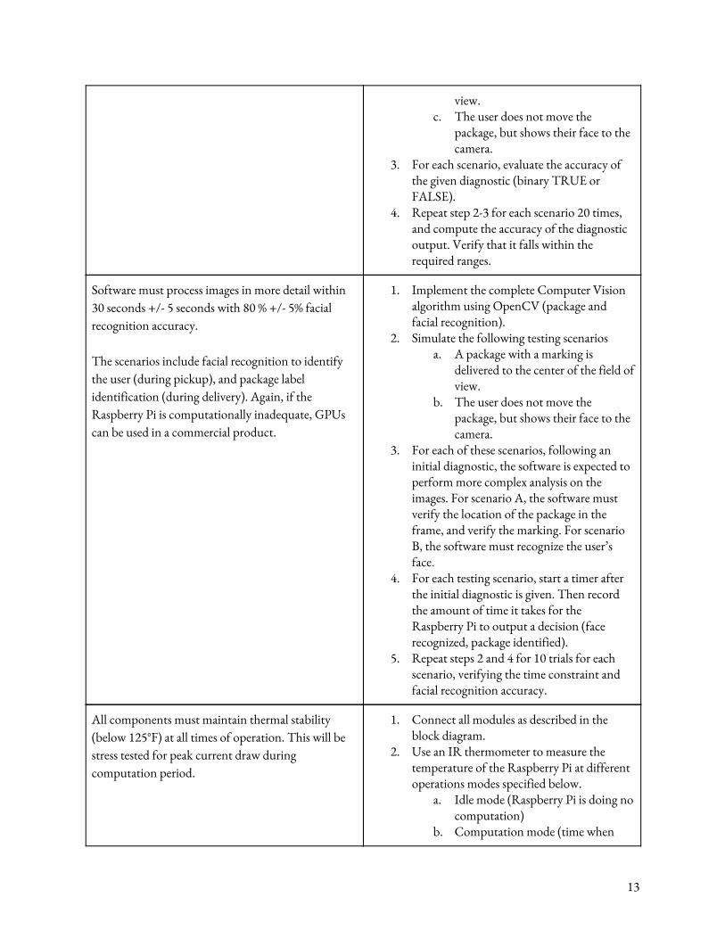
Software must process images in more detail within 30 seconds +/- 5 seconds with 80 % +/- 5% facial recognition accuracy. The scenarios include facial recognition to identify the user (during pickup), and package label identification (during delivery). Again, if the Raspberry Pi is computationally inadequate, GPUs can be used in a commercial product.
1. Implement the complete Computer Vision algorithm using OpenCV (package and facial recognition).
2. Simulate the following testing scenarios a. A package with a marking is
delivered to the center of the field of view.
b. The user does not move the package, but shows their face to the camera.
3. For each of these scenarios, following an initial diagnostic, the software is expected to perform more complex analysis on the images. For scenario A, the software must verify the location of the package in the frame, and verify the marking. For scenario B, the software must recognize the user’s face.
4. For each testing scenario, start a timer after the initial diagnostic is given. Then record the amount of time it takes for the Raspberry Pi to output a decision (face recognized, package identified).
5. Repeat steps 2 and 4 for 10 trials for each scenario, verifying the time constraint and facial recognition accuracy.
All components must maintain thermal stability (below 125°F) at all times of operation. This will be stress tested for peak current draw during computation period.
1. Connect all modules as described in the block diagram.
2. Use an IR thermometer to measure the temperature of the Raspberry Pi at different operations modes specified below.
a. Idle mode (Raspberry Pi is doing no computation)
b. Computation mode (time when
13

Raspberry Pi is processing image) 3. Verify a safe temperature for the
components, and record it in the lab notebook.
2.5 Control Module The control unit needs to process data coming from the Raspberry Pi and the PIR motion sensor, and output audio to the speaker module and string text to the WiFi module. The motion sensor module will alert the control module when motion is detected (within a reasonable threshold), triggering the spotlight if necessary. The Raspberry Pi will immediately start processing images to detect the current action occurring, and will send data back to the microcontroller. On the receipt of this information, the Control module will take action. This action can be:
1. Play an alarm sound, request constant video recording from Raspberry Pi for 30 seconds, and send a text message to the WiFi module indicating a theft.
2. Send a text message to the WiFi module to indicate a delivered package. 3. Play a ringtone on the speaker and reset upon the recognition of the user’s face when he or she picks up
the package. 2.5.1 Microcontroller The microcontroller will be a PIC32, specifically the PIC32MX270F256D, and will communicate with the Raspberry Pi using UART. It will run software that will recognize commands coming from the Raspberry Pi, as well as send signals out on the PWM output and to the WiFi module. The PIC32 micontroller is rated to run on 3.3V and 2A max current.
Control Module Requirements and Verification
Requirements Verification
Communicate with Raspberry Pi over UART for data transfer (send and receive) at > 4.5 Mbps (pins support up to 12.5 Mbps)
1. Connect PIC32 to Raspberry Pi GPIO UART pins, specifically pins 14 and 15.
2. Write a program to generate Random 1 0.45 Mbit data string to send from Raspberry Pi to PIC32.
3. Start a timer, send data from Raspberry Pi to PIC, and send an echo back, stop timer.
4. Verify the time < 200ms, and record this time in the lab notebook to indicate the latency of Raspberry Pi to PIC32.
14
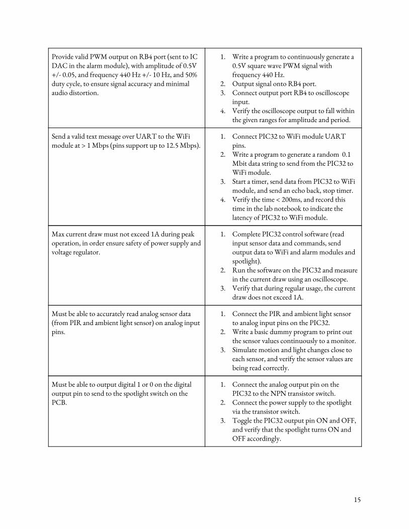
Provide valid PWM output on RB4 port (sent to IC DAC in the alarm module), with amplitude of 0.5V +/- 0.05, and frequency 440 Hz +/- 10 Hz, and 50% duty cycle, to ensure signal accuracy and minimal audio distortion.
1. Write a program to continuously generate a 0.5V square wave PWM signal with frequency 440 Hz.
2. Output signal onto RB4 port. 3. Connect output port RB4 to oscilloscope
input. 4. Verify the oscilloscope output to fall within
the given ranges for amplitude and period.
Send a valid text message over UART to the WiFi module at > 1 Mbps (pins support up to 12.5 Mbps).
1. Connect PIC32 to WiFi module UART pins.
2. Write a program to generate a random 0.1 Mbit data string to send from the PIC32 to WiFi module.
3. Start a timer, send data from PIC32 to WiFi module, and send an echo back, stop timer.
4. Verify the time < 200ms, and record this time in the lab notebook to indicate the latency of PIC32 to WiFi module.
Max current draw must not exceed 1A during peak operation, in order ensure safety of power supply and voltage regulator.
1. Complete PIC32 control software (read input sensor data and commands, send output data to WiFi and alarm modules and spotlight).
2. Run the software on the PIC32 and measure in the current draw using an oscilloscope.
3. Verify that during regular usage, the current draw does not exceed 1A.
Must be able to accurately read analog sensor data (from PIR and ambient light sensor) on analog input pins.
1. Connect the PIR and ambient light sensor to analog input pins on the PIC32.
2. Write a basic dummy program to print out the sensor values continuously to a monitor.
3. Simulate motion and light changes close to each sensor, and verify the sensor values are being read correctly.
Must be able to output digital 1 or 0 on the digital output pin to send to the spotlight switch on the PCB.
1. Connect the analog output pin on the PIC32 to the NPN transistor switch.
2. Connect the power supply to the spotlight via the transistor switch.
3. Toggle the PIC32 output pin ON and OFF, and verify that the spotlight turns ON and OFF accordingly.
15
2.6 Sensor Module The motion sensor module will be required to detect motion, measure ambient light, trigger a spotlight, and communicate to the microcontroller. In order to do this, the PIR sensor will send its data to the microcontroller in real time, which will process this data to detect motion above a certain threshold. The sensor module will also detect ambient light, and will trigger the spotlight if the ambient light is below a certain threshold and motion is detected, indicating an event occuring in the dark. 2.6.1 PIR Sensor The PIR sensor will be directly connected to the microcontroller, and will output analog data into the PIC analog input pin. The PIR sensor will work in daylight or nighttime, and will need to alert the system if any human movement occurs in the field of view. We will use the EKMB1101111 PIR Sensor. The EKMB1101111 is rated for very low current consumption (1-6 uA). 2.6.2 Ambient Light Sensor The ambient light sensor will be directly connected to the microcontroller as well, and will constantly measure the amount of ambient light in the package drop-off area. If the ambient light is above the threshold, there is high visibility which means the spotlight is not needed. Above this threshold, the camera should be able to capture potential thieves and detect the package easily. Once the ambient light drops below this threshold, visibility will start to decrease, making it harder for the camera to detect the package and capture thieves. Once the ambient light drops below this threshold, the spotlight will begin to be triggered when the PIR sensor detects motion. We will use the APDS-9007-020 Light Sensor. The APDS-9007-020 will run on 3.3V input, and has a “photo current response to wide dynamic range of 3 lux to 70K lux”. 2.6.3 Spotlight The spotlight will be powered by the main power supply, and will be turned ON and OFF by the microcontroller. The microcontroller will control an external switch, which will be ON when it is nighttime and motion is detected (PIR sensor and Ambient Light Sensor). We will use a disassembled flashlight, specifically a Maglite LED Flashlight. The maglite LED flashlight will run on 5V input voltage, and max current will not exceed 1.5A. 2.6.4 Transistor Switch In order to turn the spotlight ON and OFF, we will be using an NPN transistor that will be controlled by the PIC32 micrcocontoller. The specific transistor we are using is the KTD1624.
16
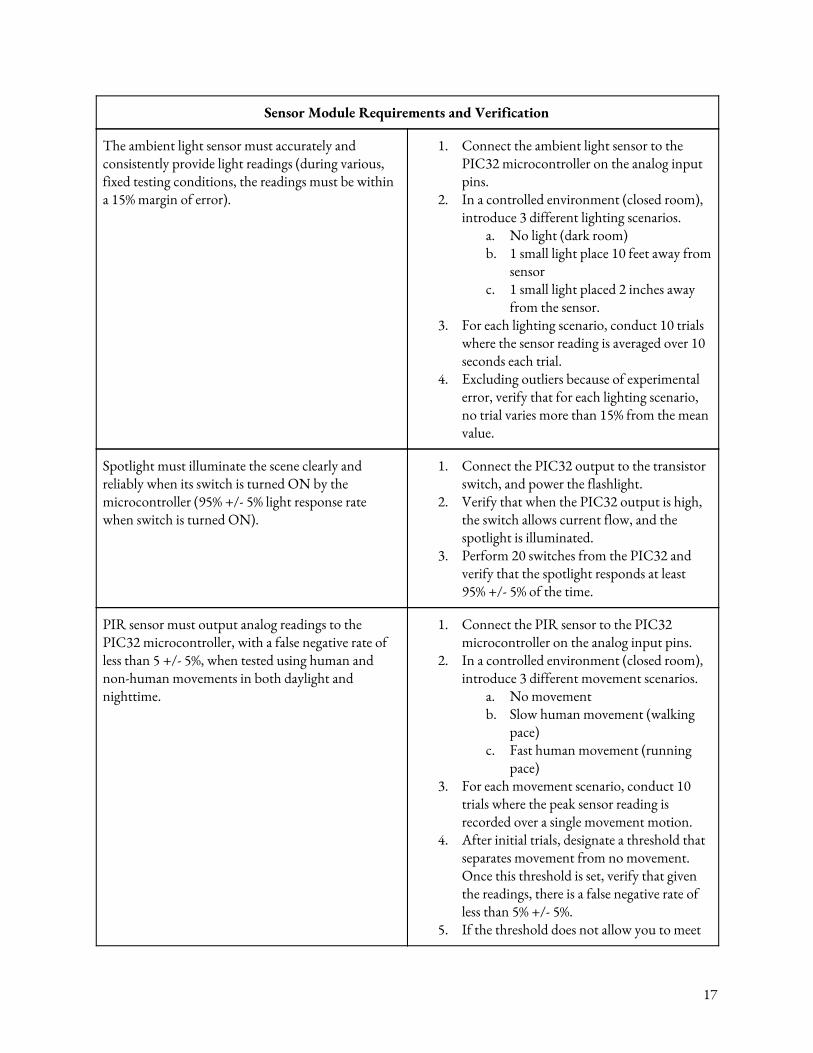
Sensor Module Requirements and Verification
The ambient light sensor must accurately and consistently provide light readings (during various, fixed testing conditions, the readings must be within a 15% margin of error).
1. Connect the ambient light sensor to the PIC32 microcontroller on the analog input pins.
2. In a controlled environment (closed room), introduce 3 different lighting scenarios.
a. No light (dark room) b. 1 small light place 10 feet away from
sensor c. 1 small light placed 2 inches away
from the sensor. 3. For each lighting scenario, conduct 10 trials
where the sensor reading is averaged over 10 seconds each trial.
4. Excluding outliers because of experimental error, verify that for each lighting scenario, no trial varies more than 15% from the mean value.
Spotlight must illuminate the scene clearly and reliably when its switch is turned ON by the microcontroller (95% +/- 5% light response rate when switch is turned ON).
1. Connect the PIC32 output to the transistor switch, and power the flashlight.
2. Verify that when the PIC32 output is high, the switch allows current flow, and the spotlight is illuminated.
3. Perform 20 switches from the PIC32 and verify that the spotlight responds at least 95% +/- 5% of the time.
PIR sensor must output analog readings to the PIC32 microcontroller, with a false negative rate of less than 5 +/- 5%, when tested using human and non-human movements in both daylight and nighttime.
1. Connect the PIR sensor to the PIC32 microcontroller on the analog input pins.
2. In a controlled environment (closed room), introduce 3 different movement scenarios.
a. No movement b. Slow human movement (walking
pace) c. Fast human movement (running
pace) 3. For each movement scenario, conduct 10
trials where the peak sensor reading is recorded over a single movement motion.
4. After initial trials, designate a threshold that separates movement from no movement. Once this threshold is set, verify that given the readings, there is a false negative rate of less than 5% +/- 5%.
5. If the threshold does not allow you to meet
17
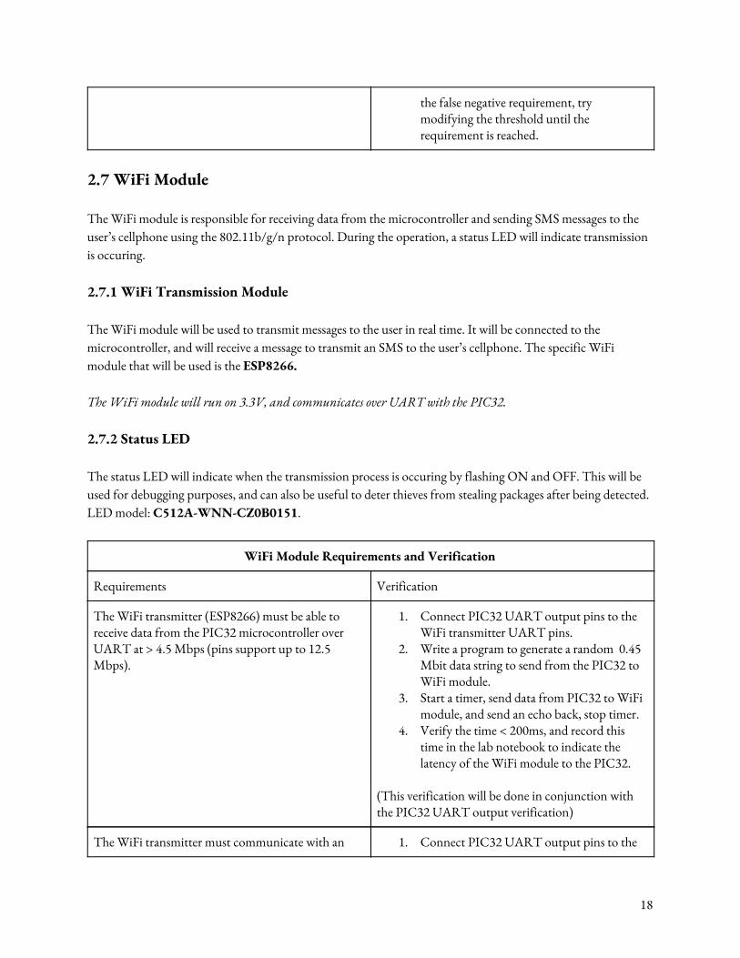
the false negative requirement, try modifying the threshold until the requirement is reached.
2.7 WiFi Module The WiFi module is responsible for receiving data from the microcontroller and sending SMS messages to the user’s cellphone using the 802.11b/g/n protocol. During the operation, a status LED will indicate transmission is occuring. 2.7.1 WiFi Transmission Module The WiFi module will be used to transmit messages to the user in real time. It will be connected to the microcontroller, and will receive a message to transmit an SMS to the user’s cellphone. The specific WiFi module that will be used is the ESP8266. The WiFi module will run on 3.3V, and communicates over UART with the PIC32. 2.7.2 Status LED The status LED will indicate when the transmission process is occuring by flashing ON and OFF. This will be used for debugging purposes, and can also be useful to deter thieves from stealing packages after being detected. LED model: C512A-WNN-CZ0B0151.
WiFi Module Requirements and Verification
Requirements Verification
The WiFi transmitter (ESP8266) must be able to receive data from the PIC32 microcontroller over UART at > 4.5 Mbps (pins support up to 12.5 Mbps).
1. Connect PIC32 UART output pins to the WiFi transmitter UART pins.
2. Write a program to generate a random 0.45 Mbit data string to send from the PIC32 to WiFi module.
3. Start a timer, send data from PIC32 to WiFi module, and send an echo back, stop timer.
4. Verify the time < 200ms, and record this time in the lab notebook to indicate the latency of the WiFi module to the PIC32.
(This verification will be done in conjunction with the PIC32 UART output verification)
The WiFi transmitter must communicate with an 1. Connect PIC32 UART output pins to the
18
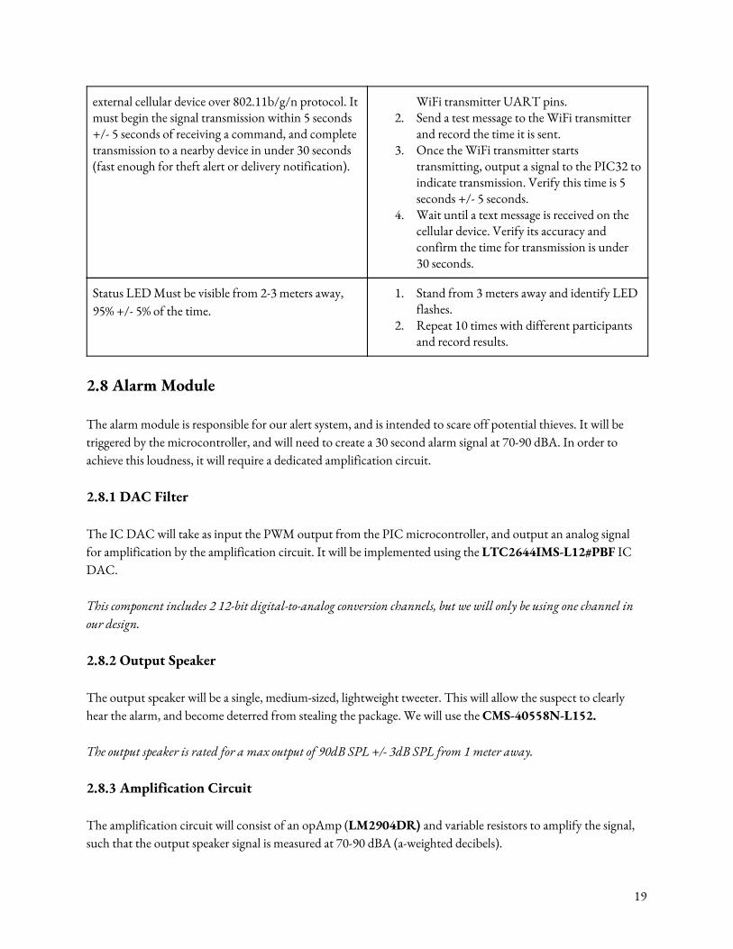
external cellular device over 802.11b/g/n protocol. It must begin the signal transmission within 5 seconds +/- 5 seconds of receiving a command, and complete transmission to a nearby device in under 30 seconds (fast enough for theft alert or delivery notification).
WiFi transmitter UART pins. 2. Send a test message to the WiFi transmitter
and record the time it is sent. 3. Once the WiFi transmitter starts
transmitting, output a signal to the PIC32 to indicate transmission. Verify this time is 5 seconds +/- 5 seconds.
4. Wait until a text message is received on the cellular device. Verify its accuracy and confirm the time for transmission is under 30 seconds.
Status LED Must be visible from 2-3 meters away, 95% +/- 5% of the time.
1. Stand from 3 meters away and identify LED flashes.
2. Repeat 10 times with different participants and record results.
2.8 Alarm Module The alarm module is responsible for our alert system, and is intended to scare off potential thieves. It will be triggered by the microcontroller, and will need to create a 30 second alarm signal at 70-90 dBA. In order to achieve this loudness, it will require a dedicated amplification circuit. 2.8.1 DAC Filter The IC DAC will take as input the PWM output from the PIC microcontroller, and output an analog signal for amplification by the amplification circuit. It will be implemented using the LTC2644IMS-L12#PBF IC DAC. This component includes 2 12-bit digital-to-analog conversion channels, but we will only be using one channel in our design. 2.8.2 Output Speaker The output speaker will be a single, medium-sized, lightweight tweeter. This will allow the suspect to clearly hear the alarm, and become deterred from stealing the package. We will use the CMS-40558N-L152. The output speaker is rated for a max output of 90dB SPL +/- 3dB SPL from 1 meter away. 2.8.3 Amplification Circuit The amplification circuit will consist of an opAmp (LM2904DR) and variable resistors to amplify the signal, such that the output speaker signal is measured at 70-90 dBA (a-weighted decibels).
19
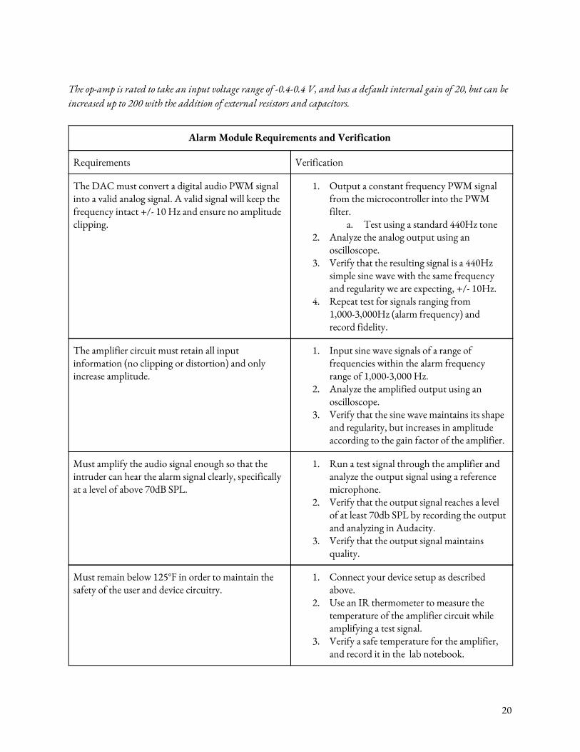
The op-amp is rated to take an input voltage range of -0.4-0.4 V, and has a default internal gain of 20, but can be increased up to 200 with the addition of external resistors and capacitors.
Alarm Module Requirements and Verification
Requirements Verification
The DAC must convert a digital audio PWM signal into a valid analog signal. A valid signal will keep the frequency intact +/- 10 Hz and ensure no amplitude clipping.
1. Output a constant frequency PWM signal from the microcontroller into the PWM filter.
a. Test using a standard 440Hz tone 2. Analyze the analog output using an
oscilloscope. 3. Verify that the resulting signal is a 440Hz
simple sine wave with the same frequency and regularity we are expecting, +/- 10Hz.
4. Repeat test for signals ranging from 1,000-3,000Hz (alarm frequency) and record fidelity.
The amplifier circuit must retain all input information (no clipping or distortion) and only increase amplitude.
1. Input sine wave signals of a range of frequencies within the alarm frequency range of 1,000-3,000 Hz.
2. Analyze the amplified output using an oscilloscope.
3. Verify that the sine wave maintains its shape and regularity, but increases in amplitude according to the gain factor of the amplifier.
Must amplify the audio signal enough so that the intruder can hear the alarm signal clearly, specifically at a level of above 70dB SPL.
1. Run a test signal through the amplifier and analyze the output signal using a reference microphone.
2. Verify that the output signal reaches a level of at least 70db SPL by recording the output and analyzing in Audacity.
3. Verify that the output signal maintains quality.
Must remain below 125°F in order to maintain the safety of the user and device circuitry.
1. Connect your device setup as described above.
2. Use an IR thermometer to measure the temperature of the amplifier circuit while amplifying a test signal.
3. Verify a safe temperature for the amplifier, and record it in the lab notebook.
20
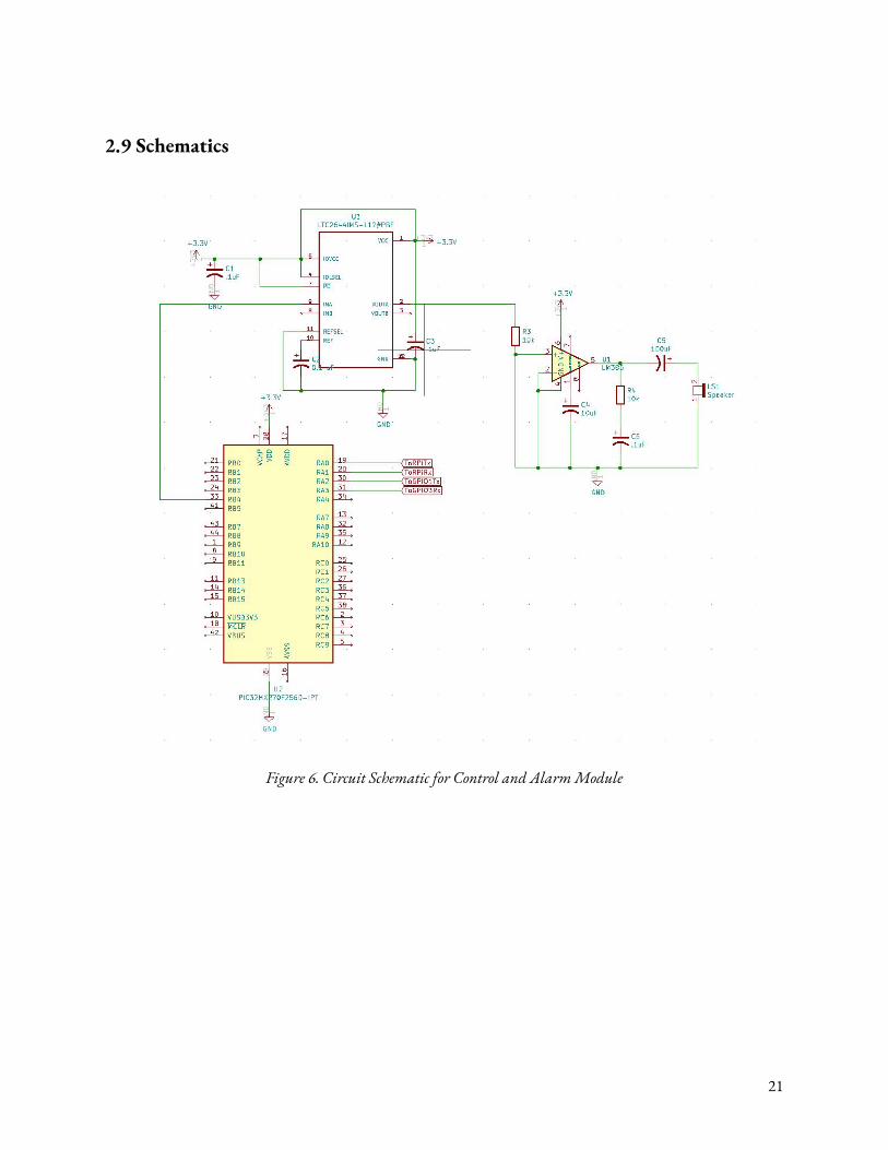
2.9 Schematics
Figure 6. Circuit Schematic for Control and Alarm Module
21
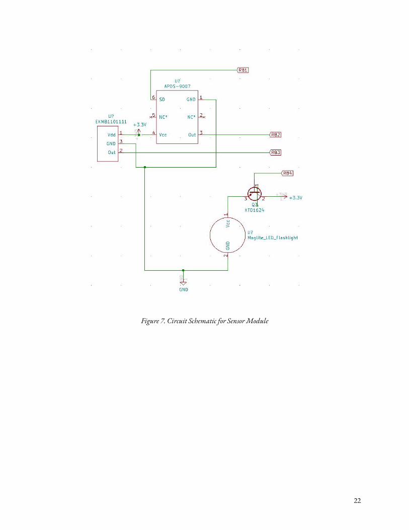
Figure 7. Circuit Schematic for Sensor Module
22
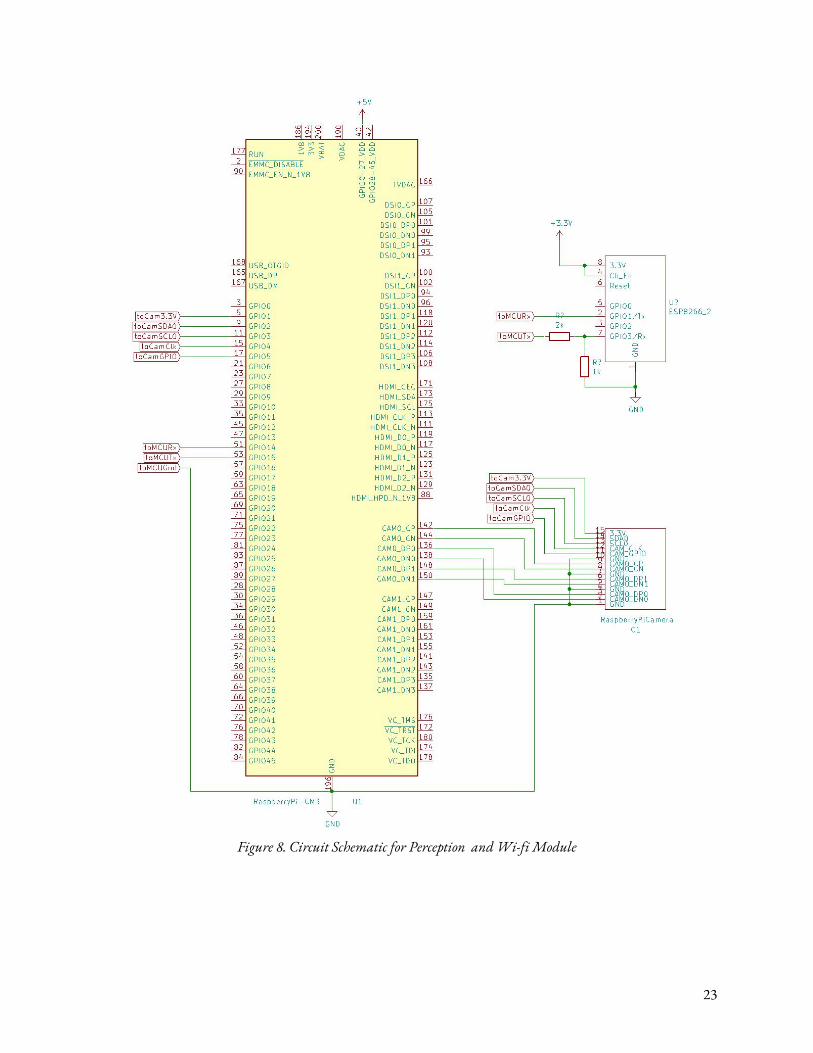
Figure 8. Circuit Schematic for Perception and Wi-fi Module
23
2.10 Software The software component of our product will be split into two main computational components. The first is the computer vision package and facial recognition model that will run on the Raspberry Pi. The second is the reading of sensor data and directives from the Raspberry Pi, and making decisions to transmit messages, sound an alarm, or turn on the spotlight. This will happen on the microcontroller. 2.10.1 Computer Vision Package and Facial Recognition We will be using OpenCV in order to complete both computer vision tasks. In order to process images in real time, we will be taking a few snapshots every second (instead of continuous video). When each snapshot comes in, it will need to be processed by the software. In order to identify packages, we will use a distinct marking on the package, something that is easy to see and recognize. We will train our model to recognize this marking, and if it appears on a snapshot, this indicates that a package has been delivered. After the completion of the delivery, every subsequent snapshot must have the marking visible, or a signal will be sent indicating a theft. In cases when motion is detected, the Raspberry Pi will switch to video mode where it will record continuous frames and save them on the SD card (while still only processing snapshots for recognition purpose). This can be expanded to store video on the cloud for increased security and data accessibility. This video recording is useful for the user in the case of a theft. For facial recognition, instead of using conventional convolution neural nets, we will use “Haar cascades”, a more dated facial recognition method that will run better on the Raspberry Pi. There is specific documentation [7] that explains the way in which this algorithm can be implemented on a Raspberry Pi, running at around 8-10 FPS during video recording. This method will allow us to identify faces in the frame, run our facial recognition algorithm, and disarm our system. 2.10.2 Micrcontoller Dispatcher The microcontroller’s software will essentially consist of a looping mechanism that interacts with the I/O channels at each timestep. The inputs will come from the Raspberry Pi and the sensors. Any time that the ambient light sensor detects low light and PIR detects motion, the microcontroller will flip the switch on the spotlight to turn it on. When the microcontroller receives a directive from the Raspberry Pi (eg: “THEFT”, “DELIVERY”), it will communicate with the WiFi module to send an appropriate text to the user. Simultaneously, it will also output a PWM alarm signal to the alarm module if necessary. This code will be a simple set of if else statements and port connections, that will handle the transfer of data across the device.
2.11 Tolerance Analysis The success of the project is determined by the reliability of our perception and sensor module in tracking a package and detecting the presence of other objects within a scene with varying lighting conditions. To successfully achieve this, we require our system to be robust enough to tolerate a range of operating conditions.
24
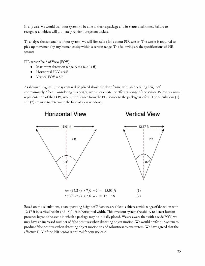
In any case, we would want our system to be able to track a package and its status at all times. Failure to recognize an object will ultimately render our system useless. To analyze the constraints of our system, we will first take a look at our PIR sensor. The sensor is required to pick up movement by any human entity within a certain range. The following are the specifications of PIR sensor: PIR sensor Field of View (FOV):
● Maximum detection range: 5 m (16.404 ft) ● Horizontal FOV = 94° ● Vertical FOV = 82°
As shown in Figure 1, the system will be placed above the door frame, with an operating height of approximately 7 feet. Considering this height, we can calculate the effective range of the sensor. Below is a visual representation of the FOV, when the distance from the PIR sensor to the package is 7 feet. The calculations (1) and (2) are used to determine the field of view window.
an (94/2 ) f t 15.01 f tt ° * 7 * 2 = (1) an (82/2 ) f t 12.17 f tt ° * 7 * 2 = (2)
Based on the calculations, at an operating height of 7 feet, we are able to achieve a wide range of detection with 12.17 ft in vertical height and 15.01 ft in horizontal width. This gives our system the ability to detect human presence beyond the scene in which a package may be initially placed. We are aware that with a wide FOV, we may have an increased number of false positives when detecting object motion. We would prefer our system to produce false positives when detecting object motion to add robustness to our system. We have agreed that the effective FOV of the PIR sensor is optimal for our use case.
25
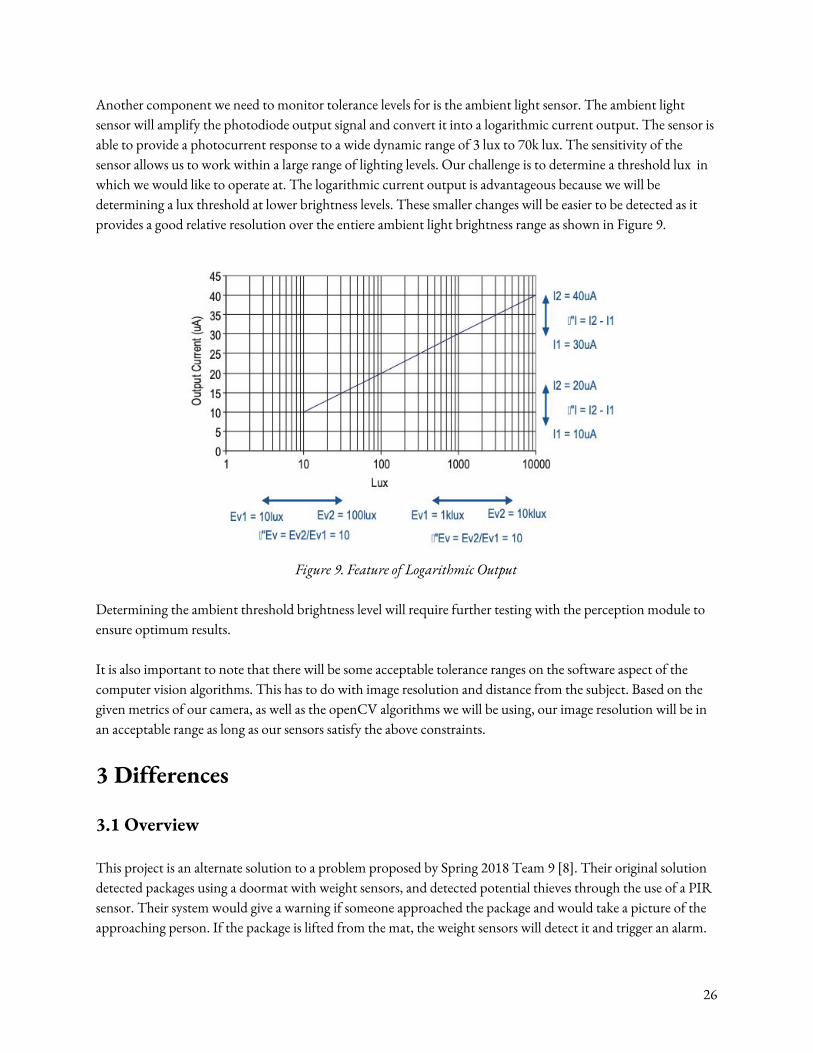
Another component we need to monitor tolerance levels for is the ambient light sensor. The ambient light sensor will amplify the photodiode output signal and convert it into a logarithmic current output. The sensor is able to provide a photocurrent response to a wide dynamic range of 3 lux to 70k lux. The sensitivity of the sensor allows us to work within a large range of lighting levels. Our challenge is to determine a threshold lux in which we would like to operate at. The logarithmic current output is advantageous because we will be determining a lux threshold at lower brightness levels. These smaller changes will be easier to be detected as it provides a good relative resolution over the entiere ambient light brightness range as shown in Figure 9.
Figure 9. Feature of Logarithmic Output
Determining the ambient threshold brightness level will require further testing with the perception module to ensure optimum results. It is also important to note that there will be some acceptable tolerance ranges on the software aspect of the computer vision algorithms. This has to do with image resolution and distance from the subject. Based on the given metrics of our camera, as well as the openCV algorithms we will be using, our image resolution will be in an acceptable range as long as our sensors satisfy the above constraints.
3 Differences
3.1 Overview This project is an alternate solution to a problem proposed by Spring 2018 Team 9 [8]. Their original solution detected packages using a doormat with weight sensors, and detected potential thieves through the use of a PIR sensor. Their system would give a warning if someone approached the package and would take a picture of the approaching person. If the package is lifted from the mat, the weight sensors will detect it and trigger an alarm.
26
If an alarm is triggered, the system will notify the user by sending a notification containing the captured photo to an Android app that is connected to this system over WiFi. The system is disabled using the app, or an RFID tag. Our solution is different in a few key ways. First, our system uses only one camera to detect and track a package. Team 9’s solution contains a camera, but also includes a weight sensor mat. We believe the mat is redundant and unnecessary if the goal is to detect and track a package. This can be done using the camera alone through computer vision. Eliminating the doormat also allows the package to be placed in a wider area in your entryway. The old design will only work if the package is placed upon the doormat, but our solution will function as long as the package is in view of the camera mounted above the door. The field of view of the camera will be much wider than the doormat, making our solution more flexible and robust. Next, our design will be entirely housed in one unit that is mounted above your door, instead of having separate units on the floor and above the door. Having the whole system in one enclosed body reduces the risk of tampering with the system. Another difference is that if motion is detected near the package, our system will record a short video clip instead of just a picture. A video clip will give more context and information surrounding events in which an alarm is triggered. Our system will be disabled using facial recognition instead of an RFID tag as well, which further reduces cost because using facial recognition does not require any additional hardware, and will simply require software computation. Finally, our system does not need a dedicated app, and will instead send the user a text when packages are delivered, or if activity is detected. This will make the system more flexible for different users with different types of smartphones.
3.2 Analysis The differences listed all work to make our package security system a better, more effective solution to the pervasive problem of package theft. By restructuring the system into a single package that utilizes computer vision to monitor packages when delivered solves several problem points of the old system. The most important improvements of our system relate to usability and simplicity. One deficiency of the original project design is the weight sensor mat. There are obvious limitations of this feature when it comes to usability and security, both of which are important factors for consumers when purchasing security systems. If a package is not placed within the bounds of the mat, it will not be detected, making the system essentially useless. In our system, the package can be placed anywhere within the field of the view of the camera, which is a much wider range. Secondly, the weight sensor can trigger false alarms if some foreign object like a leaf or branch happened to land on the mat. This is not an issue for our improved design, because our computer vision system is constantly looking for the package itself rather than a specific weight. Another aspect that we have improved is the method of disarming the alarm when you want to retrieve your package. In the original design, the user had to use an Android app or an RFID tag to disarm the alarm and pick up their package. This method works perfectly fine, but adds an extra layer of complexity to the process of picking up a package. Using the app requires you to take out your phone and navigate to the app, and using an RFID tag requires you to carry another physical item with you at all times. Our solution to this problem is to use the existing camera and incorporate a face recognition model to disarm the system. This does not require the
27

user to access their phone or carry any additional hardware. It will function seamlessly, and greatly improves the simplicity and utility of the product. Overall, the features discussed are all extremely important to consumers when deciding to purchase a security system. Focusing on usability and simplicity make our product more enjoyable and painless to use, while maintaining robust security features that protect our customers’ packages. Our improvements on the original product make it a better value and experience for the user.
4 Cost and Schedule
4.1 Cost Analysis In the academic year ‘14-’15, the average salary of a student who graduated with a BS in Computer Engineering was $84,250/year [11]. Dividing the salary by the amount of work hours in a year, 2080 hrs/year, we arrive at an hourly rate of $40.50/hour. We will assume that an employee will work 8 hours a day every week for 16 weeks. We arrive at a total of 128 hours to complete the project.
Table 1. Expected labor cost of a single employee
Employee Rate Hours Labor Factor Labor Cost
Employee X $40.50 128 2.5 $12,960
Given that our team consists of 3 members, our total labor cost to complete the project is $38,880.
4.2 Parts Acquisition
Table 2. Breakdown of parts required with expenses
Module Parts Cost Per Unit
Reason
Control PIC32MX270F256D
Microcontroller $4.09 Microcontroller for managing peripherals and
I/O
Power Supply 5V 10A Wall Charger $19.88 Provide 5V power
Voltage Regulator $2.77 5V to 3.3V converter
Perception Raspberry Pi $35.00 Perform computer vision component
Raspberry Pi Camera Module v2 $25.25 Image/Video input
Speaker
PCB 8 Ohm Speaker $2.50 Audio output
LM386 Op Amp $1.05 Amplification circuit
28
IC DAC $7.21 Digital to analog converter
Wi-fi ESP8266 Wi-fi module $6.95 Enable wifi capabilities for microcontroller
Sensor
PIR Sensor $2.29 Motion detection
APDS-9007-020 Light Sensor $2.07 Ambient light detection
Maglite LED Flashlight $24.98 Spotlight for illumination
Grand Total $134.04
The grand total for the completion of the project is $38,880 + $134.04 = $39,014.04.
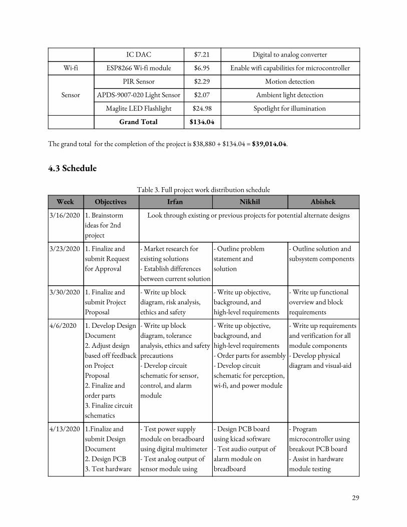
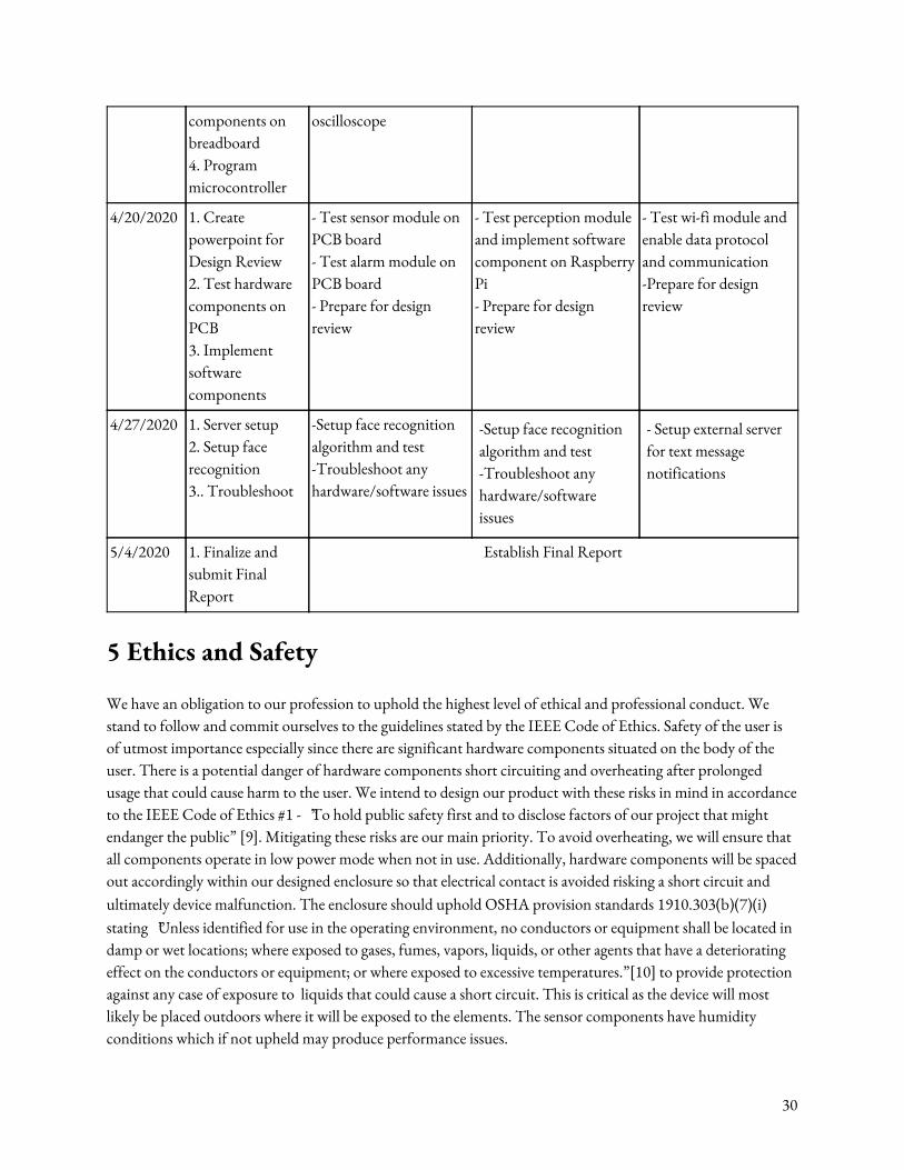
4.3 Schedule
Table 3. Full project work distribution schedule
Week Objectives Irfan Nikhil Abishek
3/16/2020 1. Brainstorm ideas for 2nd project
Look through existing or previous projects for potential alternate designs
3/23/2020 1. Finalize and submit Request for Approval
- Market research for existing solutions - Establish differences between current solution
- Outline problem statement and solution
- Outline solution and subsystem components
3/30/2020 1. Finalize and submit Project Proposal
- Write up block diagram, risk analysis, ethics and safety
- Write up objective, background, and high-level requirements
- Write up functional overview and block requirements
4/6/2020 1. Develop Design Document 2. Adjust design based off feedback on Project Proposal 2. Finalize and order parts 3. Finalize circuit schematics
- Write up block diagram, tolerance analysis, ethics and safety precautions - Develop circuit schematic for sensor, control, and alarm module
- Write up objective, background, and high-level requirements - Order parts for assembly - Develop circuit schematic for perception, wi-fi, and power module
- Write up requirements and verification for all module components - Develop physical diagram and visual-aid
4/13/2020 1.Finalize and submit Design Document 2. Design PCB 3. Test hardware
- Test power supply module on breadboard using digital multimeter - Test analog output of sensor module using
- Design PCB board using kicad software - Test audio output of alarm module on breadboard
- Program microcontroller using breakout PCB board - Assist in hardware module testing
29
components on breadboard 4. Program microcontroller
oscilloscope
4/20/2020 1. Create powerpoint for Design Review 2. Test hardware components on PCB 3. Implement software components
- Test sensor module on PCB board - Test alarm module on PCB board - Prepare for design review
- Test perception module and implement software component on Raspberry Pi - Prepare for design review
- Test wi-fi module and enable data protocol and communication -Prepare for design review
4/27/2020 1. Server setup 2. Setup face recognition 3.. Troubleshoot
-Setup face recognition algorithm and test -Troubleshoot any hardware/software issues
-Setup face recognition algorithm and test -Troubleshoot any hardware/software issues
- Setup external server for text message notifications
5/4/2020 1. Finalize and submit Final Report
Establish Final Report
5 Ethics and Safety We have an obligation to our profession to uphold the highest level of ethical and professional conduct. We stand to follow and commit ourselves to the guidelines stated by the IEEE Code of Ethics. Safety of the user is of utmost importance especially since there are significant hardware components situated on the body of the user. There is a potential danger of hardware components short circuiting and overheating after prolonged usage that could cause harm to the user. We intend to design our product with these risks in mind in accordance to the IEEE Code of Ethics #1 - “To hold public safety first and to disclose factors of our project that might endanger the public” [9]. Mitigating these risks are our main priority. To avoid overheating, we will ensure that all components operate in low power mode when not in use. Additionally, hardware components will be spaced out accordingly within our designed enclosure so that electrical contact is avoided risking a short circuit and ultimately device malfunction. The enclosure should uphold OSHA provision standards 1910.303(b)(7)(i) stating “Unless identified for use in the operating environment, no conductors or equipment shall be located in damp or wet locations; where exposed to gases, fumes, vapors, liquids, or other agents that have a deteriorating effect on the conductors or equipment; or where exposed to excessive temperatures.”[10] to provide protection against any case of exposure to liquids that could cause a short circuit. This is critical as the device will most likely be placed outdoors where it will be exposed to the elements. The sensor components have humidity conditions which if not upheld may produce performance issues.
30
We acknowledge that there is a certain degree of error that can arise from object identification. The core of the project depends on users being able to trust our system to identify and label an object in its scene with a high level of accuracy. To adhere to the IEEE Code of Ethics #3 - “To be honest and realistic in stating claims or estimates based on the available data.”[9], it is our duty to be honest of the estimates provided from the available data provided to us. To uphold this, we will ensure that our system has a reliable output and is able to verify and identify different packages. This will be done by training our object recognition model extensively with a variety of packages of all shapes and sizes. In addition, we will also be using a facial recognition algorithm to authorize user access to the system. This will require a significant degree of accuracy as to ensure proper access is given to authorized users. The standard of accuracy in which we will be aiming for will be high to ensure the overall security of our anti-theft system. Finally, our product would not be possible without the advances in computer vision algorithms developed by pioneers before us. In accordance to the IEEE Code of Ethics #7 - “To seek, accept, and offer honest criticism of technical work, to acknowledge and correct errors, and to credit properly the contributions of others.” [9], we would like to formally acknowledge and give due credit to those who have contributed to the open source software, OpenCV.
31
References [1] K. Buchholz and F. Richter, “Infographic: 87 Billion Parcels Were Shipped in 2018,” Statista
Infographics, 08-Nov-2019. [Online]. Available: https://www.statista.com/chart/10922/parcel-shipping-volume-and-parcel-spend-in-selected-countries/. [Accessed: 03-Apr-2020].
[2] Kaza, “6 Shocking Stats about Package Theft,” Smiota, 17-Feb-2020. [Online]. Available:
https://smiota.com/resources/6-shocking-stats-package-theft/. [Accessed: 03-Apr-2020]. [3] “Burglary Statistics: The Hard Numbers,” National Council For Home Safety and Security, 19-Dec-2019.
[Online]. Available: https://www.alarms.org/burglary-statistics/. [Accessed: 03-Apr-2020]. [4] “5 Reasons Why Homeowners Don't Have Home Security Systems,” ADT Home Security and Alarm
Systems | ProtectYourHome.com. [Online]. Available: https://www.protectyourhome.com/blog/articles/2014/march/5-reasons-why-homeowners-dont-have-home-security-systems. [Accessed: 03-Apr-2020].
[5] H. Blodget, “Here's A Picture Of Amazon Locker, The New Delivery Box Amazon Is Using To Take
Over The World,” Business Insider, 24-Aug-2012. [Online]. Available: https://www.businessinsider.com/amazon-locker-2012-8. [Accessed: 03-Apr-2020].
[6] T. Haselton, “Amazon Key changes how packages are delivered - just beware of your dog,” CNBC,
16-Nov-2017. [Online]. Available: https://www.cnbc.com/2017/11/16/amazon-key-in-home-delivery-review.html. [Accessed: 03-Apr-2020].
[7] A. Rosebrock, “Raspberry Pi Face Recognition,” PyImageSearch, 25-Jun-2018. [Online]. Available:
https://www.pyimagesearch.com/2018/06/25/raspberry-pi-face-recognition/. [Accessed: 17-Apr-2020]. [8] J. Bianco, J. Graft, and J. Simonaitis, “Package Anti-Theft System,” Feb. 2018. [Online]. Available:
https://courses.engr.illinois.edu/ece445/getfile.asp?id=12482. [Accessed: 03-April-2020]. [9] “IEEE Code of Ethics,” IEEE. [Online]. Available:
https://www.ieee.org/about/corporate/governance/p7-8.html. [Accessed: 03-Apr-2020]. [10] Osha.gov. (2020). 1910.303 - General. | Occupational Safety and Health Administration. [online]
Available at: https://www.osha.gov/laws-regs/regulations/standardnumber/1910/1910.303 [Accessed 28 Feb. 2020].
32