A Multiplexing Scheme for Multimodal Teleoperation · the available transmission rate in real time...
29
A Multiplexing Scheme for Multimodal Teleoperation BURAK CIZMECI, XIAO XU, RAHUL CHAUDHARI, CHRISTOPH BACHHUBER, NICOLAS ALT and ECKEHARD STEINBACH, Chair of Media Technology Technical University of Munich Munich, Germany This paper proposes an application-layer multiplexing scheme for teleoperation systems with multimodal feedback (video, audio and haptics). The available transmission resources are carefully allocated to avoid delay-jitter for the haptic signal potentially caused by the size and arrival time of the video and audio data. The multiplexing scheme gives high priority to the haptic signal and applies a preemptive-resume scheduling strategy to stream the audio and video data. The proposed approach estimates the available transmission rate in real time and adapts the video bitrate, data throughput and force buffer size accordingly. Furthermore, the proposed scheme detects sudden transmission rate drops and applies congestion control to avoid abrupt delay increases and converge promptly to the altered transmission rate. The performance of the proposed scheme is measured objectively in terms of end-to-end signal latencies, packet rates and peak signal to noise ratio (PSNR) for visual quality. Moreover, peak-delay and convergence time measurements are carried out to investigate the performance of the congestion control mode of the system. Categories and Subject Descriptors: C.2.1.g [Communication/Networking and Information Technology] Network com- munications; H.1.2 [Models and Principles]: User/Machine Systems—Human Information Processing; H.5.2 [Information Interfaces and Presentation]: User Interfaces—Evaluation/methodology Additional Key Words and Phrases: Haptics, haptic compression and communication, teleoperation, human-robot interaction over communication networks, multiplexing, congestion control, rate control ACM Reference Format: B. Cizmeci, X. Xu, R. Chaudhari, C. Bachhuber, N. Alt and E. Steinbach, A Multiplexing Scheme for Multimodal Teleoperation, ACM Trans. Multimedia Comput. Commun. Appl. 0, 0, Article 0 (March 2017), 29 pages. DOI = 10.1145/0000000.0000000 http://doi.acm.org/10.1145/0000000.0000000 1. INTRODUCTION With a teleoperation system, it is possible to immerse ourselves into environments which are remote or inaccessible to human beings. Teleoperation systems are also referred to as telemanipulation sys- c 2017 ACM TOMM. Personal use of this material is permitted. Permission from ACM must be obtained for all other uses, in any current or future media, including reprinting/republishing this material for advertising or promotional purposes, creating new collective works, for resale or redistribution to servers or lists, or reuse of any copyrighted component of this work in other works. This work has been supported by the European Research Council under the European Union’s Seventh Framework Programme (FP7/2007- 2013) / ERC Grant agreement no. 258941. corresponding author e-mail: [email protected] Permission to make digital or hard copies of part or all of this work for personal or classroom use is granted without fee provided that copies are not made or distributed for profit or commercial advantage and that copies show this notice on the first page or initial screen of a display along with the full citation. Copyrights for components of this work owned by others than ACM must be honored. Abstracting with credit is permitted. To copy otherwise, to republish, to post on servers, to redistribute to lists, or to use any component of this work in other works requires prior specific permission and/or a fee. Permissions may be requested from Publications Dept., ACM, Inc., 2 Penn Plaza, Suite 701, New York, NY 10121-0701 USA, fax +1 (212) 869-0481, or [email protected]. c 2017 ACM 1551-6857/2017/03-ART0 $10.00 DOI 10.1145/0000000.0000000 http://doi.acm.org/10.1145/0000000.0000000 ACM Transactions on Multimedia Computing, Communications and Applications, Vol. 0, No. 0, Article 0, Publication date: March 2017.
Transcript of A Multiplexing Scheme for Multimodal Teleoperation · the available transmission rate in real time...

A Multiplexing Scheme for Multimodal TeleoperationBURAK CIZMECI, XIAO XU, RAHUL CHAUDHARI, CHRISTOPH BACHHUBER, NICOLAS ALTand ECKEHARD STEINBACH,Chair of Media TechnologyTechnical University of MunichMunich, Germany
This paper proposes an application-layer multiplexing scheme for teleoperation systems with multimodal feedback (video, audioand haptics). The available transmission resources are carefully allocated to avoid delay-jitter for the haptic signal potentially
caused by the size and arrival time of the video and audio data. The multiplexing scheme gives high priority to the haptic signal
and applies a preemptive-resume scheduling strategy to stream the audio and video data. The proposed approach estimatesthe available transmission rate in real time and adapts the video bitrate, data throughput and force buffer size accordingly.
Furthermore, the proposed scheme detects sudden transmission rate drops and applies congestion control to avoid abrupt
delay increases and converge promptly to the altered transmission rate. The performance of the proposed scheme is measuredobjectively in terms of end-to-end signal latencies, packet rates and peak signal to noise ratio (PSNR) for visual quality.
Moreover, peak-delay and convergence time measurements are carried out to investigate the performance of the congestion
control mode of the system.
Categories and Subject Descriptors: C.2.1.g [Communication/Networking and Information Technology] Network com-munications; H.1.2 [Models and Principles]: User/Machine Systems—Human Information Processing; H.5.2 [InformationInterfaces and Presentation]: User Interfaces—Evaluation/methodology
Additional Key Words and Phrases: Haptics, haptic compression and communication, teleoperation, human-robot interaction
over communication networks, multiplexing, congestion control, rate control
ACM Reference Format:B. Cizmeci, X. Xu, R. Chaudhari, C. Bachhuber, N. Alt and E. Steinbach, A Multiplexing Scheme for Multimodal Teleoperation,ACM Trans. Multimedia Comput. Commun. Appl. 0, 0, Article 0 (March 2017), 29 pages.DOI = 10.1145/0000000.0000000 http://doi.acm.org/10.1145/0000000.0000000
1. INTRODUCTION
With a teleoperation system, it is possible to immerse ourselves into environments which are remoteor inaccessible to human beings. Teleoperation systems are also referred to as telemanipulation sys-
c©2017 ACM TOMM. Personal use of this material is permitted. Permission from ACM must be obtained for allother uses, in any current or future media, including reprinting/republishing this material for advertising orpromotional purposes, creating new collective works, for resale or redistribution to servers or lists, or reuse ofany copyrighted component of this work in other works.This work has been supported by the European Research Council under the European Union’s Seventh Framework Programme(FP7/2007- 2013) / ERC Grant agreement no. 258941. corresponding author e-mail: [email protected] to make digital or hard copies of part or all of this work for personal or classroom use is granted without fee providedthat copies are not made or distributed for profit or commercial advantage and that copies show this notice on the first pageor initial screen of a display along with the full citation. Copyrights for components of this work owned by others than ACMmust be honored. Abstracting with credit is permitted. To copy otherwise, to republish, to post on servers, to redistribute tolists, or to use any component of this work in other works requires prior specific permission and/or a fee. Permissions may berequested from Publications Dept., ACM, Inc., 2 Penn Plaza, Suite 701, New York, NY 10121-0701 USA, fax +1 (212) 869-0481,or [email protected]© 2017 ACM 1551-6857/2017/03-ART0 $10.00
DOI 10.1145/0000000.0000000 http://doi.acm.org/10.1145/0000000.0000000
ACM Transactions on Multimedia Computing, Communications and Applications, Vol. 0, No. 0, Article 0, Publication date: March 2017.

0:2 • Burak Cizmeci et al.
Channel
Channel
Haptic Encoder
Video Encoder
TeleoperatorOperator
Video Decoder
Haptic Decoder
DEM
UX
MU
X
VideoMedia Flow
Force/Torque
Audio Encoder
Audio
Audio DecoderSpeaker
Haptic Device
Display
Command Flow
Haptic Encoder
Haptic DecoderPostion/velocity
Postion/velocity
Fig. 1: Schematic overview of a multimodal teleoperation system.
tems considering their manipulative ability in the remote environment. Besides auditory and visualfeedback, the bidirectional exchange of haptic information enables the human operator to interact withremote objects physically. As shown in Fig 1, a teleoperation system consists of the human system in-terface (HSI) as the master on the operator (OP) side, the teleoperator (TOP) as the slave system, anda communication link connecting them [Ferrell 1965; Sheridan 1993]. The HSI is composed of a hapticdevice for position-orientation input and for force feedback output, a video display for visual feedback,and headphones for acoustic feedback. The TOP is a robot equipped with a force sensor, a video cameraand a microphone. The TOP senses the remote environment, and sends the multimodal informationto the human OP over the communication network. The quality of service (QoS) provided by the net-work strongly influences the performance of the teleoperation system. In particular, communicationdelay, delay-jitter, packet loss and limited transmission capacity jeopardize the system stability anddegrade the task performance of the OP and the system transparency. Evidently, teleoperation overlong-distance wired and wireless networks challenges the design of a reliable and stable teleoperationsystem. Especially if the network is shared with other traffic flows, the available transmission ratemay fluctuate over time due to the unknown side traffic in the communication path. As seen in Fig. 1,the modalities need to be multiplexed into a single stream according to a priority-based transmissionrate sharing strategy for an efficient utilization of the network resources. In this paper, we focus on themultiplexing of audio-video and force feedback signals for teleoperation sessions running over commu-nication networks having low transmission rate. The following section introduces the delay effect of alow transmission rate.
1.1 Considered scenario and problem statement
If the transmission capacity of the communication path between the TOP and OP is low, the transmis-sion rate budget should be fairly distributed among the audio, video and haptic streams. Comparedto audio and video feedback from the TOP, haptic communication between the TOP and OP is muchmore sensitive to latency. This is because bilateral teleoperation with haptic feedback places the hu-man OP inside a global control loop between the OP and TOP, which requires low-delay position andforce feedback exchange. Even small communication delay jeopardizes the system stability. Also, thesmaller the delay, the better the immersion into the remote environment for a successful task com-ACM Transactions on Multimedia Computing, Communications and Applications, Vol. 0, No. 0, Article 0, Publication date: March 2017.

A Multiplexing Scheme for Multimodal Teleoperation • 0:3
V1 V1
H2 H1
1 Mbps1 Mbps H1 H2
time (ms)032 251133 time (ms)34
Packet arrivals at the OP side Packet departures at the TOP side
tH1 tH2tV1
Fig. 2: Transmission hold up for haptic information caused by a large video segment.
pletion. Hence, the transmission of the haptic samples should be highly prioritized. In this paper, ourmain focus is on the resource-sharing problem for the multimodal streams over communication linkswith congestion and time-varying transmission rate. Such conditions exist, for instance, in earth-to-space communication for on-orbit teleservicing [Goeller et al. 2012], wide area networks connected viasatellite-internet connections [Pyke et al. 2007], troposcatter links which are point-to-point wirelesslinks communicating over the microwaves reflecting from troposphere [Dinc and Akan 2015] and slowinternet connections as well.
In Fig. 2, we illustrate the resource-sharing and multiplexing challenge for video and haptic packets.In this example, we consider a 1 Mbps constant bitrate (CBR) link between the TOP and OP. Assuminga first-come first-serve (FCFS) scheduling discipline, the signal arrival times at the OP side and thepacket departure times at the TOP side are as follows:
(1) At tV 1 = 0 ms, a packet containing the bitstream of video frame V1 is ready for transmission at theTOP and its transmission is scheduled immediately as the channel is assumed to be idle at timeinstant 0 ms. The channel service time for the video packet V1 is 32 ms for a video segment size of4000 bytes and a transmission rate of 1 Mbps.
(2) Slightly after video packet V1, the haptic packet H1 is ready for transmission at tH1 = 1 ms and itis scheduled to be transmitted after the video packet V1.
(3) At time tH2 = 25 ms another haptic packet H2 is triggered for transmission and it is scheduled tobe transmitted after the preceding haptic packet H1.
(4) For simple analysis, we assume in this example that the service time of a haptic packet is 1 ms.
In Fig. 2 on the left, the packet arrival times at the OP side are shown for each packet. The hapticpackets encounter blocking delays due to the previously scheduled large video packet V1. The hapticpackets H1 and H2 are delayed by 32 and 9 ms, respectively. The most critical problem from a teleope-ration perspective is the varying delay (jitter) for the haptic samples. In this example, the interarrivaldistance between consecutive haptic samples is tH2 − tH1 = 25 ms − 1 ms = 24 ms and this distancebecomes 1 ms at the OP side (see arrivals at the OP in Fig. 2). As we expect variable video packet sizesand irregular haptic packet generations, this delay-jitter is unavoidable for the haptic samples whichmay lead to instability problems for teleoperation systems. Furthermore, the varying delay distortsthe regular display of the force samples which may cause misperception of the remote environment. Inthe following subsection, we analyze the transmission scheduling problem in more detail.
1.2 Scheduling the transmission of video and haptic signals
To avoid large blocking delays for the haptic packets as shown in Fig. 2, they need to be highly prioriti-zed and their immediate transmission must be ensured. The most suitable queueing discipline for sucha scenario is a preemptive-resume scheduling strategy where a packet with high priority interrupts
ACM Transactions on Multimedia Computing, Communications and Applications, Vol. 0, No. 0, Article 0, Publication date: March 2017.

0:4 • Burak Cizmeci et al.
the transmission of a lower priority packet and the transmission of the lower priority packet is resu-med after transmission of the high priority packet. To realize the preemptive-resume functionality, in[Walraevens 2005], the author divides the sender capacity into equal discrete-time serving slots wherethe service time for a particular packet can be determined by the number of used slots. This modelis used, for instance, for analyzing the performance of ATM (Asynchronous Transfer Mode) switchesbecause ATM networks communicate using fixed length (53 bytes) cells and the transmission time of acell is constant. Using the same perspective, the transmission for a teleoperation system can be sam-pled discretely by 1 kHz which is the typical sampling rate of the uncompressed haptic signal. Withthis approach, we have a 1 ms accuracy to control the transmission service time of each packet. For theexample in Fig. 2, if we consider fixed length transmission slots of 1 ms, each slot corresponds to 125bytes. In this case, the video packet V1 can be transmitted in 32 slots. This scheme provides us with theopportunity to prioritize the important haptic packet H1 which is ready for transmission at tH1 = 1ms. The transmission of the video packet is paused and the haptic packet H1 is immediately put onthe transmission channel. Once the haptic packet is transmitted, video transmission is resumed fromwhere it was interrupted. Now, the delay for the haptic samples drops to 1 ms and the delay of thevideo packet is increased from 32 to 34 ms since its transmission is interrupted for 2 ms. Theoretically,the preemptive-resume strategy is the best scheduling option to stream high priority haptic samplestogether with video data. However, it has some drawbacks in practice. To achieve 1 ms delay accuracy,the packets are constrained to small fixed-size slots and, consequently, we reach a high packet rate of1000 packets/second. This causes an inefficient usage of network resources due to header usage for thetransport protocol. Additionally, the high packet rate may quickly saturate the buffers in the networkand some of the packets may consequently be dropped.
1.3 Related work
In the literature, transmission schemes for teleoperation systems can be categorized into: transportand application layer approaches. The transport layer schemes were developed on top of the existingtransport control protocol (TCP) and user datagram protocol (UDP) [Uchimura et al. 2002; Ping et al.2005] and their main focus is to optimize the network scheduling targeting a fast signal exchange bet-ween two control loops. For instance, in [Cen et al. 2005], the authors considered a scenario for controland sensing over multi-relayed communication links and developed an optimized wireless networkprotocol for the case in question. In [Cen* et al. 2005], the authors implemented a transport layer QoSmanagement scheme on top of overlay networks for bilateral teleoperation systems involving multimo-dal interaction. They applied task dexterity detection to identify the priority of each media stream, andthe available transmission rate was allocated based on the weighted priorities. Furthermore, they ap-plied traffic shapers to ensure the allocated rate to the corresponding stream. For the application layerapproaches, previous works focused on the efficient encoding and transmission scheduling of multimo-dal streams. In [Lee et al. 2006], the authors proposed a transmission scheme for haptic interactions incollaborative virtual environments, where two remote clients interact to perform a collaborative taskin a virtual world located on a server. To achieve the consistency between the local virtual worlds ofthe clients and the server, they employed dead-reckoning based haptic event error control. Further-more, they regulated the high data rate of the haptic communication by applying priority-based hapticfiltering and network-adaptive aggregated packet generation to reduce the transmission rate demandof the system. In [Osman et al. 2007], the authors proposed an application layer protocol for hapticnetworking (ALPHAN) that is embedded on top of UDP. Instead of using RTP, ALPHAN introducesits own specific headers related to the haptic interaction, which reduces overhead because ALPHANtransmits packets at a rate of 1 kHz. Additionally, a specific object of an application can be prioriti-zed based on a buffering scheme. In [Cha et al. 2007], instead of a new protocol design, the authorsACM Transactions on Multimedia Computing, Communications and Applications, Vol. 0, No. 0, Article 0, Publication date: March 2017.

A Multiplexing Scheme for Multimodal Teleoperation • 0:5
multiplexed haptic content into MPEG-4 BIFS (binary format for scenes) and developed a multimo-dal broadcasting scheme for applications involving passive sense of touch. [Eid et al. 2011] made acomprehensive study on haptic-audio-visual data communication protocols and they proposed an ex-tended version of the ALPHAN protocol [Osman et al. 2007] as an adaptive application layer statisticalmultiplexing scheme (ADMUX) for a multimodal tele-immersion system involving haptic interaction.In their approach, the scheme allocates resources based on a statistical switching mechanism betweenmodalities until the delay constraint of the signal is close to being violated. Furthermore, they reportedthat the QoS requirements are not always satisfied. Therefore, the scheme needs to employ delay andjitter compensation modules to ensure stability if it is applied for a bilateral teleoperation system. Onthe other hand, they mentioned that advanced data reduction and rate control techniques need to beemployed for audio, video and haptic signals to efficiently use the available transmission resources. In[Isomura et al. 2011; Kaede et al. 2015], the authors proposed QoE enhancement schemes with intra-stream synchronization for bidirectional haptic interactions for a teleteaching tool. In their application,the audio, video and haptic streams flow in both directions between the instructor and manipulator no-des. The application was tested over a 10 Mbps CBR link loaded by the media streams having averagebitrates of 5.8 to 6.2 Mbps, and they applied application layer transmission schemes with media adap-tive playout buffering, skipping and buffering haptic samples. According to the user experience tests,the media adaptive buffering with haptic sample skipping performed the best subjectively. However,this work lacks haptic data reduction methods, which can also provide a satisfactory user experienceat a reduced amount of data. In [Yashiro et al. 2013; Yamamoto et al. 2014], the authors addressed thetransmission capacity problem when force feedback and video frames are transmitted together overCBR links having 4−10 Mbps transmission capacity and they employed an end-to-end flow controllerto adapt the packet rate and bitrate of the visual-haptic streams. They showed that video frames gene-rated by a JPEG [ITU-T 1993] encoder block the haptic packets and cause additional queueing delays.The authors apply adaptive selection for the bitrate and frame rate of the video stream and packetrate of haptic samples based on a transmission rate estimation scheme and a queueing observer whichcan be considered as a congestion detector. Although, this approach has similarities with the methodsthat are being discussed in this paper, the scheme does not employ the state-of-the-art haptic data ratereduction techniques and the visual communication system applies primitive coding approaches suchas JPEG and frame rate reduction down to 3 fps, which causes high delay and a low visual quality forthe observer.
In this paper, we integrate a transmission rate estimation scheme called TIBET (Time Intervals ba-sed Bandwidth Estimation Technique) [Capone et al. 2004] into our multimodal teleoperation system.In the literature, several transmission rate estimation schemes [Brakmo and Peterson 1995; Stoicaet al. 1998; Casetti et al. 2002] were proposed for congestion control mainly focusing on TCP/IP basedapplications. The transmission rate estimation is performed using the time-stamps and the length ofthe transmitted data packets. The estimation accuracy improves as the packet lengths get closer to themaximum transmission unit (MTU) size of the network and the time-stamp resolution increases to themaximum possible clock frequency. However, the data sizes can be irregular over time based on the cha-racteristics of the media traffic and it is challenging to reach high clock frequencies due to processinglimitations. Thus, the literature proposes filtering and estimation techniques to perform transmissionrate estimation for noisy observations. TIBET [Capone et al. 2004] is an improved version of the TCPWestwood algorithm [Casetti et al. 2002]. Instead of using the individual packet transmission mea-surements, TIBET uses the average packet lengths and the average transmission times separately toestimate the transmission rate, which improves the precision of the estimation.
ACM Transactions on Multimedia Computing, Communications and Applications, Vol. 0, No. 0, Article 0, Publication date: March 2017.

0:6 • Burak Cizmeci et al.
1.4 Previous work and contributions of the paper
In [Cizmeci et al. 2014], we proposed a delay-constrained resource allocation solution visual-hapticmultiplexing for CBR links with known transmission rates and the aforementioned delay-jitter pro-blem was addressed by applying the preemptive-resume strategy with a buffered approach for theefficient usage of the available transmission rate. We briefly explain the core idea of our previous workas follows:Let d(n) be the target packet delay for packet n, as a function of the transmission rate C of the linkand sizes Pi of the backlogged packets in the link as shown in Eq. (1).
d(n) =
∑n−1i=0 Pi + Pn
C(1)
Where Pi is the size of the ith backlogged packet already in the channel and Pn is the size of thecurrent packet waiting to be injected into the channel. Assuming C to be known, we can adjust thesize of the current packet Pn in order to reach the target delay constraint d(n). If this adjustment isperformed for every packet prior to transmission and every packet waits for its preceding packet to betransmitted, the accumulated size of the backlogged packets can be minimized to zero,
∑n−1i=0 Pi → 0.
With this strategy, the system can guarantee the delay for every packet. Since the haptic packets aregenerated irregularly, the visual-haptic multiplexing scheme in [Cizmeci et al. 2014] uses a bufferwith a fixed size for the force samples to observe the transmit and not-transmit states of the hapticdata reduction scheme (explained in Section 2.1). With the multiplexing buffer, the scheme is able toforesee the upcoming transmission slots and determines the preemption and resumption times at theapplication layer. Additionally, if consecutive non-transmit slots exist in the multiplexing buffer, thetransmission slots can be merged to reduce the packet rate and transport header usage.
This paper extends the work in [Cizmeci et al. 2014] and proposes an application layer multiplex-ing scheme for time-delayed teleoperation systems involving multimodal interaction. Contrary to therelated work in the literature, we benefit from the advanced video codec H.264 [ITU-T 2005], audio co-dec CELT [Valin et al. 2010] with rate-shaping capabilities and state-of-the-art haptic data reductionand delay-compensating control methods [Hinterseer et al. 2008; Xu et al. 2015]. Furthermore, we ex-tended the multiplexing scheme with congestion control features. In the following items, we state thespecific extensions of this paper to the previous work in [Cizmeci et al. 2014]:(1) Transmission rate adaptation: The new multiplexing scheme estimates the transmission ca-pacity of the link using the acknowledged packets coming from the demultiplexer side. We adopt theTCP-based transmission rate estimation algorithm described in [Capone et al. 2004] for real time UDPbased transmission. The estimation scheme in [Capone et al. 2004] improves the well-known TCP Wes-twood algorithm [Casetti et al. 2002] by reformulating its filter yielding an unbiased estimation of thetransmission rate. Therefore, with the transmission rate estimation, the multiplexing scheme is ableto automatically set the video bitrate, multiplexing throughput rate and the force sample buffer sizeto provide a guaranteed end-to-end delay for the audio, video and force signals.(2) Congestion control: The transmission rate estimation algorithm in [Capone et al. 2004] is verysensitive to network capacity changes. The round trip time (RTT) impairs the estimation and leadsto underestimation of the available transmission rate during congestion. To quickly converge to thetrue network capacity, the estimated transmission rate is tracked over time and the scheme detectssudden congestion events to adapt the system parameters to the current network conditions. Duringcongestion events, the scheme switches to its compensation mode to converge smoothly to the currenttransmission rate. The proposed congestion control extension for the transmission rate estimationalgorithm in [Capone et al. 2004] is discussed in Section 2.5.3.ACM Transactions on Multimedia Computing, Communications and Applications, Vol. 0, No. 0, Article 0, Publication date: March 2017.

A Multiplexing Scheme for Multimodal Teleoperation • 0:7
(3) Channel adaptive video encoding: An accurate frame level bitrate control is needed at thevideo encoder to reach a low-delay visual feedback. In this work, we employ a video encoder whichuses the ρ-domain rate control approach proposed in [Gao et al. 2015] and which is able to generateCBR video streams. The proposed multiplexer is able to communicate with the video encoder to updatethe video bitrate and switch to intra or inter mode for each frame based on the changing networkconditions. In [Demircin et al. 2008], the authors developed a real time streaming system for digitalvideo broadcasting over time-varying wireless networks. Their scheme applies both transrating andscalable video coding techniques to transmit video streams with flexible bitrates over a wireless linkwith time-varying capacity. They proposed two concepts: single and multi-frame delay-constrained rateadaptation. Inspired from the single-frame delay constrained rate adaptation solution, we adopted thesame approach into low-delay streaming of teleoperation scenes.(4) Audio modality: We add the audio modality to get acoustic feedback like collision and draggingsounds from the remote environment. In the new scheme which will be detailed in Section 2, the audioshares the transmission rate with the video stream based on a constant weight determined by thebitrate settings of the video and audio encoders.(5) Time-delay compensation control architecture: Considering teleoperation between geographi-cally distant places, it is not possible to avoid signal propagation delay in the networks. To provide astable and safe haptic interaction, it is necessary to employ a proper time-delay compensation cont-rol architecture in the system. In our system, we employ the time-domain passivity control approachwhich is cascaded with a perceptual haptic data reduction scheme ([Xu et al. 2015]). The control archi-tecture allows us to test the system for large RTTs which challenge the transmission rate estimationand adaptation part of the system. Since this part is related to control engineering and it does notaffect the output traffic of the haptic data reduction scheme [Hinterseer et al. 2008], we refer the inte-rested reader to the corresponding paper [Xu et al. 2015] and the demo video [TDPA DEMO video] fordetails about the control scheme.
The following Section 2 introduces the building blocks of the multiplexing scheme and explainsthe proposed algorithm. In Section 3, we give a detailed description of our setup and present theperformance of the system with objective measurements. Finally, Section 4 concludes the paper.
2. MULTIPLEXING SCHEME FOR MULTIMODAL TELEOPERATION
In Section 1.1, we defined the limited transmission rate problem and the challenge of resource allo-cation between the different modalities. This section extends the visual-haptic multiplexing schemein [Cizmeci et al. 2014] to a multimodal version which also handles the estimation of variations inthe available transmission rate. Fig. 3 illustrates the media flow from the TOP to the OP. The video,audio and force signals are captured, encoded and put into the media data queues based on the FCFSprinciple. The multiplexer (MUX) can directly access the queues to forward the data to the channel.In the following subsections, we first introduce the signal encoding blocks of each modality and thendescribe the details of the multiplexing algorithm.
2.1 Haptic data reduction
Psychophysics literature has shown that the human haptic perception of forces, velocity, pressure, etc.can be modeled by a mathematical relationship between the physical intensity of a stimulus and itsphenomenologically perceived intensity. This relationship has become known as Weber’s Law of JustNoticeable Differences (JND): ∆I = k × I. [Weber 1851]. I is the reference stimulus and ∆I is theso called Difference Threshold (or the JND). It indicates the smallest amount of change of stimulusI which can be detected as often as it cannot be. The constant k (called the deadband parameter kfrom now on) denotes the linear relationship between ∆I and the initial stimulus I. Inspired from
ACM Transactions on Multimedia Computing, Communications and Applications, Vol. 0, No. 0, Article 0, Publication date: March 2017.
0:8 • Burak Cizmeci et al.
Channel
Channel
Haptic Data ReductionF 0 0 0 F
Force Sample Buffer
T=5ms
H.264 Video Encoder
V1 V2 V3
Video Data Queue
1 kHzTeleoperatorOperator
Clock
H.264 Video Decoder
DEM
UX M
UX
Video
Media FlowForce
CELT Audio Encoder
A1 A2 A4A3
Audio Data Queue
AudioCELT Audio
DecoderSpeaker
Haptic Device
Display
SendAck
Estimate Transmission
Rate
rate
rate
Ack Flow
T
Haptic Data Reconstruction
Fig. 3: Proposed multimodal multiplexing on the feedback channel from the TOP to the OP.
this relation, Hinterseer and Hirche et al. proposed a sample-based perceptual data reduction schemefor haptic signals [Hinterseer et al. 2005; Hirche et al. 2005; Hinterseer et al. 2008]. In [Kuschelet al. 2006], the authors made a further investigation on the performance of the existing frame-basedand sample-based haptic data reduction schemes by ensuring the passivity conditions and showedthat sample-based data reduction methods achieve better immersion performance than frame-basedapproaches. Hence, we employ a sample-based perceptual data reduction scheme in our system.
For the force feedback channel, the principle of perceptual deadband (PD) based data reduction isillustrated in Fig 4 a and b. According to Weber’s Law, unsubstantial changes in the force feedbacksignal (shown as empty circles in Fig. 4a) are considered to be imperceptible and these haptic samplesare dropped. When the difference between the recently sent sample and the current signal value vi-olates the human perception thresholds (outside the gray zones), the current value is sent as a newupdate and the DB threshold is also updated with this recent sample. At the OP side, the zero-order-hold (ZOH) data reconstruction block interpolates the irregularly received signal samples back to itsoriginal sampling rate of 1 kHz that is the minimum rate requirement for the local control loops [Col-gate and Brown 1994]. For haptic perception, the DB parameter k is constant and has been found tobe within the range of 5% to 15%, depending on the type of stimulus and the limb/joint where it isapplied [Burdea 1996]. Furthermore, Hinterseer et al. performed subjective experiments over a widerange of DB parameters and reported that for k = 10% average sample rate reductions of up to 90%with satisfactory subjective ratings are achievable [Hinterseer et al. 2008]. For stable teleoperationof geographically distant TOPs and OPs, the time domain passivity control architecture [Ryu et al.2010] is applied after the perceptual deadband based haptic data reduction [Xu et al. 2015]. With thisextension, the teleoperation system can be tested under more realistic conditions including significantcommunication delay.
Latency of haptic feedback. In a real teleoperation system, usage of a force sensor is necessary toacquire the true force signal sensed from the interaction between the robot end-effector and the remoteobjects. At the TOP side, we employ a JR3 6 DoF force-torque sensor [JR3] and we have a 6 DoF hapticdevice, Omage 6, from Force Dimension [FORCE DIMENSION] at the OP side. In the following, wecan define the overall latency on the force signal:
tdelay = tDAQ + tmux+net + tdisplay (2)ACM Transactions on Multimedia Computing, Communications and Applications, Vol. 0, No. 0, Article 0, Publication date: March 2017.

A Multiplexing Scheme for Multimodal Teleoperation • 0:9
Where tmux+net is the multiplexing and network delay and tDAQ is the delay introduced by the dataacquisition (DAQ) card. The raw signal from the sensor is very noisy. To reduce the noise level, thedata acquisition card has on-board DSP filters. According to the JR3 documentation, it is reportedthat the group delay of this filter is computed as tDAQ ∼= 1
fcutoff. In our teleoperation setup, we found
that a filter with a cut off frequency of 31.25 Hz is sufficient and in that case the acquisition delayis approximately 32 ms. tdisplay is the delay that occurs between the computer and the haptic device.From the device API, it is measured as 1 ms. The overall delay on the force feedback can be computedas: tdelay = tmux+net + 33 ms for our experimental setup.
2.2 CELT audio encoder
To achieve a low delay audio transmission for our teleoperation system, we employ the audio codecCELT [Valin et al. 2010] which introduces a very low algorithmic delay. The total latency encounteredon the acoustic feedback can be written as follows:
tdelay = tenv + trender + tencode + tmux+net + tdecoder + tdisplay (3)
tenv is the delay introduced by the sound propagation in the environment and it can change from 5 to20 ms depending on the distance between the microphone and source. trender is the processing delay onthe soundcard. To read and write the data on the soundcard, we employed an audio I/O library calledPortAudio [Portaudio]. In the library documentation, it is reported that trender and tdisplay delays are12.7 ms each. In order to reach the lowest encoding and decoding latency of 5 ms, the frame buffer sizeis set to 240 samples at 48 kHz which leads to 200 encoded frames per second. The encoder bitrate isset to 64 kbps with CBR mode so that each frame has a fixed size of 40 bytes. If we assume that themicrophone is placed closest to the event which imposes approximately 5 ms delay, the expected delaycan be determined as: tdelay = tmux+net + 40.4 ms.
2.3 H.264 video encoder
In our teleoperation system, we employ an open source version of the H.264/AVC video coding stan-dard called x264 [Merritt and Vanam] and implemented the rate control (RC) approach proposed in[Gao et al. 2015] to avoid buffer overflow delays due to limited communication transmission rate. Theapproach is based on the ρ−domain concept originally proposed in [He and Mitra 2002]. It exploits thelinear relationship between the video bitrate and ρ which is the ratio of zero coefficients after applyingthe discrete cosine transform (DCT) in a frame. In order to apply this RC scheme in real time with goodquality, in [Gao et al. 2015] we made further improvements and accelerations on [Zhang and Steinbach2011] and developed a precise and fast RC scheme on the video frames.
(a) Haptic sample selection at the TOP side (b) Haptic data reconstruction (ZOH) at the OP side
Fig. 4: Perceptual deadband based haptic data reduction with ZOH reconstruction (adopted from [Steinbach et al. 2011]).
ACM Transactions on Multimedia Computing, Communications and Applications, Vol. 0, No. 0, Article 0, Publication date: March 2017.

0:10 • Burak Cizmeci et al.
Latency of visual feedback. The glass-to-glass (camera lens-to-display) latency of a video signal canbe analyzed as follows:
tdelay = tcamera + tencoder + tmux+net + tdecoder + tdisplay (4)
Where tcamera is the capturing delay, tencoder is the encoding delay, tmux+net is the multiplexing andnetwork delay, tdecoder is the decoding delay and tdisplay is the delay introduced by the monitor. Therendering and display delays are hardware-dependent components and these delays can be reduced bydesigning a custom hardware. For research purposes, we use commodity hardware which are off-the-shelf computers and the available camera and display systems introducing a considerable amount ofdelay. We name this delay intrinsic delay, tintrinsic which is the sum of capturing and display delays,tintrinsic = tcamera + tdisplay. Following the approach taken in [Bachhuber and Steinbach 2016], wemeasure the delay as follows: A blinking led is placed in front of the camera and a photodiode isattached on the screen of the video display window. The time difference between the led trigger andphotodiode reaction is recorded with a microcontroller. This time difference gives the intrinsic delay,tintrinsic, that we described above. In the system, we used a GigE camera and a 144 Hz gaming displayand the mean delay is measured as 60 ms for 720p high definition (HD) video at 25 fps. Regardingthe decoding delay, tdecoder, the current video decoders are very fast on commodity hardware and candecode a 720p HD video in less than a millisecond. The encoding delay is the processing time of eachframe during the compression and RC and it is measured as tencoder = 30 ms for a 720p video streamat 25 fps. The multiplexing and network delay, tmux+net, depends on the frame size and the currentavailable video bitrate and it can be controlled with a single-frame delay constraint [Demircin et al.2008] as follows:
FrameSize
V ideoTR≤ TargetDelay (5)
where TargetDelay is the desired constraint on the delay tmux+net and V ideoTR is the current availabletransmission rate for video frames. Using the constraint in Eq. 5, the frame size is computed and thebitrate of each frame is adjusted for the current video target rate. To avoid queueing delays for thevideo stream and efficiently use the available transmission rate, the delay constraint TargetDelayneeds to be set close to the frame period. For a 25 fps video stream, the frame period is 1
25sec = 40 ms.Since the RC might slightly deviate from the desired frame size, the TargetDelay is set to 35 ms. Usingthis approach, we expect that the system guarantees a 35 ∼ 40 ms delay due to transmission ratelimitations for all levels of transmission rate budget. If we sum up the measured delays, the overalldelay on visual feedback is around 125 ms excluding the one-way signal propagation delay between theOP and TOP.
2.4 Multiplexing algorithm
The haptic data reduction block uses the PD based force data reduction integrated with time-domainpassivity control scheme [Xu et al. 2015]. The constant Weber factor, k, determines the transmit/not-transmit states on the force signal. If the current force signal value exceeds the perceptual thresholddefined by the previously sent sample, the encoder marks the current force sample for transmissionand enqueues it into the force buffer. The system buffers a few force samples (force sample buffer inFig. 3) to observe transmit states of the force signal. The force encoder and MUX blocks are triggeredin synchrony with a clock rate of 1 kHz. When the clock ticks, the force encoder pushes a sample to theforce buffer tail and the multiplexer dequeues a force sample from the force buffer head. Consideringthe transmission flag of the force sample, it is either discarded or sent. The samples tagged as darkgray blocks “F” need to be transmitted and the ones tagged as light gray blocks “0” need not to beACM Transactions on Multimedia Computing, Communications and Applications, Vol. 0, No. 0, Article 0, Publication date: March 2017.

A Multiplexing Scheme for Multimodal Teleoperation • 0:11
ALGORITHM 1: Multimodal multiplexing algorithm1 if Slots == 0 then2 Slots = CheckAvailableSlots(ForceBuffer);3 if Force.Transmit == 1 then4 PacketType = CheckMultimediaAvailability(AudioBytes, V ideoBytes); // F, AF, VF or AVF packet
SendPacket(PacketType,&Slots); // “&” operator shows that the function can modify data5 end6 if Force.Transmit == 0 then7 PacketType = CheckMultimediaAvailability(AudioBytes, V ideoBytes);// A, V or AV packet
SendPacket(PacketType,&Slots); // “&” operator shows that the function can modify data8 end9 end
10 else11 if Slots > 0 then12 Slots−−; //Wait for the previous transmission13 end14 end
transmitted. According to the state of the system, the multiplexer can generate 7 types of packets;force (F), video (V), audio (A), audio-video (AV), audio-force (AF), video-force (VF) and audio-video-force (AVF) packets. The packet types are identified by the header information, “MUX Header”, whichfits into 1 byte storage space. Additionally, the multiplexer adds time-stamps to measure the latencies,packet and sample identification numbers to label the streams for correct decoding and sequentialdiplaying. Details of the header and packet structures are given in Appendix A.
During multiplexing, the maximum size of each packet is limited to the maximum transmissionunit (MTU) size of the ethernet protocol, which is 1500 bytes. If the packet size at the application layerexceeds the MTU size, the ethernet protocol divides the packet into fragments. The fragmentation addsan additional overhead on the transmission and increases the packet rate. If one of the fragments is lostduring the transmission, it is not possible to recover the original packet using the remaining fragmentswhich leads to loss of more data. In Algorithm 1, we give the pseudo code of the multiplexing scheme.The multiplexer runs as a thread with a clock rate of 1 kHz. The first condition statement checkswhether the channel is busy with a transmission or not. The Slots = 0 case shows that the channelis ready to serve the transmission of new data and Slots > 0 indicates that the channel is still busywith the transmission of the previous packet. When the channel is busy, the multiplexer cannot push anew packet into the channel and waits until the channel is ready for the new transmission. When thechannel comes back to ready state, the multiplexer goes over the queued samples in the force buffer andcounts the free slots tagged as “0” until hitting a planned force transmission tagged as “F” or reachingthe tail of the force buffer. The multiplexer then inspects the data in the audio and video queues anddecides the type of packet to send and may update the utilized number of Slots when the size of themultiplexed data is smaller than the available rate resources. In Fig. 5, the multiplexing algorithm isexplained for the buffer state shown in Fig. 3. This example assumes a force buffer size of T = 5 msbut the same method can be applied to different buffer sizes. For the sake of simplicity, without lossof generality we assume that audio and video information is always available for transmission. Thesame strategy applies to all cases of data availability. When both audio and video data are ready fortransmission, the multiplexer distributes the resources fairly based on the encoder rate settings. Thisdecision is made with a weighting function:
wV =RV
RA +RV(6)
ACM Transactions on Multimedia Computing, Communications and Applications, Vol. 0, No. 0, Article 0, Publication date: March 2017.

0:12 • Burak Cizmeci et al.
F0 0 0 FAVF
AVF
0 0 0 F 0
0 0 0 F0
0 F
1 2 3 4
1
wait 1 clock tick
wait 4 clock ticks
(i)
(ii)
(iii)
(iv)
Fig. 5: Step-by-step illustration of the multiplexing process using the force buffer state shown in Fig. 3.
where RA and RV are the constant bitrate settings for the audio and video encoders, respectively. wVis the percentage of resources reserved for video when both audio and video data demand transmissionresources. In Fig. 5, the rectangular blocks on the right are used to show the current state of the forcebuffer. As shown in Fig. 3, the head of the force buffer is on the left and the tail is on the right. InFig. 5, each square block on the right represents a channel resource bucket for a 1 ms time period.For illustration purposes, we assume a 1 Mbps CBR channel which has 1 ms transmission slots witha size of 1000 bits. In Fig. 5, we demonstrate how the multiplexing works clock tick by clock tick. Atclock tick (i), the channel is free to transmit data which allows the multiplexer to push new data ontothe transmission link. The multiplexer checks the force buffer starting from the head until reaching aforce sample in the buffer. In this example, the multiplexer encounters the first valid force sample atthe head of the force buffer. This force sample has already been delayed by 4 ms by the buffer, whichmeans that additional 1 ms delay is tolerable to meet the maximum force delay constraint of 5 ms.To achieve this, we can transmit a 1000 bits packet which carries audio, video and force data as wellas the relevant header data to the OP. At clock tick (ii), the multiplexer waits for the transmission ofthe previous packet and a new force transmission state arrives at the tail of the force buffer. At clocktick (iii), the channel is free to transmit a new packet and the multiplexer checks the force buffer forupcoming force samples which need to be transmitted. At this time, the next “F” sample is located4 slots from the head of the force buffer and 4 ms transmission delay is tolerable to meet the forcedelay constraint of 5 ms. Hence, 4 resource buckets are available to form an audio-video-force packetfitting into 1000 × 4 = 4000 bits. The multiplexer now has to wait 4 clock ticks before the next packettransmission. During this waiting period, new transmission states arrive at the force buffer (see clocktick (iv)). The force sample is already delayed 1 ms by the force buffer, the packet transmission takesan additional 4 ms. In total, the force sample is subjected to 5 ms delay which also meets the targetdelay constraint on the force signal.
2.5 Real-time transmission rate estimation and adaptation of system parameters
For teleoperation sessions running over the internet or a wireless network which is shared with otherusers, the available transmission rate fluctuates in accordance with the side traffic in the network.Especially in case of network congestion, the transmission rate for the teleoperation session may sud-ACM Transactions on Multimedia Computing, Communications and Applications, Vol. 0, No. 0, Article 0, Publication date: March 2017.

A Multiplexing Scheme for Multimodal Teleoperation • 0:13
denly drop and cause dangerous situations during the manipulation. To keep the system staying onthe alert for such cases, the transmission rate of the network needs to be instantly tracked and thethroughput of the system and bitrate settings of the video encoder must be adapted to the current net-work conditions. To address this issue, in this section, we close the loop between the multiplexer andthe demultiplexer to predict the available transmission rate of the forward channel (from the TOP toOP) and adapt the throughput of the multiplexer, the force buffer size, and the video encoder bitrate.
2.5.1 Transmission rate estimation. In our system, we adopt the TIBET [Capone et al. 2004] trans-mission rate estimation algorithm as shown in Algorithm 2. For every packet, the multiplexer putsa packet time-stamp (PTS, see packet structures in Appendix A in Table III) and the demultiplexerimmediately sends back the time-stamp of the corresponding packet to the multiplexer side over thefeedback channel for transmission rate estimation (see Fig. 3). In lines 2 and 3 of Algorithm 2, the re-cently acknowledged packet length and transmission time are computed. In lines 4 and 5, the averagepacket length and average sample interval are computed using a first order IIR low-pass filter. α is thepole of the low-pass filters which is between 0 ≤ α ≤ 1.0 and it has a critical effect on the estimationperformance. As α gets smaller, the algorithm becomes highly sensitive to changes in the availabletransmission rate. However, this causes oscillations on the estimation results. Conversely, as α rea-ches to 1, the algorithm produces stable estimates, but is less sensitive to changes in the network. Inour setup, we experimentally identified that 0.995 is a compromise to achieve a balance between theresponse to changes in the network and the estimation accuracy. The average measured transmissionrate TRavg(i) is computed as follows:
TRavg(i) =AvgPacLen(i)
AvgSampTime(i)(7)
Using Eq. 7, the oscillations for TRavg(i) are still too high and further processing is required to reacha smooth estimate. In lines 6 and 7, we perform an adaptive filtering on the instant measurementsTRavg(i) and exploit the oscillation effect. The adaptive filter coefficient is an exponential function (asseen in line 7 of Algorithm 2) which adjusts the weight of the estimation based on the time intervalbetween adjacent estimations. If the time difference between two estimations increases, the filter reliesmore on the current measurement. Especially during congestion, recent measurements give reliableestimations so they should be highly weighted. This is provided by the adaptive filter weight withthe increasing estimation intervals Test(i) caused by congestion. Conversely, the filter increases the
ALGORITHM 2: Transmission rate estimation algorithm1 if AckReceived == true then2 CurrSampLen(i) = BytesReceived(i)× 8;3 CurrSampTime(i) = CurrentT ime− PacketT imestamp(i)−RTT ;4 AvgPacLen(i) = α×AvgPacLen(i− 1) + (1− α)× CurrSampLen(i);5 AvgSampTime(i) = α×AvgSampTime(i− 1) + (1− α)× CurrSampTime(i);6 Test(i) = CurrentT ime− LastEstimationT ime;7 TRest(i) = (1− exp(−Test(i)
Tconst))× AvgPacLen(i)
AvgSampTime(i)+ exp(−Test(i)
Tconst)× TRest(i− 1);
8 LastEstimationT ime = CurrentT ime;9 AvgPacLen(i− 1) = AvgPacLen(i);
10 TRest(i− 1) = TRest(i);11 AvgSampTime(i− 1) = AvgSampTime(i);12 AckReceived = false;13 NewTREstimation = true;14 end
ACM Transactions on Multimedia Computing, Communications and Applications, Vol. 0, No. 0, Article 0, Publication date: March 2017.

0:14 • Burak Cizmeci et al.
transmission rate conservatively when the transmission capacity improves. Starting from line 8 inAlgorithm 2, the variables are updated for the next transmission rate estimation round.
2.5.2 Bitrate Adaptation. Whenever a new transmission rate estimate is completed, the bitrateadaptation algorithm updates the multiplexing throughput rate, video bitrate, the multiplexing buffersize and audio-video weighting factor. Algorithm 3 shows the detailed operations of this stage. In lines3, 4 and 5, the multiplexing buffer size is updated in line with the new transmission rate estimateand the maximum transmission unit (MTU) size of the network. The multiplexer needs to limit thepacket lengths to the MTU size (1500 bytes) of the transmission protocol because packets larger thanthe MTU size will be fragmented by the transmission protocol which leads to an increase in packetrate and usage of headers over the network. With this limitation, the maximum multiplexing buffersize is bounded analytically with the MTU size and the current transmission rate estimate, as shownin Eq. 8:
BufferSize =MTUsize(bits)
TR(bits/sec)=
1500× 8(bits)
1.2× 10⁶(bits/sec)= 10 ms (8)
The numerical example above shows the multiplexer buffer size selection for a 1.2 Mbps link. As themultiplexing buffer size increases, the packet rate (packets/seconds) of the system decreases becausethe multiplexer can fill more audio-video data into free transmission slots. To achieve the minimumpossible packet rate, the multiplexing buffer should be set to its maximum possible size. However, itis difficult to update the buffer size instantly due to its usage in the communication loop and frequentupdates may cause jitter on the force signal. Based on such reasons, the multiplexer updates thebuffer size with multiples of 5 as seen in line 4 in Algorithm 3. In line 6, the bitrate of the videoencoder is updated according to the current transmission rate estimation using a linear model. Themodel parameters are obtained by a separate experimental setup shown in Fig. 6. In this experiment,we run the system over known CBR channels with transmission rates from 800 to 2100 kbps withsteps of 100 kbps using pre-recorded teleoperation sessions. As seen in Fig. 6a, we consider the channeland the multiplexer in the dashed box as a combined network bottleneck and the audio and forcesignals as the incoming side traffics. We apply transmission rate estimation at the video input of themultiplexer using Algorithm 2. For the transmission rate estimation, we treat every video frame asa single packet and the demultiplexer acknowledges a packet when the transmission of a frame iscompleted. The estimated transmission rate for each channel condition is recorded and averaged. InFig. 6b, the dots show the relation between the transmission capacity of the channel and the estimatedaverage video bitrate that can be pushed into the system. As observed in the figure, there is a linearrelationship between the channel capacity and the video bitrate. A linear model is fitted and used inthe transmission rate adaptation algorithm (Algorithm 3 in line 6). The model parameters β and S
ALGORITHM 3: Bitrate adaptation algorithm1 if NewTREstimation == true then2 MultiplexerThroughput = TRest(i);
3 OriginalBufferSize = round( MTUsize×8MultiplexerThroughput
);
4 NewBufferSize = ceil(OriginalBufferSize5
)× 5;5 ApplyNewMuxBuffer(NewBufferSize);6 V ideoBitrate = (β × TRest(i)− S)× V ideoDelayConstraint× framerate;7 wv = V ideoBitrate
V ideoBitrate+AudioBitrate;
8 NewTREstimation = false;9 end
ACM Transactions on Multimedia Computing, Communications and Applications, Vol. 0, No. 0, Article 0, Publication date: March 2017.

A Multiplexing Scheme for Multimodal Teleoperation • 0:15
FBChannel
CBRChannelD
EMU
X MU
X
Send Video
Ack
Estimate Transmission
Rate
timestamps
H.264 Video Encoder
rate
Audio
Force
(a) The setup to determine the video bitrate (b) Video bitrate model for CBR links: 800-2100 kbps
Fig. 6: The test-bed to derive the video bitrate update model for varying transmission rates.
are found as 0.87 and 89 kbps respectively. Furthermore, a single-frame delay constraint as describedin Section 2.3 is applied to avoid queueing delays at the multiplexer input. Thus, the channel andmultiplexer altogether finish serving each frame before the subsequent frame arrives. Finally, in line7 of Algorithm 3, the resource allocation weighting factor calculation in Eq. 6 between the audio andvideo is updated.
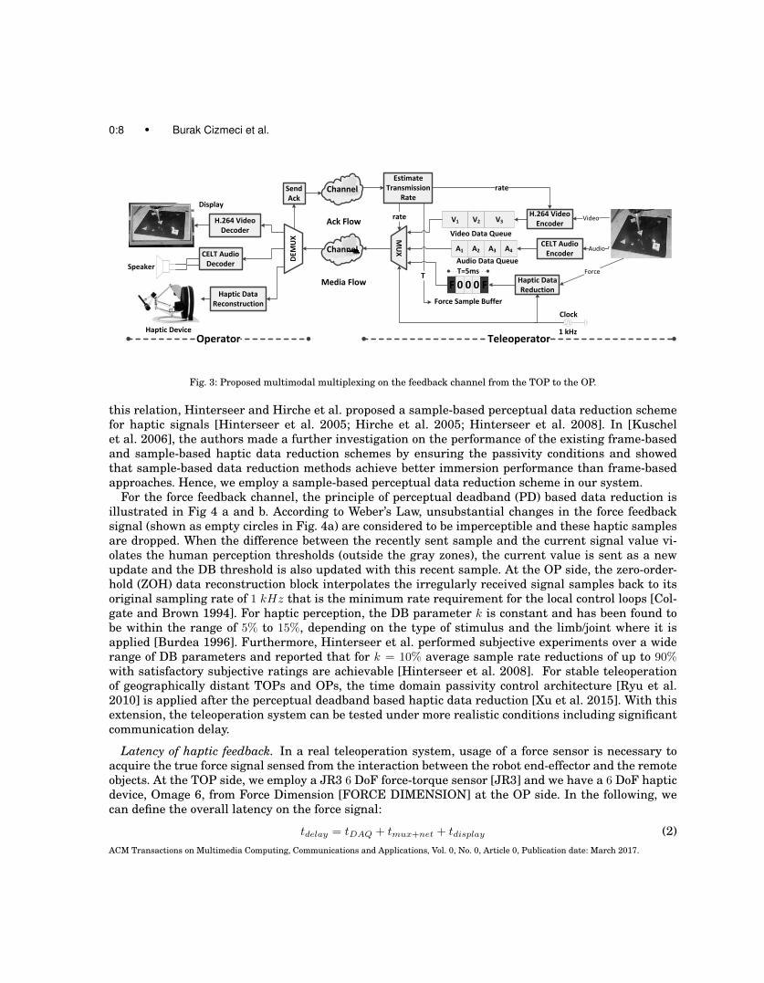
2.5.3 Congestion control. Sudden congestion events are considered as unexpected transmissionrate drops due to increased side traffic in the network which may have dangerous effects during te-lemanipulation. When congestion happens, the system enters an uncertain state for which the trans-mission rate is assumed to be unknown. Consequently, until transmission rate estimation convergesto the current bitrate of the link, the current system parameters stay ambiguous and the signal delayssuddenly increase at the same time. A trivial solution to the problem would be to stop immediatelyand restart the system from the lowest possible bitrate parameters. However, the transition wouldinterrupt the user’s interaction and it would take time to converge to a reliable transmission rateestimate. Also, if the congestions happen frequently, the stop and adaptation states can be annoyingto the OP. Concerning a smooth transition to the new network conditions, an intelligent video framedropping and bitrate adaptation strategy is applied. In Algorithm 4, we give our proposed method forcongestion control for the transmission rate estimation in Algorithm 2. In line 1, the derivative of theestimated transmission rate is computed using a 4th order FIR filter. An increasing positive deriva-tive of the transmission rate indicates a congestion event with a sudden drop. A decreasing negativederivative relates to an increasing transmission rate. Congestion control is activated when either thedelay constraint for the force samples or the video frames is violated (Line 2 in Algorithm 4) and thederivative of the transmission rate is higher than a threshold. When the congestion starts, the currentvideo transmission buffer is discarded and the video transmission breaks until all unacknowledgedframes are acknowledged (Lines 3-6 in Algorithm 4). Then the system continues probing the availabletransmission rate by restarting the video transmission with half the frame rate (temporal scalability)and intra only mode. With this approach, we can safely sample the transmission rate, and the inter-ruptions of the video caused by the cleared buffers are quickly recovered with intra frames (Lines 7-12in Algorithm 4). When the delay constraints are back to normal and TRderivative reaches a value lo-
ACM Transactions on Multimedia Computing, Communications and Applications, Vol. 0, No. 0, Article 0, Publication date: March 2017.
0:16 • Burak Cizmeci et al.
ALGORITHM 4: Congestion control algorithm1 TRderivative(i) = ((TRest(i− 3)− TRest(i)) + 2 ∗ (TRest(i− 2)− TRest(i− 1)))/8;2 if TRderivative(i) >= Thr&&(ForceDelay > ForceDelayConst||V ideoDelay > V ideoDelayConst) then3 if UnackedV ideoNumber > 0&&SignalStop == true then4 EmptyV ideoBuffer();5 V ideoTransF lag = false;6 end7 else8 FPSscale = 2;9 V ideoMode = IntraOnly;
10 V ideoTransF lag = true;11 SignalStop = false;12 end13 end14 else15 if WaitingT ime > WaitThr then16 FPSscale = 1;17 V ideoMode = InterIntra;18 SignalStop = true;19 end20 end
wer than the threshold, the system enters the recovery state and keeps its low rate state (Lines 8-9)until a wait time threshold is reached (Line 15). Thereupon, the system increases the video framerateback to normal and switches back to inter-intra coding mode (Lines 16-18).
3. EXPERIMENTAL SETUP AND RESULTS
The multiplexing scheme is evaluated using a teleoperation system consisting of a KUKA Light WeightRobot arm [KUKA], a JR3 Force/Torque sensor [JR3] and a Force Dimension Omega 6 haptic device[FORCE DIMENSION]. The TOP and OP are separated by a hardware network emulator [APPOSITE-TECH] which can impose precise channel rate limitations and network delay. The tested RTT delaysare symmetrically set in the network emulator and the feedback channel that transmits the velocityand acknowledgment packets is assumed to have enough transmission rate in our experiments. Real-time Xenomai Linux-based machines are used to measure signal latencies and estimate the transmis-sion rate. The GigE camera [MAKO G-223] is attached to the robotic arm (eye-on-the hand) focusingon the operating end-effector and its operation region. The TOP robot is equipped with a single-pointcontact tool to interact with wooden toys in the remote environment. Using the tool, the OP can movethe toys and peg them in the corresponding holes, which can be considered as a representative task forteleoperation applications. Appendix B gives detailed information about the design of the teleoperationtestbed and the experimental procedure.
3.1 Experiment 1: Teleoperation over constant bitrate (CBR) links
In this experiment, we demonstrate the performance of the system for CBR links. The CBR link fromTOP to OP is set to 1, 2 and 3 Mbps with a symmetric RTT delay of 100 ms. The OP performs thefollowing fixed task: OP moves the tool tip, holds the object from the hole, moves it 10 cm, releasesand moves it back to the initial position (see Appendix B for details). The target points are marked toavoid the deviation from the desired manipulation. During the teleoperation, the estimated transmis-sion rate, the number of transmitted packets, PSNR for visual quality and signal delays are instantlyprobed for the evaluation of the teleoperation system together with the multiplexing scheme.ACM Transactions on Multimedia Computing, Communications and Applications, Vol. 0, No. 0, Article 0, Publication date: March 2017.

A Multiplexing Scheme for Multimodal Teleoperation • 0:17
TRest performance: In Table I, we observe that the mean of the transmission rate estimate conver-ges to the target bitrate. Approximately 97 − 99% of the available transmission rate can be detected.In the latter columns, we report the root mean squared error (TRrmseest ) and standard deviation (TRσest)from the original transmission rate as the precision loss of the transmission rate estimation. We ob-serve a little precision loss in the estimate as the transmission rate increases because of the numericalcomputation error issues mentioned in Section 2.5.1.Packet rate: As the available transmission rate increases, the average packet rate rises due to theincreased video bitrate for better visual quality. The packet rate results are very promising compa-red to haptic communication systems without data reduction schemes, which need to transmit 1000packets/sec. With the help of haptic data reduction and multiplexing scheme, it is still possible to havea packet rate reduction around 75 − 87% for audio, video and haptics if we take 1000 packets/sec asreference. If we compare this result with the systems which are transmitting only haptic signals witha data reduction of 90% [Hinterseer et al. 2008], we can conclude that the multiplexed audio and videodata doesn’t cause a high increase in packet rate.Visual quality PSNR: The visual quality of the teleoperation scenes (1280 × 720 @ 25 fps) are mea-sured in terms of mean, standard deviation, minimum and maximum of PSNR in dB. We observe thatthe system adapts the video bitrate, and the quality of the video stream is improved as the availabletransmission rate increases. It is important to note that the quality of the video is highly dependenton the motion in the teleoperation scenes. Because of the camera mounted on the robotic arm, whenthe robot is in high motion, the PSNR reaches to its minimum value. Conversely, the PSNR reaches itsmaximum value when the robot is steady.Force delay: The statistics of force delay demonstrate that the multiplexing scheme successfully con-trols the delay of the force signal. In the lower part of Table I, the maximum force delay column showsthat the force samples are not delayed more than the multiplexing buffer size which is determined byAlgorithm 3. The mean and jitter values refer to the average and standard deviation of the originaltransmission delay for the force samples. To avoid signal distortion for the early force sample arrivals,the demultiplexer applies play-out buffering by checking the timestamps to display the force sampleat the correct time. Hence, the mean force delay can be shifted to the target delay with 0 ms jitter.Video delay: We observe that the linear video bitrate model determined in Section 2.5.2 performssuccessfully in controlling the video delay together with the single-frame delay constraint. The delayconstraint is set to 35 ms and we observe that the system converges to the constraint with very low jit-ter. If we check the minimum and maximum delays, there exist sometimes outliers due to rate control
Table I. : The transmission rate estimation performance for CBR links, packet rate of the system and visual quality of theteleoperation scenes are illustrated. Additionally, we present the delay performance of the system with respect to each signal.The one-way 50 ms delay is subtracted from the results to clearly illustrate the delay effect of the transmission bottleneck.
TR (kbps) TRest performance Packet rate Visual quality PSNRTRmeanest
(kbps)
TRσest(kbps)
TRrmseest
(kbps)
mean
(packets/sec)
stddev
(packets/sec)
mean
(dB)
stddev
(dB)
min
(dB)
max
(dB)
1000 989.25 2.83 11.11 139.68 6.76 32.40 3.43 28.87 40.82
2000 1964.55 4.10 35.68 192.26 4.11 37.63 3.22 30.44 42.39
3000 2938.22 9.17 62.45 251.09 7.82 40.12 2.84 33.26 43.33
TR (kbps) Force delay (ms) Video delay (ms) Audio delay (ms)mean jitter min max mean jitter min max mean jitter min max
1000 10.14 5.18 1 15 31.35 1.65 23.3 52.70 12.27 5.64 2.00 29.00
2000 6.47 2.88 1 10 33.05 1.13 31.40 50.50 9.89 3.57 1.60 20.20
3000 3.81 1.06 1 5 33.82 1.52 31.40 46.60 8.17 2.10 1.40 13.30
ACM Transactions on Multimedia Computing, Communications and Applications, Vol. 0, No. 0, Article 0, Publication date: March 2017.
0:18 • Burak Cizmeci et al.
deviation on some frames. However, the low jitter value indicates that these outliers very rarely occur.Audio delay: The audio frames reach the demultiplexer side very fast. We observe a little decreasingtrend on the audio delay as the network capacity increases because the audio bitrate is kept constantin all transmission rate conditions as 64 kbps which gives sufficient sound quality for the interaction.Hence, the audio delay slightly decreases as the available transmission rate increases.
3.2 Experiment 2: Congestion control results
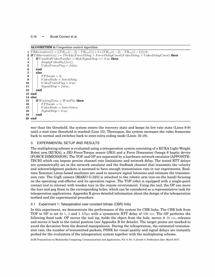
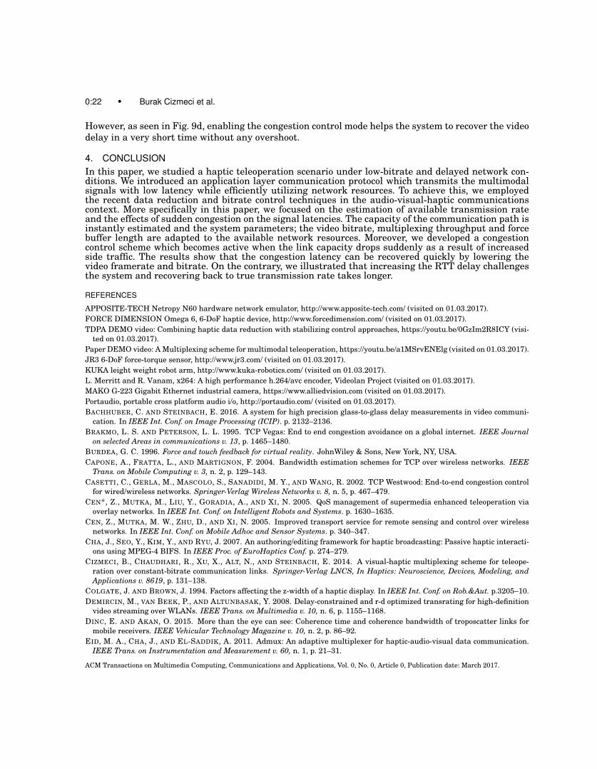
In this experiment, the available transmission rate of the communication link suddenly drops from3 to 2 Mbps while the OP is in contact with a remote object and drags it over the surface. We testthe performance of Algorithm 4 where the system detects congestion and converges quickly back tothe current transmission rate. As the RTT increases, the transmission rate estimation is delayed.Consequently, the system adaptation to the transmission rate change is also delayed. Thus, the systempushes at a high data rate until it estimates the current transmission rate. During this period, signaldelays are higher than the desired delay constraints. In Table II, we show the system response tothe congestion event when the RTT is 100, 200 and 300 ms and compare the signal delays for theenabled and disabled congestion control (Algorithm 4). We show the peak delay for the haptic andvideo signals, compute the transmission rate estimation drop with respect to the target bitrate of 2Mbps and measure convergence time, which is the time difference between the time when congestionbegins and the time when the estimate converges to 2 Mbps. From the table, we can see that thecongestion control reduces the system latency by controlling the video throughput of the system. Onthe other hand, we see that the RTT plays an important role and it gets challenging for the system toadapt the parameters as the RTT increases. In Figures 7, 8 and 9, we illustrate the corresponding forceand video delay plots for the test conditions RTT 100, 200 and 300 ms. In the following, we comment onthe results for the delay plots. The demo video of the setup and the results for RTT = 100 ms can bewatched in the referenced link [Paper DEMO video].RTT 100 ms: Fig. 7 shows the estimated transmission rate results and the delay profiles of video andforce signals when the RTT delay is set to 100 ms. If the congestion control is not enabled, we observethat the transmission rate estimation Algorithm 2 conservatively drops the throughput below 1 Mbpsalthough the current transmission rate is 2 Mbps. However, with the help of Algorithm 4, the systemdetects the congestion event and probes the communication link capacity slightly to converge to thetrue transmission rate. The red line in the figures illustrates the estimated transmission rate andwe observe that the congestion control mode helps the estimator to quickly converge to the currenttransmission rate of the link. Moreover, we draw plots for the force and video delay profiles which arealigned with the transmission rate estimation result. We observe more delay constraint violations ifthe congestion control mode is off. On the other hand, the peak delays do not cause critical lags on bothvideo and force signals as already shown in Table II.RTT 200 ms: Fig. 8 illustrates the estimated transmission rate results and the delay profiles of videoand force signals when the RTT delay is set to 200 ms. If we compare the transmission rate estimation
Table II. : Congestion control results when the link capacity suddenly drops from 3 to 2 Mbps.
RTT (ms) without congestion control with congestion controlDmaxHaptic
(ms)
DmaxV ideo(ms)
TRdrop(kbps)
Tconv(ms)
DmaxHaptic
(ms)
DmaxV ideo(ms)
TRdrop(kbps)
Tconv(ms)
100 49 83 1203 9921 36 60 0 1649
200 59 182 1481 10178 43 79 476 6266
300 85 845 1590 12962 59 100 903 7467
ACM Transactions on Multimedia Computing, Communications and Applications, Vol. 0, No. 0, Article 0, Publication date: March 2017.

A Multiplexing Scheme for Multimodal Teleoperation • 0:19
(a) Force delay without congestion control (b) Force delay with congestion control
(c) Video delay without congestion control (d) Video delay with congestion control
Fig. 7: Delay improvements for congestion control when a sudden transmission rate drop occurs from 3 Mbps to 2 Mbps at aRTT of 100 ms. To illustrate the delays due to the transmission rate, 50 ms one-way delay is subtracted from the signal delays.
results in Fig. 8 with Fig. 7, we observe that the transmission rate estimation diverges very quicklyfrom the current transmission rate as the RTT delay increases from 100 to 200 ms. On the other hand,the congestion control mode helps the estimator to converge to the current transmission rate 2 Mbpsby keeping the turning point above 1.5 Mbps. When we compare the force delay plots Fig. 8a andFig. 8b, the congestion compensation mode quickly keeps the force delay below the desired constraint.However, as we observe in Fig. 8a, the force delay constraint is violated approximately 5 seconds if the
ACM Transactions on Multimedia Computing, Communications and Applications, Vol. 0, No. 0, Article 0, Publication date: March 2017.

0:20 • Burak Cizmeci et al.
(a) Force delay without congestion control (b) Force delay with congestion control
(c) Video delay without congestion control (d) Video delay with congestion control
Fig. 8: Delay improvements for congestion control when a sudden transmission rate drop occurs from 3 Mbps to 2 Mbps at aRTT of 200 ms. To illustrate the delays due to the transmission rate, 100 ms one-way delay is subtracted from the signal delays.
congestion control scheme is switched off. When we compare the video delay profiles in Fig. 8c andFig. 8d, there is a significant improvement on video delay by enabling the congestion detection andcompensation scheme.RTT 300 ms: Fig. 9 illustrates the estimated transmission rate results and the delay profiles forvideo and force signals when the RTT delay is set to 300 ms. When we compare the transmission rateestimation results in Fig. 9 with Figs. 8 and 7, the increasing RTT delay significantly impairs theACM Transactions on Multimedia Computing, Communications and Applications, Vol. 0, No. 0, Article 0, Publication date: March 2017.

A Multiplexing Scheme for Multimodal Teleoperation • 0:21
(a) Force delay without congestion control (b) Force delay with congestion control
(c) Video delay without congestion control (d) Video delay with congestion control
Fig. 9: Delay improvements for congestion control when a sudden transmission rate drop occurs from 3 Mbps to 2 Mbps at aRTT of 300 ms. To illustrate the delays due to the transmission rate, 150 ms one-way delay is subtracted from the signal delays.
estimation. Especially if the congestion control scheme is off, the estimation drops close to 500 kbps andit takes more than 10 seconds to converge to the current transmission rate of the link. Similar to theforce delay results for RTT delay 100 ms case, the congestion control mode quickly recovers the forcedelay back to its desired constraint. On the other hand, when the congestion control mode is switchedoff, the video delay diverges close to 900 ms because of the late adaptation of video bitrate in Fig. 9c.
ACM Transactions on Multimedia Computing, Communications and Applications, Vol. 0, No. 0, Article 0, Publication date: March 2017.
0:22 • Burak Cizmeci et al.
However, as seen in Fig. 9d, enabling the congestion control mode helps the system to recover the videodelay in a very short time without any overshoot.
4. CONCLUSIONIn this paper, we studied a haptic teleoperation scenario under low-bitrate and delayed network con-ditions. We introduced an application layer communication protocol which transmits the multimodalsignals with low latency while efficiently utilizing network resources. To achieve this, we employedthe recent data reduction and bitrate control techniques in the audio-visual-haptic communicationscontext. More specifically in this paper, we focused on the estimation of available transmission rateand the effects of sudden congestion on the signal latencies. The capacity of the communication path isinstantly estimated and the system parameters; the video bitrate, multiplexing throughput and forcebuffer length are adapted to the available network resources. Moreover, we developed a congestioncontrol scheme which becomes active when the link capacity drops suddenly as a result of increasedside traffic. The results show that the congestion latency can be recovered quickly by lowering thevideo framerate and bitrate. On the contrary, we illustrated that increasing the RTT delay challengesthe system and recovering back to true transmission rate takes longer.
REFERENCES
APPOSITE-TECH Netropy N60 hardware network emulator, http://www.apposite-tech.com/ (visited on 01.03.2017).FORCE DIMENSION Omega 6, 6-DoF haptic device, http://www.forcedimension.com/ (visited on 01.03.2017).TDPA DEMO video: Combining haptic data reduction with stabilizing control approaches, https://youtu.be/0GzIm2R8ICY (visi-
ted on 01.03.2017).Paper DEMO video: A Multiplexing scheme for multimodal teleoperation, https://youtu.be/a1MSrvENElg (visited on 01.03.2017).JR3 6-DoF force-torque sensor, http://www.jr3.com/ (visited on 01.03.2017).KUKA leight weight robot arm, http://www.kuka-robotics.com/ (visited on 01.03.2017).L. Merritt and R. Vanam, x264: A high performance h.264/avc encoder, Videolan Project (visited on 01.03.2017).MAKO G-223 Gigabit Ethernet industrial camera, https://www.alliedvision.com (visited on 01.03.2017).Portaudio, portable cross platform audio i/o, http://portaudio.com/ (visited on 01.03.2017).BACHHUBER, C. AND STEINBACH, E. 2016. A system for high precision glass-to-glass delay measurements in video communi-
cation. In IEEE Int. Conf. on Image Processing (ICIP). p. 2132–2136.BRAKMO, L. S. AND PETERSON, L. L. 1995. TCP Vegas: End to end congestion avoidance on a global internet. IEEE Journal
on selected Areas in communications v. 13, p. 1465–1480.BURDEA, G. C. 1996. Force and touch feedback for virtual reality. JohnWiley & Sons, New York, NY, USA.CAPONE, A., FRATTA, L., AND MARTIGNON, F. 2004. Bandwidth estimation schemes for TCP over wireless networks. IEEE
Trans. on Mobile Computing v. 3, n. 2, p. 129–143.CASETTI, C., GERLA, M., MASCOLO, S., SANADIDI, M. Y., AND WANG, R. 2002. TCP Westwood: End-to-end congestion control
for wired/wireless networks. Springer-Verlag Wireless Networks v. 8, n. 5, p. 467–479.CEN*, Z., MUTKA, M., LIU, Y., GORADIA, A., AND XI, N. 2005. QoS management of supermedia enhanced teleoperation via
overlay networks. In IEEE Int. Conf. on Intelligent Robots and Systems. p. 1630–1635.CEN, Z., MUTKA, M. W., ZHU, D., AND XI, N. 2005. Improved transport service for remote sensing and control over wireless
networks. In IEEE Int. Conf. on Mobile Adhoc and Sensor Systems. p. 340–347.CHA, J., SEO, Y., KIM, Y., AND RYU, J. 2007. An authoring/editing framework for haptic broadcasting: Passive haptic interacti-
ons using MPEG-4 BIFS. In IEEE Proc. of EuroHaptics Conf. p. 274–279.CIZMECI, B., CHAUDHARI, R., XU, X., ALT, N., AND STEINBACH, E. 2014. A visual-haptic multiplexing scheme for teleope-
ration over constant-bitrate communication links. Springer-Verlag LNCS, In Haptics: Neuroscience, Devices, Modeling, andApplications v. 8619, p. 131–138.
COLGATE, J. AND BROWN, J. 1994. Factors affecting the z-width of a haptic display. In IEEE Int. Conf. on Rob.&Aut. p.3205–10.DEMIRCIN, M., VAN BEEK, P., AND ALTUNBASAK, Y. 2008. Delay-constrained and r-d optimized transrating for high-definition
video streaming over WLANs. IEEE Trans. on Multimedia v. 10, n. 6, p. 1155–1168.DINC, E. AND AKAN, O. 2015. More than the eye can see: Coherence time and coherence bandwidth of troposcatter links for
mobile receivers. IEEE Vehicular Technology Magazine v. 10, n. 2, p. 86–92.EID, M. A., CHA, J., AND EL-SADDIK, A. 2011. Admux: An adaptive multiplexer for haptic-audio-visual data communication.
IEEE Trans. on Instrumentation and Measurement v. 60, n. 1, p. 21–31.
ACM Transactions on Multimedia Computing, Communications and Applications, Vol. 0, No. 0, Article 0, Publication date: March 2017.

A Multiplexing Scheme for Multimodal Teleoperation • 0:23
FERRELL, W. R. 1965. Remote manipulation with transmission delay. IEEE Trans. on Hum. Fact. in Elec. v. 6, n. 1, p. 24–32.GAO, M., CIZMECI, B., EILER, M., STEINBACH, E., ZHAO, D., AND GAO, W. 2015. Macroblock level rate control for low delay
H.264/AVC based video communication. In IEEE Picture Coding Symposium. p. 210–215.GOELLER, M., OBERLAENDER, J., UHL, K., ROENNAU, A., AND DILLMANN, R. 2012. Modular robots for on-orbit satellite
servicing. In IEEE Int. Conf. on Robotics and Biomimetics (ROBIO). p. 2018–2023.HE, Z. AND MITRA, S. 2002. Optimum bit allocation and accurate rate control for video coding via ρ-domain source modeling.
IEEE Trans. on Circuits and Systems for Video Technology v. 12, n. 10, p. 840–849.HINTERSEER, P., HIRCHE, S., CHAUDHURI, S., STEINBACH, E., AND BUSS, M. 2008. Perception-based data reduction and
transmission of haptic data in telepresence and teleaction systems. IEEE Trans. on Signal Processing v. 56, n. 2, p. 588–597.HINTERSEER, P., STEINBACH, E., HIRCHE, S., AND BUSS, M. 2005. A novel psychophysically motivated transmission approach
for haptic data streams in telepresence and teleaction systems. In IEEE Int. Conf. on Acous., Sp., and Sig. Proc. p. 1097–1100.HIRCHE, S., HINTERSEER, P., STEINBACH, E., AND BUSS, M. 2005. Network traffic reduction in haptic telepresence systems
by deadband control. In 16th IFAC World Congress. p. 77–82.ISOMURA, E., TASAKA, S., AND NUNOME, T. 2011. QoE enhancement in audiovisual and haptic interactive ip communications
by media adaptive intra-stream synchronization. In TENCON 2011 - IEEE Region 10 Conf. p. 1085–1089.ITU-T. 1993. ITU-T JPEG Standard, digital compression and coding of continuous-tone still images.ITU-T. 2005. ITU-T H.264, advanced video coding for generic audiovisual services.KAEDE, S., NUNOME, T., AND TASAKA, S. 2015. QoE enhancement of audiovisual and haptic interactive IP communications by
user-assistance. In IEEE 18th Int. Conf. on Computational Science and Engineering. p. 35–42.KUSCHEL, M., KREMER, P., HIRCHE, S., AND BUSS, M. 2006. Lossy data reduction methods for haptic telepresence systems.
In Proc. IEEE Int. Conf. on Rob. & Aut. p. 2933–2938.LEE, S., MOON, S., AND KIM, J. 2006. A network-adaptive transport scheme for haptic-based collaborative virtual environ-
ments. In Proc. of 5th ACM SIGCOMM Workshop on Network and System Support for Games, article no. 13.MARSHALL, A., YAP, K. M., AND YU, W. 2008. Providing QoS for networked peers in distributed haptic virtual environments.
Hindawi, Journal of Advances in Multimedia v. 2008, n. 841590.OSMAN, H. A., EID, M., IGLESIAS, R., AND SADDIK, A. E. 2007. ALPHAN: Application Layer Protocol for HAptic Networking.
In IEEE Int. Workshop on Haptic, Audio and Visual Environments and Games. p. 96–101.PING, L., WENJUAN, L., AND ZENGQI, S. 2005. Transport layer protocol reconfiguration for network-based robot control system.
In IEEE Proc. of Networking, Sensing and Control. p. 1049–1053.PYKE, J., HART, M., POPOV, V., HARRIS, R., AND MCGRATH, S. 2007. A tele-ultrasound system for real-time medical imaging
in resource-limited settings. In IEEE Int. Conf. of Eng. in Medicine and Biology Society. p. 3094–3097.RANK, M., SHI, Z., MLLER, H., AND HIRCHE, S. 2010. Perception of delay in haptic telepresence systems. MIT Presence v.
19, n. 5, p. 389–399.RYU, J.-H., ARTIGAS, J., AND PREUSCHE, C. 2010. A passive bilateral control scheme for a teleoperator with time-varying
communication delay. Mechatronics v. 20, n. 7, p. 812–823.SHERIDAN, T. 1993. Space teleoperation through time delay: review and prognosis. IEEE Trans. on Robotics and Automa-
tion v.9, n.5, p.592–606.SILVA, J. M., OROZCO, M., CHA, J., SADDIK, A. E., AND PETRIU, E. M. 2013. Human perception of haptic-to-video and haptic-
to-audio skew in multimedia applications. ACM Trans. on Multimedia Comp., Comm. and App. (TOMM) v. 9, n. 2, p. 9:1–9:16.STEINBACH, E., HIRCHE, S., KAMMERL, J., VITTORIAS, I., AND CHAUDHARI, R. 2011. Haptic data compression and commu-
nication for telepresence and teleaction. IEEE Signal Processing Magazine v. 28, n. 1, p. 87–96.STOICA, I., SHENKER, S., AND ZHANG, H. 1998. Core-stateless fair queueing: Achieving approximately fair bandwidth alloca-
tions in high speed networks. ACM SIGCOMM Comput. Comm. Rev. v. 28, n. 4, p. 118–130.UCHIMURA, Y., OHNISHI, K., AND YAKOH, T. 2002. Bilateral robot system on the real time network structure. In IEEE Int.
Workshop on Advanced Motion Control. p. 63–68.VALIN, J., TERRIBERRY, T., MONTGOMERY, C., AND MAXWELL, G. 2010. A high-quality speech and audio codec with less than
10-ms delay. IEEE Trans. on Audio, Speech, and Language Processing v. 18, n. 1, p. 58–67.VOGELS, I. 2004. Detection of temporal delays in visual-haptic interfaces. HUMAN FACTORS v. 46, n. 1, p. 118–134.WALRAEVENS, J. 2005. Discrete-time queueing models with priorities. Ph.D. Dissertation, (TELIN) Ghent University.WEBER, E. 1851. Die lehre vom tastsinn und gemeingefuehl, auf versuche gegruendet.XU, X., CIZMECI, B., SCHUWERK, C., AND STEINBACH, E. 2015. Haptic data reduction for time-delayed teleoperation using
the time domain passivity approach. In IEEE World Haptics Conf. (WHC). p. 512–518.
ACM Transactions on Multimedia Computing, Communications and Applications, Vol. 0, No. 0, Article 0, Publication date: March 2017.

0:24 • Burak Cizmeci et al.
YAMAMOTO, S., YASHIRO, D., YUBAI, K., AND KOMADA, S. 2014. Rate control based on queuing state observer for visual-hapticcommunication. In IEEE Int. Workshop on Advanced Motion Control. p. 569–574.
YASHIRO, D., TIAN, D., AND YAKOH, T. 2013. End-to-end flow control for visual-haptic communication in the presence ofbandwidth change. Wiley Electronics and Communications in Japan v. 96, n. 11, p. 26–34.
ZHANG, F. AND STEINBACH, E. 2011. Improved ρ-domain rate control with accurate header size estimation. In IEEE Int. Conf.on Acous., Speech and Signal Proc. p. 813–816.
ACM Transactions on Multimedia Computing, Communications and Applications, Vol. 0, No. 0, Article 0, Publication date: March 2017.

A Multiplexing Scheme for Multimodal Teleoperation • 0:25
Fig. 10: MUX Header (1 byte) Structure in bits.
A. MULTIPLEXING HEADER STRUCTURE
In Fig. 10 we show the structure of “MUX Header”. The first 3 bits marked with “M” in Fig. 10 repre-sent the packet type. With 3 bits, 8 different packet types can be signalled which is sufficient for thecurrent multiplexing scheme. Currently, bits 3, 4, 5 and 6 (“N”) are reserved for future modalities andcontrol signalling. If the packet type includes video data, the bit 7 tagged as “L” is used to signal thevideo frame completion which means the frame is ready for decoding. The multiplexing scheme dividesthe encoded video stream into fragments of different sizes. When the current video frame transmissionis completed, the demultiplexer is triggered to pass the bitstream to the video decoder. In Table III, themultiplexing header is shown as H(1) where (1) represents the size of the information as 1 byte. Accor-ding to the packet type, we need to signal additional information like time-stamps, data indexes andpayload lengths after the multiplexing header. Every packet contains a time-stamp shown as PTS(2)which is the clock time when the packet is pushed into the channel. Using the packet time-stamp, thedemultiplexer can measure the transmission time of each packet. The multimedia information followsthese headers and according to the type of the modality, the following information is added:Force: If the packet contains a force sample, sample id SID(2), sample time-stamp STS(2), samplepayload SPL(6) and energy payload EPL(12) which is used for the control architecture are added tothe packet. Each force sample is represented by a 2 bytes floating number in the sample payload andeach energy sample is represented by a 4 bytes floating number in the energy payload.Video: If the packet contains a video frame fragment, the corresponding frame number FN(2), frag-ment number FGN(2), frame time-stamp FTS(2) and video payload length V PLL(2) are written intothe packet. The payload size (Y bytes) of the fragment is written into V PLL(2). After the multiplexinginformation, the payload data is written and it occupies Y bytes which is decided by the multiplexingalgorithm.Audio: Unlike video frames, many audio frames can fit into one packet due to their small frame size.First, we indicate the number of audio frames NAF (1) = a and then we write the time-stamp ATS(2),
Table III. : Packet Structures
Packet type Packet structure Size (bytes)F H(1) − PTS(2) − SID(2) − STS(2) − SPL(6) − EPL(12) 25
A H(1) − PTS(2) −NAF (1) − a · (ATS(2) −AFN(2) −APLL(2)) −APL(X) 4 + a · 6 +X
V H(1) − PTS(2) − FN(2) − FGN(2) − FTS(2) − V PLL(2) − V PL(Y ) 11 + Y
AV H(1)−PTS(2)−NAF (1)−a · (ATS(2)−AFN(2)−APLL(2))−APL(X)−FN(2) − FGN(2) − FTS(2) − V PLL(2) − V PL(Y )
12 + a · 6 +X + Y
AF H(1)−PTS(2)−NAF (1)−a · (ATS(2)−AFN(2)−APLL(2))−APL(X)−STS(2) − SID(2) − SPL(6) − EPL(12)
26 + a · 6 +X
VF H(1)−PTS(2)−SID(2)−STS(2)−SPL(6)−EPL(12)−FN(2)−FGN(2)−FTS(2) − V PLL(2) − V PL(Y )
33 + Y
AVF H(1)−PTS(2)−NAF (1)−a · (ATS(2)−AFN(2)−APLL(2))−APL(X)−FN(2) − FGN(2) − FTS(2) − V PLL(2) − V PL(Y ) − SID(2) − STS(2) −SPL(6) − EPL(12)
34 + a · 6 +X + Y
ACM Transactions on Multimedia Computing, Communications and Applications, Vol. 0, No. 0, Article 0, Publication date: March 2017.

0:26 • Burak Cizmeci et al.
frame number AFN(2) and payload length APLL(2) for each audio frame. After all the side informa-tion, the audio payloads (in total X bytes, determined by the multiplexer) are written into the packet.In addition to the multiplexing information, the transport protocol adds its own header informationto every packet. The used protocol(s) should be known to the multiplexer because the protocol headersize needs to be taken into account while allocating the channel rate to the packets. In our set-up, theUDP/IPv4 protocol is used and 42 bytes are reserved for the UDP/IPv4 header information. The overalloverhead size is calculated by adding up the 42 bytes UDP/IPv4 protocol header to the estimated sizeof each packet type given in Table III.
B. TELEOPERATION TESTBED DESIGN
Fig. 11 illustrates the implemented testbed. The OP and TOP computers, running Real-Time (RT)Xenomai Linux kernel, run the local control loops at 1 kHz and are physically separated via ethernetwith a hardware network emulator (Apposite Netropy N60). The TOP computer communicates withthe KUKA LWR control unit and transmits the computed (X,Y, Z) position of the robot end-effector.The KUKA control unit has its own closed kinematics computation loop for moving the robot joints tothe desired end-effector position. The video encoding and decoding are performed on separate machinesbecause the computation load of the video processing interferes with the local control loops at the OPand TOP. It is challenging to synchronize the control loops at 1 ms accuracy. Therefore, we employ aseparate computer as a clock server machine that sends timestamps to synchronize the control loopsat both sides. These timestamps are used to measure the end-to-end latencies for the evaluation of thesystem performance.
The dimensions of the manipulation tool are given in Fig. 12a. Its total length from bottom to tip-end is 165 mm, and the tip diameter is semi-conical from 8.8 to 14 mm to fit into the object holes (13mm, given in Fig. 12c) for manipulation tasks involving holding and dragging. Fig. 12b illustrates the
Operator TeleoperatorNetworkEmulator
ClockMachine
Apposite Netropy N60
RT Linux
VideoEncoder
x264
VideoDecoderffmpeg
RT Linux RT LinuxFPGA
Linux Linux
KUKA LWR Control Unit
VxWorks
Fig. 11: Teleoperation system testbed: The physical structure of the teleoperation system is given, and the computers andhardware are interconnected through ethernet-based interfaces.
ACM Transactions on Multimedia Computing, Communications and Applications, Vol. 0, No. 0, Article 0, Publication date: March 2017.

A Multiplexing Scheme for Multimodal Teleoperation • 0:27
(a) Single-point metalend-effector, dimensionsin mm
350 mm
35
0 m
m
50 mm
70 mm
65 mm
35 mm
35 mm
50 mm 50 mm
35 mm
h=10 mm
48 mm
48 mm
(b) Manipulation platform dimensions
43 mm 43 mm
43
mm
43 mm
13 mm
13 mm
h=19 mm
(c) Dimensions of the objects for manipulation
Fig. 12: Dimensions for the single-point tool, manipulation platform and objects.
construction of the manipulation platform. As observed from Fig. 12b, the dimensions of the triangle-and square-shaped holes are drilled slightly larger (+5mm) to perform the pegging operation smoothly.The 3D object files are provided at the “Supplemental Files” section. Therefore, the objects and themanipulation tool can be either reproduced in a workshop or 3D printed.
Fig. 13a shows the experimental setup at the TOP side. The camera is mounted and fixed on the robothand (eye-on-the-hand) monitoring the single-point metal end-effector, the manipulation platform andobjects. Fig. 13b illustrates how we performed the experiments 1 and 2. For consistency between diffe-rent experimental sessions and reproducible results, we force the OP to make a controlled movementduring the manipulation. The procedure is as follows:
(1) At the beginning the end-effector is in free-space above the object. The OP slightly moves towardsthe object and gets in contact with it by holding from its hole.
(2) The OP drags the object to the target location which is placed 10 cm apart as shown in Fig. 13b.(3) When the target is achieved, the OP releases the object and moves upwards.(4) The OP approaches to the object once again to drag it back to the initial position.(5) Similarly, it holds the object brings it back to the initial position and releases the object.
ACM Transactions on Multimedia Computing, Communications and Applications, Vol. 0, No. 0, Article 0, Publication date: March 2017.

0:28 • Burak Cizmeci et al.
(a) Teleoperator KUKA LWRarm with single-point metal end-effector performing peg-in-holetask.
(1)Move 10 cm
(2)Bring back
(b) The procedure of experiments 1 and 2
Fig. 13: The teleoperator side manipulation environment
C. DISCUSSION ON DELAY REQUIREMENTS AND INTER-MEDIA SYNCHRONIZATION
In Table IV, we give the latency performance of our teleoperation system excluding the one-way pro-pagation delay. From Table IV, we can conclude that our teleoperation system does not violate thereported maximum tolerable delay and jitter constraints shown as bold numbers [Marshall et al. 2008;Eid et al. 2011]. On the other hand, one-way propagation delay can not impair the delay require-ments for video and audio streams up to 275 ms and 100 ms delays respectively. However, the delayrequirement on haptic signals in Table IV is very tight but this is for systems without delay-robustcontrol architectures. In our system, delays up to 250 ms one-way can be tolerated [Xu et al. 2015]. It isimportant to note that the QoS constraints given in Table IV were determined for teleconferencing sy-stems (audio-video) and shared haptic virtual environments. Therefore, we also need to consider delayperception research for teleoperation systems and cross-modality effects.
Due to the bi-directional communication of velocity/position - force signals and varying environmentconditions, studying the human delay perception in haptic teleoperation systems is challenging compa-red to audio-visual delay perception [Rank et al. 2010]. In [Vogels 2004], the author reported that timedifferences up to 45 ms between visual and force signals are acceptable when the subject hits a stiffwall with the haptic device. Besides, the author reported that the perception of delay between force andvisual stimuli can be larger under some telemanipulation situations. In [Rank et al. 2010], the authorsshowed that the operator’s movement dynamics, the local haptic device features, and the penetration
Table IV. : The provided service without one-way delay and the delay requirements for haptic, video and audio streams. The boldnumbers refer to the delay requirements as the maximum tolerable delay and jitter for haptic, video and audio streams given in[Marshall et al.2008; Eid et al. 2011]
Modality Delay(ms) Jitter(ms)Haptic 38 − 48 < 50 0 < 2Video 125 < 400 3 < 30Audio 50 < 150 10 < 30
ACM Transactions on Multimedia Computing, Communications and Applications, Vol. 0, No. 0, Article 0, Publication date: March 2017.

A Multiplexing Scheme for Multimodal Teleoperation • 0:29
A VH
t (ms)0 38 1255087 ms
(a) with intrinsic delays
A VHt (ms)0 5 3510
30 ms
(b) without intrinsic delay (only multiplex-ing delay)
Fig. 14: The inter-media synchronization
depth into structures of the remote environment play an effect on the visual-haptic delay perception.In their experiments, the delay detection thresholds are between 24 to 46 ms. Unlike the other publi-cations, the authors in [Silva et al. 2013] report that the acceptable delay between all modalities (A-V,A-H and V-H) is around 100 ms regardless of the haptic device type. In contrast to previous studies,they performed the experiments in a passive interaction where the subject just holds the stylus andperceives a controlled interaction. To sum up, it is important to note that most of these previous studiesdidn’t consider the intrinsic delays in their system as we reported in this paper. In Fig. 14, we give themaximum time difference (which takes place when force buffer size is 5 ms) between modalities whenwe consider the delays including (Fig. 14a) and excluding (Fig. 14b) the intrinsic and encoding delays.As seen in Fig. 14a, the delay between video and haptic signals is around 87 ms. Under the currentconditions, subjects report that they perceive the signals still in synchrony and the remote interactionis smooth for all tested RTT delay cases. On the other hand, it is important to note that the intrinsicdelays and encoding time can be reduced by using a specialized hardware at the visual communicati-ons part of the system. If these delays are reduced, the asynchrony between the signals is lower thanthe reported thresholds in the literature given above (see Fig. 14b with the multiplexing delays only).
ACM Transactions on Multimedia Computing, Communications and Applications, Vol. 0, No. 0, Article 0, Publication date: March 2017.