A Multi-Vdd Dynamic Variable-Pipeline On-Chip Router for CMPs Hiroki Matsutani Yuto Hirata Michihiro...
33
A Multi-Vdd Dynamic Variable-Pipeline On-Chip Router for CMPs Hiroki Matsutani Yuto Hirata Michihiro Koibuchi Kimiyoshi Usami Hiroshi Nakamura Hideharu Amano (Keio Univ, Japan) (Keio Univ, Japan) (NII, Japan) (Shibaura IT, Japan) (Univ Tokyo,
-
Upload
raymond-robbins -
Category
Documents
-
view
219 -
download
0
Transcript of A Multi-Vdd Dynamic Variable-Pipeline On-Chip Router for CMPs Hiroki Matsutani Yuto Hirata Michihiro...

A Multi-Vdd Dynamic Variable-Pipeline On-Chip
Router for CMPs
Hiroki MatsutaniYuto HirataMichihiro KoibuchiKimiyoshi UsamiHiroshi Nakamura Hideharu Amano
(Keio Univ, Japan)(Keio Univ, Japan)
(NII, Japan)(Shibaura IT, Japan)(Univ Tokyo, Japan)
(Keio Univ, Japan)

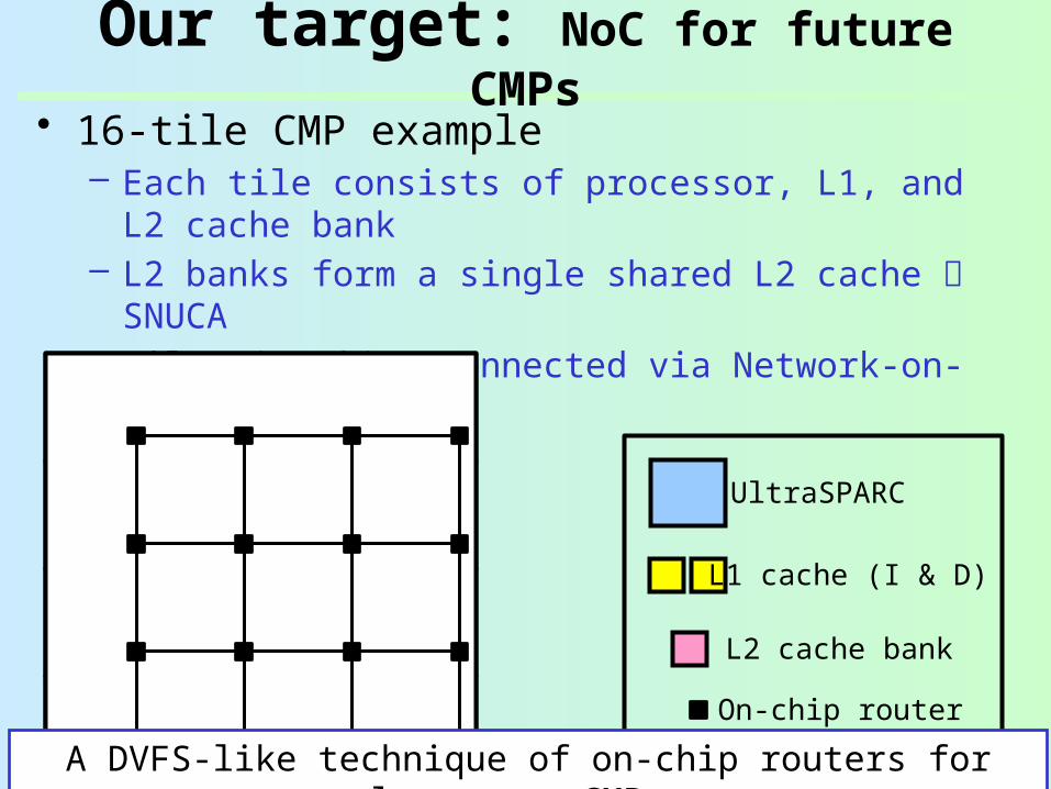
Our target: NoC for future CMPs• 16-tile CMP example
– Each tile consists of processor, L1, and L2 cache bank
– L2 banks form a single shared L2 cache SNUCA
UltraSPARC
L1 cache (I & D)
L2 cache bank
Our target: NoC for future CMPs• 16-tile CMP example
– Each tile consists of processor, L1, and L2 cache bank
– L2 banks form a single shared L2 cache SNUCA– Tiles are interconnected via Network-on-Chip
(NoC)
On-chip router
UltraSPARC
L1 cache (I & D)
L2 cache bank
A DVFS-like technique of on-chip routers for low-power CMPs

Problem: DVFS for on-chip routers
• If DVFS is applied to on-chip routers…– Each router works at different frequency– How to communicate between different frequency
domains?
333MHz 400MHz

• If DVFS is applied to on-chip routers…– Each router works at different frequency– How to communicate between different frequency
domains?
1. Frequency of a router is restricted to integer multiple of adjacent one– E.g., 300MHz vs.
150MHz
2. Asynchronous communication protocol– Versatile but too costly
333MHz 400MHz Possible solutions
Any other solution? – Multi-Vdd variable-pipeline router !
Problem: DVFS for on-chip routers
Multi-Vdd variable-pipeline router
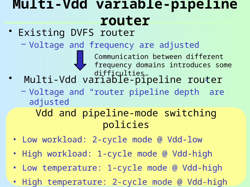
• Existing DVFS router– Voltage and frequency are adjusted
• Multi-Vdd variable-pipeline router– Voltage and “router pipeline depth” are adjusted– All routers work at the same frequency
Vdd and pipeline-mode switching policies• Low workload: 2-cycle mode @ Vdd-low
• High workload: 1-cycle mode @ Vdd-high
• Low temperature: 1-cycle mode @ Vdd-high
• High temperature: 2-cycle mode @ Vdd-high
Communication between different frequency domains introduces some difficulties…

Outline: Multi-Vdd variable-pipeline router
• Problem of DVFS router– Each router works at different frequency– Communication between different frequency
domains
• Multi-Vdd variable-pipeline router– Voltage and “router pipeline depth” are adjusted– All routers work at the same frequency
• Voltage switch policies:– Low-power policy– Delay variation tolerance using a thermal sensor
• Evaluations– Circuit-level evaluations– System-level evaluations

Arbiter
X+
X-
Y+
Y-
Core
X+
X-
Y+
Y-
Core
5x5Crossbar
SW
FIFO
FIFO
FIFO
FIFO
FIFO
Original router: Overview & pipeline
Routing comp (RC)Arbitration (VSA)
Switch traversal (ST)
Link traversal (LT)

Arbiter
X+
X-
Y+
Y-
Core
5x5Crossbar
SW
FIFO
FIFO
FIFO
FIFO
FIFO
Vdd select
Vdd-high Vdd-low
Voltage switch
Multi-Vdd variable-pipeline router
X+
X-
Y+
Y-
Core
Pipeline control

Arbiter
X+
X-
Y+
Y-
Core
5x5Crossbar
SW
FIFO
FIFO
FIFO
FIFO
FIFO
Vdd select
Vdd-high Vdd-low
Voltage switch
Multi-Vdd variable-pipeline router
X+
X-
Y+
Y-
Core
Level shifterPipeline control

Arbiter
X+
X-
Y+
Y-
Core
X+
X-
Y+
Y-
Core
5x5Crossbar
SW
FIFO
FIFO
FIFO
FIFO
FIFO
Pipeline control
Vdd select
Vdd-high Vdd-low
Voltage switch
Level shifter
Output buffer bypassing
Enabling/disabling output buf changes the router pipeline mode
Multi-Vdd variable-pipeline router

Variable-pipeline: Three modes
• 2-cycle mode– Output buf is enabled
Low performance (2-cycle per hop)
Short critical path Vdd-low (low-power)
• 1-cycle mode– Output buf is bypassed
High performance (1-cycle per hop)
Long critical path Vdd-high (high-power)
RC/VSA
ST LT RC/VSA
ST LT
@Router 1 @Router 2
RC/VSA
ST,LT
@Router 1 @Router 2
RC/VSA
ST,LT
All routers work at the same frequency
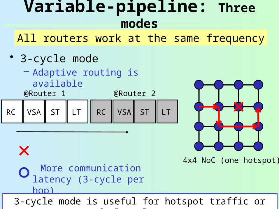
• 3-cycle mode– Adaptive routing is
available
More communication latency (3-cycle per hop)
Hotspots and faulty routers can be dynamically avoided
VSA ST LT ST LT
@Router 1 @Router 2
RC VSARC
4x4 NoC (one hotspot)
3-cycle mode is useful for hotspot traffic or fault tolerance
All routers work at the same frequency
Variable-pipeline: Three modes

• Standard cells– Fujitsu 65nm library– Custom cells (level
shifter, voltage switch)
• Synthesis– Synopsys Design
Compiler• Place and route
– Synopsys Astro• RC extraction
– Cadence QRC• SPICE simulation
– Synopsys HSIM
Variable-pipeline router: Design
VDD
Clock
Select
Current
Fujitsu 65nm (0.8V1.2V, 25C)
Vdd-low
Voltage switch
Clock is stoppedto clearly show energy
Vdd-high

Variable-pipeline: Freq & Vdd levels
• 2-cycle mode– Output buf is enabled
Low performance (2-cycle per hop)
Delay: 1831psec @ 1.2V
Vdd-low: 0.83V
• 1-cycle mode– Output buf is bypassed
High performance (1-cycle per hop)
Delay: 2550psec @ 1.2V
Vdd-high: 1.20V
RC/VSA
ST LT RC/VSA
ST LT
@Router 1 @Router 2
RC/VSA
ST,LT
@Router 1 @Router 2
RC/VSA
ST,LT
All routers work at 392.2MHz
All routers work at 392.2MHz; [email protected]; [email protected]

Outline: Multi-Vdd variable-pipeline router
• Problem of DVFS router– Each router works at different frequency– Communication between different frequency
domains
• Multi-Vdd variable-pipeline router– Voltage and “router pipeline depth” are adjusted– All routers work at the same frequency
• Voltage switch policies:– Low-power policy– Delay variation tolerance using a thermal sensor
• Evaluations– Circuit-level evaluations– System-level evaluations

Policy 1: Standby-power reduction
Vdd transition: 2 cycle
2cycle
Vdd up
Only 1st hop cannot detect packet arrival in advance.2-cycle transfer at 1st hop
• Each router– Notifies the packet
arrival to 2-hop away– Can detect next packet
arrival 2-hop earlier• Packet arrival
detected:– 2-cycle to 1-cycle
(boost)1. Raise the voltage2. Reduce pipeline stage
• After packet transfer:– 1-cycle to 2-cycle (relax)1. Increase pipeline stage2. Reduce the voltage

Policy 1: Standby-power reduction
Vdd transition: 2 cycle
2cycle
Vdd up
1cycle
Only 1st hop cannot detect packet arrival in advance.2-cycle transfer at 1st hop
• Each router– Notifies the packet
arrival to 2-hop away– Can detect next packet
arrival 2-hop earlier• Packet arrival
detected:– 2-cycle to 1-cycle
(boost)1. Raise the voltage2. Reduce pipeline stage
• After packet transfer:– 1-cycle to 2-cycle (relax)1. Increase pipeline stage2. Reduce the voltage

Policy 1: Standby-power reduction
Vdd transition: 2 cycle
2cycle
Vdd up
1cycle1cycle
Only 1st hop cannot detect packet arrival in advance.2-cycle transfer at 1st hop
• Each router– Notifies the packet
arrival to 2-hop away– Can detect next packet
arrival 2-hop earlier• Packet arrival
detected:– 2-cycle to 1-cycle
(boost)1. Raise the voltage2. Reduce pipeline stage
• After packet transfer:– 1-cycle to 2-cycle (relax)1. Increase pipeline stage2. Reduce the voltage

Policy 1: Standby-power reduction
Vdd transition: 2 cycle
2cycle1cycle1cycle1cycle
Only 1st hop cannot detect packet arrival in advance.2-cycle transfer at 1st hop
• Each router– Notifies the packet
arrival to 2-hop away– Can detect next packet
arrival 2-hop earlier• Packet arrival
detected:– 2-cycle to 1-cycle
(boost)1. Raise the voltage2. Reduce pipeline stage
• After packet transfer:– 1-cycle to 2-cycle (relax)1. Increase pipeline stage2. Reduce the voltage
Vdd-low when no packet; 1-cycle@Vdd-high when packets come

Outline: Multi-Vdd variable-pipeline router
• Problem of DVFS router– Each router works at different frequency– Communication between different frequency
domains
• Multi-Vdd variable-pipeline router– Voltage and “router pipeline depth” are adjusted– All routers work at the same frequency
• Voltage switch policies:– Low-power policy– Delay variation tolerance using a thermal sensor
• Evaluations– Circuit-level (area, switching latency & energy, BET)– System-level (application performance, standby
power)

Evaluation: Area overhead
Arbiter
X+
X-
X+
X-
FIFO
FIFO
Vdd select
Vdd-high Vdd-low
Voltage switch
Level shifter
Output buffer bypassing
Pipeline control

Evaluation: Area overhead
Arbiter
X+
X-
X+
X-
FIFO
FIFO
Vdd select
Vdd-high Vdd-low
Voltage switch
Level shifter
Output buffer bypassing
Router Level shifterVoltage switch Total
Original 59.41 0 0 59.41
Proposed 63.13 (*) 4.11 0.54
67.78 (+14.1%)
Hardware amount of original and variable-pipeline routers [kilo gates]
(*) Thermal sensor is not included
Pipeline control

Evaluation: Transition time & energy
• Low to high transition– E.g., 0.8V to 1.2V Transition time:
3.1nsec 231 pJ is consumed
• High to low transition– E.g., 1.2V to 0.8V Transition time:
5.3nsec 148 pJ is charged Energy consumed
Energy charged
Transition energy (left) Transition delay (right)
Vdd-high is 1.2V; Vdd-low ranges 0.6V-1.1V
A pair of voltage transitions consume 83pJ (=231-148) .
Thus, frequent voltage transitions adversely increase the total power consumption.
Break-even time (BET) is the minimum duration time to compensate for the overhead energy (i.e.,
83pJ).
BET is 58nsec (23-cycle @392.2MHz)

CMP simulator: GEMS/Simics• Full-system CMP simulation
– 16-tile CMP, 4x4 mesh NoC– Sun Solaris 9, Sun Studio 12– NAS Parallel Bench (16 threads)
OpenMP version
IS, DC, MG, EP, LU, SP, BT, FT
On-chip router
UltraSPARC
L1 cache (I & D)
L2 cache bank

CMP simulator: GEMS/Simics• Full-system CMP simulation
– 16-tile CMP, 4x4 mesh NoC– Sun Solaris 9, Sun Studio 12– NAS Parallel Bench (16 threads)
OpenMP version
IS, DC, MG, EP, LU, SP, BT, FT
On-chip router
UltraSPARC
L1 cache (I & D)
L2 cache bank
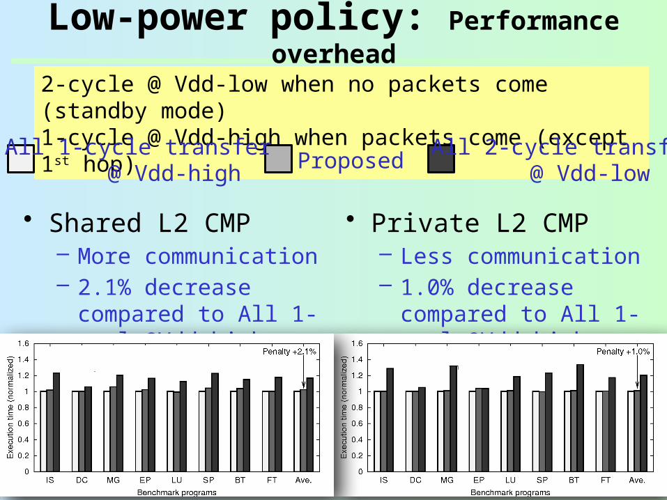
• Shared L2 CMP– All L2 cache banks are shared by all tiles– More communication between tiles
• Private L2 CMP– Every tile has its own private L1 and L2 caches– Less communication between tiles

Low-power policy: Performance overhead
ProposedAll 1-cycle transfer All 2-cycle transfer
@ Vdd-high @ Vdd-low
2-cycle @ Vdd-low when no packets come (standby mode)1-cycle @ Vdd-high when packets come (except 1st hop)
Low-power policy: Performance overhead
2-cycle @ Vdd-low when no packets come (standby mode)1-cycle @ Vdd-high when packets come (except 1st hop) Proposed
All 1-cycle transfer All 2-cycle transfer@ Vdd-high @ Vdd-low
• Shared L2 CMP– More communication– 2.1% decrease
compared to All 1-cycle@Vdd-high
• Private L2 CMP– Less communication– 1.0% decrease
compared to All 1-cycle@Vdd-high

Low-power policy: Standby power reduction
ProposedAll 1-cycle transfer All 2-cycle transfer
@ Vdd-high @ Vdd-low
2-cycle @ Vdd-low when no packets come (standby mode)1-cycle @ Vdd-high when packets come (except 1st hop)

• Shared L2 CMP– More communication– 10.4% reduction
compared to All 1-cycle@Vdd-high
• Private L2 CMP– Less communication– 44.4% reduction
compared to All 1-cycle@Vdd-high
Low-power policy: Standby power reduction
ProposedAll 1-cycle transfer All 2-cycle transfer
@ Vdd-high @ Vdd-low
Frequent short-term transitions less than
BET
2-cycle @ Vdd-low when no packets come (standby mode)1-cycle @ Vdd-high when packets come (except 1st hop)

• Existing DVFS router– Voltage and frequency are adjusted
• Multi-Vdd variable-pipeline router– Voltage and “router pipeline depth” are adjusted– All routers work at the same frequency
• Voltage switch policies:– Low-power policy, and delay variation tolerance
policy• Evaluation results:
– Area overhead is 14.1%; Break-even time is 23 cycles
– Performance degradation 1.0% to 2.1%– Standby power reduction 10.4% to 44.4%
Summary: Multi-Vdd variable-pipeline router
Communication between different frequency domains introduces some difficulties…

On-going work• Thermal sensor design
– Oscillation-Ring based Thermal Sensor (ORTS)
• More sophisticated policies– Take into account Break-even time (BET) to avoid
inefficient voltage transitions– E.g., Tied to 1-cycle@Vdd-high for high-volume
traffic• Finer-grained multi-Vdd control
– E.g., input channel or VC level to exploit traffic locality
[Yang,ASPDAC’09]
[Wolpert,NOCS’10]
Enable
Pulse counter Thermal level