A multi-sensor traffic scene dataset with omnidirectional...
9
A multi-sensor traffic scene dataset with omnidirectional video Philipp Koschorrek, Tommaso Piccini, Per Öberg, Michael Felsberg, Lars Nielsen and Rudolf Mester Linköping University Post Print N.B.: When citing this work, cite the original article. Original Publication: Philipp Koschorrek, Tommaso Piccini, Per Öberg, Michael Felsberg, Lars Nielsen and Rudolf Mester, A multi-sensor traffic scene dataset with omnidirectional video, 2013. From the IEEE Conference on Computer Vision and Patter Recognition: Workshop on Ground Truth, June 28, 2013, Portland, U.S.A. ©2013 IEEE. Personal use of this material is permitted. However, permission to reprint/republish this material for advertising or promotional purposes or for creating new collective works for resale or redistribution to servers or lists, or to reuse any copyrighted component of this work in other works must be obtained from the IEEE. Postprint available at: Linköping University Electronic Press http://urn.kb.se/resolve?urn=urn:nbn:se:liu:diva-93277
-
Upload
duongnguyet -
Category
Documents
-
view
221 -
download
2
Transcript of A multi-sensor traffic scene dataset with omnidirectional...

A multi-sensor traffic scene dataset with
omnidirectional video
Philipp Koschorrek, Tommaso Piccini, Per Öberg, Michael Felsberg, Lars Nielsen and Rudolf
Mester
Linköping University Post Print
N.B.: When citing this work, cite the original article.
Original Publication:
Philipp Koschorrek, Tommaso Piccini, Per Öberg, Michael Felsberg, Lars Nielsen and Rudolf
Mester, A multi-sensor traffic scene dataset with omnidirectional video, 2013.
From the IEEE Conference on Computer Vision and Patter Recognition: Workshop on
Ground Truth, June 28, 2013, Portland, U.S.A.
©2013 IEEE. Personal use of this material is permitted. However, permission to
reprint/republish this material for advertising or promotional purposes or for creating new
collective works for resale or redistribution to servers or lists, or to reuse any copyrighted
component of this work in other works must be obtained from the IEEE.
Postprint available at: Linköping University Electronic Press
http://urn.kb.se/resolve?urn=urn:nbn:se:liu:diva-93277

A multi-sensor traffic scene dataset with omnidirectional video
Philipp Koschorrek1, Tommaso Piccini1, Per Oberg2, Michael Felsberg1, Lars Nielsen2, Rudolf Mester1,31Computer Vision Laboratory, Dept. of Electrical Engineering, Linkoping University, Sweden
2Vehicular Systems, Dept. of Electrical Engineering, Linkoping University, Sweden3VSI Lab, Computer Science Dept., Univ. Frankfurt, Germany
{firstname}.{lastname}@liu.se
Abstract
The development of vehicles that perceive their environ-ment, in particular those using computer vision, indispens-ably requires large databases of sensor recordings obtainedfrom real cars driven in realistic traffic situations. Thesedatasets should be time shaped for enabling synchroniza-tion of sensor data from different sources. Furthermore,full surround environment perception requires high framerates of synchronized omnidirectional video data to preventinformation loss at any speeds.
This paper describes an experimental setup and softwareenvironment for recording such synchronized multi-sensordata streams and storing them in a new open source for-mat. The dataset consists of sequences recorded in variousenvironments from a car equipped with an omnidirectionalmulti-camera, height sensors, an IMU, a velocity sensor,and a GPS. The software environment for reading these datasets will be provided to the public, together with a collectionof long multi-sensor and multi-camera data streams storedin the developed format.
1. IntroductionComputer vision is evolving into a key technology for
the automotive area, starting from simple, mostly visual-ization related tasks such as rear cameras, to driver assis-tance functionalities like lane-keeping assistants, traffic signrecognition, and soon including the field of visually guidedautonomous driving. It is obvious already today that multi-ple cameras will be present in future cars, thus allowing tomonitor the complete 360◦ field of view of a car in flow-ing traffic, detect dangerous situations and increase safetyand comfort in driving. These prospects depend cruciallyon the availability of intelligent algorithms, evaluated andoptimized on data of real traffic situations.
Building a dynamic environment model from a stream ofdata coming from a set of cameras looking into multiple di-rections around a vehicle is a challenging problem. Further
Figure 1. Test platform car with roof rack mounted Ladybug 3
challenges arise from the immense variability of scenes un-der different weather and illumination situations, consider-ing occlusions and sensor imperfections, that make imagesdifficult or ambiguous to be interpreted.
In order to develop robust and reliable algorithms forcamera based environment sensing and interpretation inmulti-view scenarios, large realistic datasets are needed.
Our contributions are a framework for storing synchro-nized multi-sensor multi-camera data and example datasets,suitable for testing solutions to tasks such as visual odom-etry, SLAM, sensor fusion, motion estimation and opticalflow computation.
Such datasets provide several significant benefits:
• It is possible to test algorithms from a real experimen-tal car without investing time and money to actuallybuild such a setup and record sequences with it.
• Evaluation on a standard dataset allows direct compar-ison of algorithms and methods.
• Thanks to redundant sensors, ground truth for e.g. ego-motion can be determined by sensor fusion.
Data that is of primary interest besides video is a) thetrue ego-motion of the car w.r.t. the static environment, andb) the true 3D structure of the environment, including thestatic scene and other moving objects.
1

1.1. Motivation
Our aim is to develop algorithms working in real urbanor highway traffic situations, including high speed ranges.Hence, high frame rates and real traffic sequences areneeded. Since none of the existing datasets provides suchinformation in a way which also allows real time simula-tions, we decided to provide a new dataset, aimed mainly atvisual odometry applications. The dataset features the kindof information we consider to be lacking in previous work,and a flexibility that allows to represent any kind of mul-tisensor setups in the same framework. The experimentalsetup we used includes an omnidirectional camera, an IMU,laser-based height sensors, a velocity sensor based on opti-cal road surface correlation, and a GPS receiver, mountedon a roadworthy car allowing us to take part in real traf-fic situations. All recorded data are stored in a new, flex-ible format using common timestamps, which makes realtime playbacks possible. We provide also the necessarysoftware environment and APIs to access data for differentpopular programming languages. Existing algorithms forvisual odometry with a similar setup like the one proposedof Tardif et al. [7] can be revisited and compared against acommon ground truth, even when driving in regions whereabsolute reference (e.g. GPS) is not available.
1.2. Ground Truth
While the 6D pose can be extracted from auxiliary sen-sors, by design, we chose not to include such informationin our dataset. This choice is dictated by our view on whatshould be considered ground truth. In the case of real lifescenarios we do not have access to the true model parame-ters (as we have for synthetic data) and we have to rely onmeasurements and sensor data from independent sensors.Moreover those may be afflicted by accidental or system-atic distortions in the measuring procedure or in the sensorreadings. At best, these distortions are statistically inde-pendent of the measurements under assessment. Also sincethe state-of-the-art in fusion methods continuously evolves,storing raw data instead of processed data ensures sustain-ability. We therefore prefer to leave the choice on the algo-rithm to determine ’ground truth’ to each final user of ourdata, while groups interested in sensor fusion may gain in-terest in our data and contribute to a, possibly evolving, goldstandard for ground truth in our sequences. Another factorthat brought us to our choice is that it is generally preferableif ground truth is extracted from the data by an indepen-dent third party as suboptimal ground truth can constitute astrong bias in algorithm evaluation. For all these reasons,we decided to store the raw sensor recordings.
While we are using mid-level IMU and GPS sensors,they can be fused with further high accuracy sensor data(height and speed sensors, 2.1) to obtain ground truth.
Similarly, the available data can be used for evaluating
Structure-From-Motion (SFM) algorithms. While we donot provide any ground truth for the 3D structure of thescenarios, a highly accurate model can be obtained fromstate-of-the-art bundle adjustment on all data of a sequencetogether with the provided calibration parameters. Such amodel may be useful for evaluations of SFM algorithms onsubsets of data of the corresponding sequence. A similarapproach is used in Middlebury data [5].
1.3. Related work
Automotive, vision related datasets have been publishedby different research groups in the past few years.
The KITTI dataset and benchmark suite [3] providescombined IMU and GPS data, point clouds produced by alaser scanner and stereo visual data in both grayscale andcolor format. The primary aim of the KITTI dataset is, how-ever, to provide a benchmark suite for the testing of com-puter vision algorithms on real automotive applications. Itis thus composed of several short sequences consisting inchallenges of levels of difficulty for algorithms. Though thisis an ideal approach for testing and benchmarking of algo-rithms, when the aim is the design of robust, industry ori-ented software, much longer and diverse sequences showingas various situations as possible are needed. For compari-son, the size of the whole KITTI dataset is of approximately20GB, about equivalent to the size of our shortest sequenceafter compression.
Blanco et al. present in [1] a dataset with a focus on”centimeter-accuracy ground truth” of position data for test-ing SLAM algorithms designed for small mobile robots.Their dataset is composed of synchronized data comingfrom multiple sensors (color cameras, laser scanners, differ-ent kinds of GPS receivers and IMU sensors) and providedin a structured, plain text file based format together withan API to handle the data. The data is, however, taken atslow speeds from a steady and controlled environment suchas a university campus and a parking lot. In a later exten-sion of their work, data has been gathered also for a longersequence taken in a urban scenario1. Their setup misses,however, the omnidirectional visual data that we considerof fundamental importance for full surround sensing.
We identified only two publicly available datasets thatshow significant affinity to our work. One is the work pre-sented by Smith et al. [6]. Visual and inertial data is gath-ered with a multisensor setup based on a Segway like vehi-cle driven through the New College Campus in Oxford, UK.The dataset comprises odometry information, GPS data andpoint clouds provided with a couple of laser scanners to-gether with visual data coming from both a stereo pair ofgrayscale cameras at 20 frames per second (fps) and an om-nidirectional color camera (3 fps). The dataset is providedin a structured format where the sensor readings are in a
1http://www.mrpt.org/MalagaUrbanDataset

time stamped, time ordered text file, separated from the vi-sual data. This approach is very similar to our own, but theplain text format used introduces a lot of unnecessary re-dundancy in the data which also results in a increased sizeof the files while giving in exchange only a small advance indata handling. Pandey at al. [4] published a second datasetsimilar to our own. They provide recordings of omnidirec-tional visual data at 8 fps together with laser scans and in-ertial sensor readings. The data presented have, however,to be synchronized in post-processing since the readings ofthe sensors are stored separately. Furthermore the datasetconsists only of two sequences.While the merits of these two works are undeniable, theyboth still fall short in aspects that we consider of primaryimportance, such as the frame rate of the omnidirectionalvisual data, the environment chosen for the data recordingsand the possibility for real-time simulation. The omnidi-rectional visual data is provided at only 3 and 8 fps respec-tively, and in both cases the sequences were recorded insidethe respective university campuses where no other or onlyfew vehicles are present. The vehicle speed and the vari-ability of the surrounding landscape within the sequences,as well as between the sequences, is low compared to ourdataset. Furthermore their APIs do not provide a comfort-able method for the streaming of the data.
2. Experimental setupIn this section, we provide a detailed description of our
experimental setup in both hardware and software aspects.
2.1. Hardware
The dataset was recorded with a Volkswagen Golf 5 (Fig.1) equipped with an omnidirectional multi-camera system,a Point Grey Ladybug 32 (C), and several sensors recordingthe motion of the car both in the car’s own frame of refer-ence and a global coordinate system. The camera consistsof 6 synchronized global shutter color cameras configuredto a raw resolution of 616 × 1616 pixel (width × height)each, stored as Bayer images. While one camera is pointingupwards and will be of marginal interest for most applica-tions, the five remaining cameras depict the horizontal sur-roundings of the car. The arrangement of the cameras withoverlapping fields of view allows a 360◦ view of the envi-ronment. The frame rate of 30 fps is much higher than insimilar datasets [6, 4].Such a setup is chosen for the flexibility it provides. Whilean omnidirectional camera positioned on the roof of a carwill hardly be the choice of a car producer, experimentallyit allows to simulate any case of camera setting with slightlyoverlapping fields of view. Omnidirectional stereo vision istheoretically possible using two LadyBug cameras stacked
2http://www.ptgrey.com/products/ladybug3/
on top of each other, but this is practically unfeasible dueto mechanical and data-rate constraints. Localized stereovision, on the other hand, could be easily introduced in thefuture, if deemed necessary, by e.g. adding a single forwardlooking camera.
Several other sensors complement the camera in order toobtain an extended and redundant set of measurements fromwhich egomotion and dynamic attitude can be computed.The sensors are the following:
• camera mounted IMU• lateral & longitudinal velocity sensor (car front)• three non contact laser ride height sensors (side doors
and car front)• GPS receiver
Figure 2 shows the mechanical setup, whereas the sensorsetup of the car is shown in Figure 3, with the multi-camerarig being shifted in the drawing from the roof. A more de-tailed sketch of the car setup can be found on the projectwebsite (see Section 4).
Figure 2. Mechanical setup: C - Camera, I - IMU, G - GPS re-ceiver, HR, HL, HF - Height sensors, VF - Velocity sensor
The XSens MTi AHRS3 (I) is an IMU with 9 channelswhich measures the acceleration, angular velocity and mag-netic field in all three directions of its internal coordinatesystem. The velocity sensor (VF) and the height sensorsmounted at the front (HF) and at the side doors (HR, HL,right and left respectively) of the car provide additional in-formation such as more accurate estimates for the attitudeand speed of the car to optimize and stabilize state estima-tions based on IMU data. Additionally to the longitudinalvelocity VF measures the lateral velocity, too. The heightsensors are mounted on the front and the sides of the carallowing an estimation of the roll and pitch angle of the car.The velocity sensor, a Kistler Correvit S-350 Aqua, and theheight sensors, Kistler HF-500C, are parts of the 3-axis op-tical measurement system by Corrsys Datron4. The GPS re-ceiver is a uBlox AEK-4P GPS development kit using onlypure GPS information without RTK correction signals.The Ladybug camera has been setup in such a way that onecamera points in the forward direction of the car, while theviewing directions of the four remaining cameras are to the
3http://www.xsens.com/en/general/mti4http://www.corrsys-datron.com/optical sensors.htm

side and rear of the car with an angle of 72◦ between ad-jacent cameras. Due to the distances between the sensors,each sensor has to be described in its own coordinate sys-tem. These coordinate systems are named after the sensorsplus a suffix e.g. HRCS, HLCS, etc. All sensor coordinatesystems are right-handed and set in reference to the coordi-nate system of the car (CARCS) which lies in the geometriccenter of the bounding box of the car chassis, i.e., the carwithout tires and suspension. CARCS is also a right-handedcoordinate system where the x-axis is pointing forward andthe y-axis to the right of the car whereas the axes are parallelto the bounding box edges of the car. The attitude of the cardescribes the rotation of this coordinate system to a coor-dinate system SCS which lies on the street with x pointingforward and z parallel to the downwards directed surfacenormal, i.e. to the model of a plain street. The relationsof the sensor coordinate systems to the car reference frameas well as the calibration data of the camera done with theframework provided by [2] can be found on the project webpage, see Section 4. Furthermore, the known calibrationparameters allow us to merge the six camera recordings ac-cording to different camera models, e.g. panorama images,dome projections or spherical projections. The samplingfrequencies FSi of the different sensors are shown in Table1.
Table 1. Sampling frequenciesSensor FSi[Hz]
C 30I 100
VF 250HR, HL, HF 250
GPS ∼ 4
Furthermore, the car internal CAN (Controller Area Net-work) bus messages are recorded in raw format, too, but arenot yet further processed.The measurements gathered by the IMU and GPS have notbeen combined. The absolute position and velocity of thecar in the world reference frame obtained by the GPS mod-ule and the measured IMU data in its coordinate system arestored separately. Attitude estimates for the IMU and, dueto their rigid coupling, also for the camera are produced bythe internal Kalman Filter of the IMU and stored, as well.Obviously a fusion of all sensor data or at least a few, e.g.IMU and GPS, would improve the accuracy of the estimatedposition, but it has not been applied due to the reasons al-ready mentioned in Section 1.2.The sensors acquire their measurements continuously at thementioned sampling frequencies and send them to a com-puter, which is referred to as LinCom in the following.
The camera is connected via FireWire to and controlledfrom a second computer, WinCom, controlling only themulti-camera due to high necessary data rates. LinCom
is controlling and reading the remaining sensors to obtainmeasurements in real-time. Both computers are connectedvia Ethernet in a Local Area Network in order to providetime synchronization.
Figure 3. Sensor arrangement scheme
2.2. Software
This section describes the software running on the differ-ent computers as well as the method to synchronize them.
Data synchronization For the combination of sensor dataand images, it is necessary that they share the same timebase. In consequence of the need of two computers, theirinternal clocks have to be synchronized to achieve this goal.In order to provide high accuracy, a synchronization viaNetwork Time Protocol (NTP) was chosen. LinCom wasadapted to act as a NTP server sending out time informa-tion. The stratum value of the NTP server was set very lowto make sure that the connected computer, WinCom, truststhe time signal. Obviously it is not necessary to have an ac-curate global time, rather it is necessary for the computers toshare the same time. LinCom sends out its own kernel timeas time base and WinCom is synchronizing to this time. Thetime difference between the computers achieved with thismethod is, according to the NTP client, below 2ms.Further time information such as global time (UTC) can beextracted from GPS recordings if this is required.
WinCom WinCom runs Windows 7 as operating system,as this is necessary for accessing the API of the Ladybug3camera with the full feature set. A recording program waswritten in C/C++ to grab the images of the camera and storethem. Besides the image handling, the software also recordsthe time at which the image was grabbed. This time cor-responds, except for the mentioned synchronization uncer-

tainty, to the kernel time of LinCom. With those time val-ues and corresponding time stamps in the recordings of Lin-Com, a merging of the sensor data and image informationis possible. Extra camera information, such as the shuttertime, is also stored with the images.
LinCom A Gentoo Linux distribution without graphicaluser interface is running on LinCom to achieve maximalperformances while having all benefits of a modern operat-ing system. A real-time Linux could not been used sincethere are no real-time Linux USB stacks. The measurementprogram was written in C/C++ using the Boost5 library andthe APIs of the sensors and interface devices for CAN. Itis thread-based for simultaneous event-based reading of allsensors. In consequence of the asynchronous transmissionof the sensor data, it is necessary that all functions whichcollect measurements are running in parallel. Otherwise itcannot be avoided that sensor data capture is delayed, oreven data is lost. The principal structure of the programhas been adopted from [8] whereas now each sensor is as-signed to its own thread, which waits in a loop for incomingdata. After the reception of data, the current kernel time isdetermined and the difference of the current time and a ref-erence time (the start of the measurement program) is usedto calculate a time stamp of the incoming message which isstored together with the sensor data. After reading the rawdata and calculating the time stamp of these messages, thereadings are converted in physical values with a given unitof measure, e.g. [ms2 ] for acceleration or m
s for velocity. Inthe next step the time stamp, a unique identifier describingthe sensor data and the converted data are written to a stringand stored temporarily in a thread-coupled FIFO memory.Each sensor thread deals with the data like this. A round-robin scheduled thread periodically reads out the FIFOs oneby one and stores the contained data strings in a CSV file.
3. Dataset structureTo the best of our knowledge, a standard file format for
the storage of large image sequences with additional syn-chronized data such as IMU or GPS data has not been pro-posed in the public yet. There are already available, relatedstoring methods such as the one used by ROS6, bag files,which are capable of storing different kinds of data. Weconsidered to store the data as bag files, but this has severedisadvantages, among which the fact that it is not stable onall platforms and only fully supported for Ubuntu Linux.Since ROS is needed to read the bag files, parts of the pro-gram have to be ROS nodes. Furthermore, the data wouldonly be accessible through ROS topics. Hence a set of staticROS message definitions and publisher would be needed
5http://www.boost.org/6http://www.ros.org/
additionally to the bag file for describing the ROS messagestructure and publishing the topics. This makes usage ofROS less flexible here than our approach in terms of addingnew sensors. The major problem though, is the size of thedata. Due to the high data rates and the large number ofcameras, the bag files would be monolithic files with sev-eral Gigabytes in size.The format proposed here, the LiU Stream Format , in-stead, handles such combined data recordings under theconstraints given by different file systems such as FAT32,NTFS, ext3 and ext4, on which a storage of the datasetshould be possible. The images are stored as standard im-age files in a hierarchical but transparent folder structure toachieve a limited number of files per folder. The additionalsensor data are stored in linked binary files, called streamfiles, organized as message blocks in temporal order. Wepropose this format as an Open Source format and provideAPIs to read from it, as well as guidelines for expanding ourwork.
3.1. Stream File
In the stream file, each message corresponds to one mea-surement at a certain time and has a specific frame format(Figure 4).
Figure 4. Format of a streamfile message
Each message consists of a header composed of threefixed parts: a block start signal ($BST), an identifier anda length variable. The block start is a unique character se-quence to identify the begin of a message. It should not betoo long to waste memory and not to short to avoid mis-matches with random data. The identifier, the ID, describesthe kind of message, i.e. the content of the message. Con-nected to a certain ID is a specific message structure as wellas a specific sensor. Subsequent to the ID, the length ofthe message payload in bytes is stored. The actual messagecalled payload follows; it is sensor- and user-dependent andcan vary from sensor to sensor. Payloads have been speci-fied for the sensors we used so far. As an example, Table 2shows the payload format for IMU recordings. This payloadis 80 byte long whereas the first 8 bytes are one unsigned intvalue and each of the following 8 bytes are double values.
All message payload structures, their corresponding IDsand additional information are described in a XML-filewhich is used to initialize the reading of the stream file, butserves also to describe the structure in a format accessibleto human readers, and finally allows also ID and messagepool expansion. This file is available together with the dataset and the API; see more in Section 4.
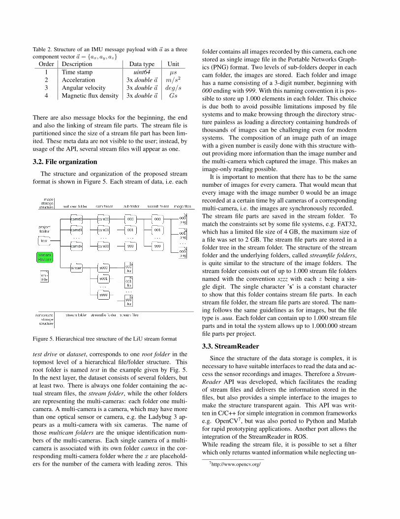
Table 2. Structure of an IMU message payload with ~a as a threecomponent vector ~a = {ax, ay, az}
Order Description Data type Unit1 Time stamp uint64 µs2 Acceleration 3x double ~a m/s2
3 Angular velocity 3x double ~a deg/s4 Magnetic flux density 3x double ~a Gs
There are also message blocks for the beginning, the endand also the linking of stream file parts. The stream file ispartitioned since the size of a stream file part has been lim-ited. These meta data are not visible to the user; instead, byusage of the API, several stream files will appear as one.
3.2. File organization
The structure and organization of the proposed streamformat is shown in Figure 5. Each stream of data, i.e. each
Figure 5. Hierarchical tree structure of the LiU stream format
test drive or dataset, corresponds to one root folder in thetopmost level of a hierarchical file/folder structure. Thisroot folder is named test in the example given by Fig. 5.In the next layer, the dataset consists of several folders, butat least two. There is always one folder containing the ac-tual stream files, the stream folder, while the other foldersare representing the multi-cameras: each folder one multi-camera. A multi-camera is a camera, which may have morethan one optical sensor or camera, e.g. the Ladybug 3 ap-pears as a multi-camera with six cameras. The name ofthose multicam folders are the unique identification num-bers of the multi-cameras. Each single camera of a multi-camera is associated with its own folder camxx in the cor-responding multi-camera folder where the x are placehold-ers for the number of the camera with leading zeros. This
folder contains all images recorded by this camera, each onestored as single image file in the Portable Networks Graph-ics (PNG) format. Two levels of sub-folders deeper in eachcam folder, the images are stored. Each folder and imagehas a name consisting of a 3-digit number, beginning with000 ending with 999. With this naming convention it is pos-sible to store up 1.000 elements in each folder. This choiceis due both to avoid possible limitations imposed by filesystems and to make browsing through the directory struc-ture painless as loading a directory containing hundreds ofthousands of images can be challenging even for modernsystems. The composition of an image path of an imagewith a given number is easily done with this structure with-out providing more information than the image number andthe multi-camera which captured the image. This makes animage-only reading possible.
It is important to mention that there has to be the samenumber of images for every camera. That would mean thatevery image with the image number 0 would be an imagerecorded at a certain time by all cameras of a correspondingmulti-camera, i.e. the images are synchronously recorded.The stream file parts are saved in the stream folder. Tomatch the constraints set by some file systems, e.g. FAT32,which has a limited file size of 4 GB, the maximum size ofa file was set to 2 GB. The stream file parts are stored in afolder tree in the stream folder. The structure of the streamfolder and the underlying folders, called streamfile folders,is quite similar to the structure of the image folders. Thestream folder consists out of up to 1.000 stream file foldersnamed with the convention szzz with each z being a sin-gle digit. The single character ’s’ is a constant characterto show that this folder contains stream file parts. In eachstream file folder, the stream file parts are stored. The nam-ing follows the same guidelines as for images, but the filetype is .uuu. Each folder can contain up to 1.000 stream fileparts and in total the system allows up to 1.000.000 streamfile parts per project.
3.3. StreamReader
Since the structure of the data storage is complex, it isnecessary to have suitable interfaces to read the data and ac-cess the sensor recordings and images. Therefore a Stream-Reader API was developed, which facilitates the readingof stream files and delivers the information stored in thefiles, but also provides a simple interface to the images tomake the structure transparent again. This API was writ-ten in C/C++ for simple integration in common frameworkse.g. OpenCV7, but was also ported to Python and Matlabfor rapid prototyping applications. Another port allows theintegration of the StreamReader in ROS.While reading the stream file, it is possible to set a filterwhich only returns wanted information while neglecting un-
7http://www.opencv.org/

wanted ones. Another possibility is an image-only readingif the interest is focused on visual data, since the image pathdepends only on the image and camera number.Besides the API and the datasets, two XML files are needed:one containing all available IDs and messages, their struc-tures and their corresponding IDs and a second one whichstores the paths to the dataset and to the first XML file andis used to initialize the StreamReader.
4. Data accessThe present dataset consists of 7 sequences which have
been recorded in different environments, traffic situationsand test paths. Two sequences provide several loop closuresituations, whereas the others have been recorded on mainstreets with both low and higher traffic volume. A shortdescription of all 7 sequences is given in Table 3.
Table 3. Recorded sequences
Name Length # Frames Size SpecificsSeq1 0.7km 4180 45 GB loop closingSeq2 2.9km 9826 106 GB medium trafficSeq3 1.4km 6689 72 GB loop closingSeq4 4.6km 21912 236 GB rush hourSeq5 ca. 1.4km 6469 70 GB low trafficSeq6 ca. 4.3km 19487 210 GB snow on lens
high trafficSeq7 ca. 9.1km 39830 430 GB long sequence
Figure 7 shows example images of the five horizontalcameras (the one pointing upward was disregarded). Theimages are stored in Bayer format in order to achieve a min-imum of redundancy and information loss. Example trafficsituations from the dataset are shown in Fig. 8 as panoramicimages composed from single images with the Point GreyLadybug 3 SDK. Figure 6 shows examples of the recordingsof the GPS, velocity sensor and IMU (yaw rate) of a similarsequence where the car has been driven three laps around abuilding.
The APIs for the mentioned programming languages(C/C++, Matlab, Python and as ROS node) and the tech-nical documentation are made available together with thesequences. The documentation contains
• a description of the sequences,• a detailed sketch of the experimental setup,• a camera calibration parameter file,• a detailed description of the stream format,• a description of the APIs functions and• a list of IDs and message structures.
All these details are publicly available on our website 8.8http://www.cvl.isy.liu.se/research/datasets/must
Figure 6. Sensor recordings: GPS recordings (top), Speed datafrom velocity sensor (middle), Yaw rate from IMU (bottom)
Figure 7. Sample images showing the surrounding of the car
The size of the data recorded so far does not allow us to pub-lish all sequences on a website. However, short sample se-quences can be downloaded from the website, and instruc-tions on how to obtain the full dataset are provided there aswell.
5. Concluding remarksIn this work, we presented two contributions which will
help to advance the technology of visual environment sens-ing for vehicles. The first contribution is the publication

Figure 8. Scenes with different traffic and weather conditions as stitched and clipped panoramic images
of sequences recorded with our experimental car, which al-lows the community to test and prototype multi-sensor dataprocessing procedures even without having access to an ex-perimental vehicle and the recording hardware. The sec-ond contribution is a by-product of our dataset: a versatilemulti-purpose dataset API, which allows to record and re-produce asynchronous time stamped multi-sensor data, in-cluding multiple cameras.
Benchmark testing of methods that use asynchronoustime stamped multi-sensor data can be done in a quasi-standardized way in different research groups. In the longrun, this may support the circulation of methods which havebeen tested under truly realistic situations, and which actu-ally make the leap from an academic development environ-ment into real systems. We hope that other groups will ex-tend the pool of datasets using their vehicles, sensors andcameras. The proposed scheme for organizing the data ingeneral stream files supports the idea that other groups pro-vide similar data in a compatible format.
Future work
The presented sequences are larger than most existingones today, but there is a need for even more extensive dataand we will record more datasets from diverse real trafficsituations in various weather, surrounding and traffic condi-tions. We also plan, in the future, to increase sensor redun-dancy in our data for both egomotion and surround sensing,with the aim of allowing a more precise ground truth extrac-tion. Parts of this data, with an emphasis on long sequences,will be made available to the scientific community.
Acknowledgments
This work has been funded by the Swedish ExcellenceCenter at Linkoping - Lund in Information Technology
(ELLIIT) and the Linnaeus research environment for Con-trol, Autonomy and Decision-making in Complex Systems(CADICS) at Linkoping University.
References[1] J.-L. Blanco, F.-A. Moreno, and J. Gonzalez. A collection
of outdoor robotic datasets with centimeter-accuracy groundtruth. Autonomous Robots, 27(4):327–351, November 2009.
[2] J. Y. Bouguet. Camera calibration toolbox for Matlab, 2008.[3] A. Geiger, P. Lenz, and R. Urtasun. Are we ready for au-
tonomous driving? the KITTI vision benchmark suite. InComputer Vision and Pattern Recognition (CVPR), Provi-dence, USA, June 2012.
[4] G. Pandey, J. R. McBride, and R. M. Eustice. Ford campusvision and lidar data set. International Journal of RoboticsResearch, 30(13):1543–1552, November 2011.
[5] D. Scharstein and R. Szeliski. High-accuracy stereo depthmaps using structured light. In Computer Vision and PatternRecognition, 2003. Proceedings. 2003 IEEE Computer Soci-ety Conference on, volume 1, pages I–195. IEEE, 2003.
[6] M. Smith, I. Baldwin, W. Churchill, R. Paul, and P. Newman.The new college vision and laser data set. The InternationalJournal of Robotics Research, 28(5):595–599, May 2009.
[7] J.-P. Tardif, Y. Pavlidis, and K. Daniilidis. Monocular vi-sual odometry in urban environments using an omnidirec-tional camera. In Proc. IEEE/RSJ International Conferenceon Intelligent Robots and Systems (IROS08), 2008.
[8] J. Wiklund, K. Nordberg, and M. Felsberg. Software architec-ture and middleware for artificial cognitive systems. In Inter-national Conference on Cognitive Systems, 2010.


![· [4] Perazzi et al, A benchmark dataset and evaluation methodology for video object segmentation. CVPR, 2016 [5] Zhou et al. Scene parsing through ade20k dataset. CVPR, 2017 [6]](https://static.fdocuments.us/doc/165x107/5f53a69678df690bcf0b90cb/4-perazzi-et-al-a-benchmark-dataset-and-evaluation-methodology-for-video-object.jpg)