Muscle Anatomy 2014. Skeletal Muscle Cardiac Muscle Smooth Muscle.

A Multi-Sensor Armband based on Muscle andMotion Measurements
James CannanSchool of Computer Science & Electrical Engineering
University of Essex, Colchester CO4 3SQ, UKEmail: [email protected]
Huosheng HuSchool of Computer Science & Electrical Engineering
University of Essex, Colchester CO43SQ, UKEmail: [email protected]
Abstract—This paper presents two simple approaches forfusing together motion and muscle (EMG) sensors to enhancecontrol. The first approach fuses Gyro and EMG sensors toprovide relative control, while the second approach fuses EMG,Accelerometer and Magnetometer for absolute control. A wear-able prototype armband was developed which incorporates allthe sensors. The armband enables any user with some level ofyaw and pitch arm movements, as well as arm muscle voluntarycontraction, to control an electrical device like a computer, arobotic arm, or a mobile phone. Simple data calculation from themotion sensors outputted pitch and yaw, while EMG thresholdbased techniques were used for a virtual enter button. The sensorfusion aims to create intuitive control, while not overcomplicatingthe design process. The interface was connected to a roboticarm and compared against other classical industrial controlapproaches.
Keywords Human-Machine Interface (HMI), Electromyog-raphy(EMG), Accelerometer, Magnetometer, Teleoperation.
I. INTRODUCTION
Robotic teleoperation indicates the remote manipulation of arobot by a human operator at a distance. It has a wide range ofapplications in dangerous and hazard environments, includingspace and deep sea exploration, fire fighting, heavy objectmanipulation, simulation, surgery and training. Keyboardsand Joysticks are traditionally used for robotic teleoperation,however they are inconvenient, as the user is required to carrya joystick of some form. Situations where a clear view ofrobotic operation is required, a control platform or joystickhas the potential to obstruct a user. An alternative wearableinterface that would have direct control of the robot is verybeneficial and may speed up operations.
In robotic applications, classical interfaces do not naturallyinterface with a human operator, hence alternative more intu-itive interface implementations are designed. Robotics witha similar degree of motion as a human, would be moreintuitively controlled with a device that is not restricted to adesk top, therefore, human motion is ideally suited to controlsimilar robotic motions. This type of interface is perfectlysuited for a robotic arm and hand/gripper teleoperation.
For most people it is incredibly easy to move their arms.This natural ability can be exploited to give a human operatoran easy to use interface to control a robot. This would allowa user to move his/her hand in a natural way, while a robot
mimics the same motion. In this manner, the user is able tocontrol an application with minimal training.
Computer vision, speech recognition, motion and bionicinterfaces, are just a few of the available control technologiesthat generate very interesting HMI applications [11][3]. Theyhave great potential to one day interface with our bodies ina non-obtrusive way, while providing unparalleled control inapplications. Current technology limitations have motivateddesigners to combine sensors for a synergistic effect, forinstance combining Accelerometer and EMG sensors [15].
We describe in this paper, two sensor fusion input armbanddevices with the ability to be used by any individual with somelevel of arm movement and arm voluntary muscle contractioncontrol. The users hand motion provides a natural and effectiveway to precisely manipulate the robot with very little training.The devices are called GE-Fusion (Gyro and EMG Fusion)and MEA-Fusion (Magnetometer, EMG and Accelerometer)Bands, both are combined into a small project box withaccompanying surface EMG electrodes, as shown in Figure1. It has many potential applications and is designed to besimple to build and easy to use.
The rest of the paper is organized as follows. Section IIpresents some background about motion control and EMG,while validating the potential of sensor fusion for improvedcontrol. In Sections III, the design of a functional prototypeFusion Band is described, along with equations required foroperation. Section IV, describes results of an experiment usingthe GE and MEA Fusion bands to control a robotic arm andgripper. Discussion of results are given in Section V to analyzethe usability of the interfaces for robotic control. Finally, abrief conclusion and future work is presented in Section VI.
II. BACKGROUND
A lot of research on teleoperation has previously takenplace, the majority focus on traditional input devices, buta few have diverged into areas of computer vision and ex-oskeletal interfaces. Motion capturing technologies exist whichcan track motion without having to interfere with the user.However the performance of motion capturing technologycan be influenced by environmental noise, such as varyinglight conditions. Infrared based systems such as a viconsystem [13], are much less prone to varying light, however
978-1-4673-2126-6/12/$31.00 © 2012 IEEE
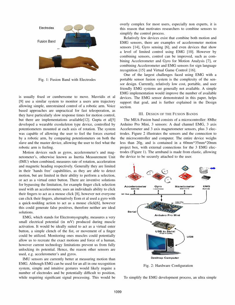
Fig. 1: Fusion Band with Electrodes
is usually fixed or cumbersome to move. Mavridis et al[9] use a similar system to monitor a users arm trajectoryallowing simple, unrestrained control of a robotic arm. Voicebased approaches are unpractical for fast teleoperation, asthey have particularly slow response times for motion control,but there are implementations available[12]. Gupta et al[5]developed a wearable exoskeleton type device, controlled bypotentiometers mounted at each axis of rotation. The systemwas capable of allowing the user to feel the forces exertedby a robotic arm, by comparing potentiometers on both theslave and the master device, allowing the user to feel what therobotic arm is feeling.
Motion devices such as gyros, accelerometer’s and mag-netometer’s, otherwise known as Inertia Measurement Unit(IMU) when combined, measures rate of rotation, accelerationand magnetic heading respectively. Generally they are limitedin their ’hands free’ capabilities, as they are able to detectmotion, but are limited in their ability to perform a selection,or act as a virtual enter button. There are inventive solutionsfor bypassing the limitation, for example finger click selectionused with an accelerometer, uses an individuals ability to clicktheir fingers to act as a mouse click [8], however not everyonecan click their fingers, alternatively Eom et al used a gyro witha quick-nodding action to act as a mouse click[6], howeverthis could generate false positives, therefore neither are idealsolutions.
EMG, which stands for Electromyography, measures a verysmall electrical potential (in mV) produced during muscleactivation. It would be ideally suited to act as a virtual enterbutton, a simple clench of the fist, or movement of a fingercould be utilized. Monitoring ones muscles could potentiallyallow us to recreate the exact motions and force of a human,however current technology limitations prevent us from fullyunlocking its potential. Hence, the reason other sensors areused, e.g. accelerometer’s and gyros.
IMU sensors are currently better at measuring motion thanEMG. Although EMG can be used for an all in one recognitionsystem, simple and intuitive gestures would likely require anumber of electrodes and be potentially difficult to position,while requiring significant signal processing. This would be
overly complex for most users, especially non experts, it isthis reason that motivates researchers to combine sensors tosimplify the control process.
Relatively few devices exist that combine both motion andEMG sensors, there are examples of accelerometer motionsensors [14], Gyro sensing [6], and even devices that showa level of limited control using EMG [10]. However bycombining sensors, control can be improved, such as com-bining Accelerometer and Gyro for Motion Analysis [7], orcombining Accelerometer and EMG sensors for sign languagerecognition [15] and Virtual Game Control [16].
One of the largest challenges faced using EMG with aportable sensor fusion system is the complexity of the sen-sor design. Currently, relatively low cost, portable, and userfriendly EMG systems are generally not available. A simpleEMG implementation would improve the number of availabledevices. The EMG sensor demonstrated in this paper, helpssupport that goal, and is further explained in the Designsection.
III. DESIGN OF THE FUSION BANDS
The MEA-Fusion band consists of a microcontroller: 8MhzArduino Pro Mini, 3 sensors: A dual channel EMG, 3 axisAccelerometer and 3 axis magnetometer sensors, plus 3 elec-trodes. Figure 2 illustrates the sensors and the connection tothe microcontroller and computer. The entire device weighsless than 20g, and is contained in a 60mm*35mm*20mmproject box, with external connections for the 3 EMG elec-trodes (Figure 1). The armband is made from elastic, allowingthe device to be securely attached to the user.
Fig. 2: Hardware Configuration
To simplify the EMG development process, an ultra simple

3 piece EMG circuit was constructed consisting of an INA128Instrumentation Amplifier (IA) and a capacitor. The additionof a rectifying diode performs half wave signal rectification.Further details on how the INA128 and capacitor interact toform the EMG circuit can be found in[1].
The EMG sensor requires 3 electrodes, a negative, positiveand ground. With the positive and negative electrodes placedadjacent to each other over the muscle determined for ’virtualenter button’ activation, and the ground electrode placed over abony area with minimal to no muscle activation. The electrodeswere 30mm in diameter, reusable, self-adhesive, and used inTENS, EMG and Neuromuscular stimulation applications.
The amplitude of the EMG signal over time is a goodindicator of muscle force, therefore a simple muscle clenchcombined with a moving average threshold can be used asthe virtual enter button. This approach is based on a similarapproach found in [4]. As each user will have different muscleforce to EMG amplitude ratios, a simple maximum voluntarycontraction calibration may be required for new users.
To measure the pitch, data from the accelerometer had to beutilized. Accelerometer’s measure acceleration, and are oftenused to measure roll and pitch, however they can only do soreliably when moving relatively slowly, otherwise accelerationdata effects the results. Most one axis accelerometer’s aresensitive up to 45 degrees where they then begin to loosesensitivity. Which is why more than one axis is normallyused. The angle can be calculated from two axis using atrigonometry equation: tan = sin / cos, which simply translatesto: tan( X / Y), where X and Y are the accelerometer’s rawX and Y values. For accurate measurements of pitch and yawall 3axis of an accelerometer should be used, this allows pitchto be compensated from roll data. This can be done using theatan2 function (arctan) with equation (1), where X, Y, and Zare the raw accelerometer values.
Pitch = atan2(X,√Y 2 + Z2) (1)
Substituting X for Y and Y for X returns the roll angle.However, the values may need to be changed depending on theorientation of the accelerometer. Which quadrant the value liesin is determined by analyzing the signs of the raw accelerome-ter data. The yaw is calculated from the magnetometer, whichcan detect magnetic fields (the same as an electronic compass),however when the magnetometer is inclined erroneous readingoccur. By incorporating the accelerometer pitch and roll, wecan compensate for errors by using equation (2) taken from[2] . X,Y and Z are the magnetometer readings after adjustingto a usable range using equation (3) . φ and θ representaccelerometer pitch and roll.
XH = Xcos(φ) + Y sin(θ)sin(φ)− Zcos(θ)sin(φ)Y H = Y cos(θ) + Zsin(θ)Y aw = atan2(−Y H/XH)
(2)
UsableRange =AxisMax−AxisMin
2(3)
The MEA-Fusion band uses the MAG3110 16 bit low-power, digital 3-axis magnetometer and the low power 14bit
BMA180 3-axis accelerometer, neither prohibitively expen-sive. The sensors communicate over a I2C link to a microcon-troller, while the EMG sensor is sampled from the Arduino’sonboard ADC. Data is transmitted from the microcontrollerserial port to the computer via the FTDI FT23RL USB to serialintegrated circuit. The use of an Arduino board simplifies andspeeds up the design process, allowing for faster developmenttimes. Although limited in its code efficiency, it provides anexcellent prototyping structure. The variety of sizes and speedsallows a tailor made design.
The GE-Fusion Band has been described previously in [1],with the only major differences to MEA-Fusion Band beingthe variation of sensors from magnetometer and acceleromter,to Gyro sensors, along with alternate signal processing.
IV. EXPERIMENTAL RESULTS
Two major components of teleoperation are sensing andcontrol applications. Remote sensors provide the informationas input into the control system, which directly manipulates arobot. The performance of the teleoperation can be evaluatedbased on accuracy, intuitiveness, and response time.
An experiment was designed which tests accuracy and speedto analyze how the GE and MEA Fusion bands compareagainst traditional teleoperation control techniques includingkeyboard input and joystick control.
Fig. 3: Edubot Robotic Arm Control Application
The experiment used an Edubot Robotic Arm, which hasfive degrees of freedom and a gripper. The gripper on theend of the robot allows the robotic arm to pick up smalllight weight objects. The Edubot arm was chosen for itsflexibility, light weight and fast response time. A SC-322servo controller containing an ATMEGA8 microcontroller wasused to interface the robotic arm to the computer. The devicegenerates pulse width modulation (PWM) square waves tocontrol servo motors.
In the experiment we used two joints of the robotic armfor yaw and pitch, as shown in figure 3. The first joint fixedto the table produces yaw action by rotating the robot. Thesecond joint connects to the first joint and provides the pitch,allowing the robot to go down to pick up objects. The last partis a two-state gripping device formed by two fingers. This is
controlled from the muscle signal, and used to either close (tograb) or open (to release) the gripper.
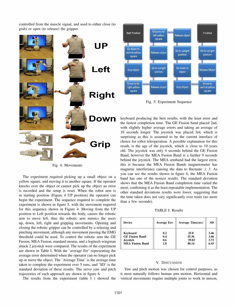
Fig. 4: Movements
The experiment required picking up a small object on ayellow square, and moving it to another square. If the operatorknocks over the object or cannot pick up the object an erroris recorded and the setup is reset. When the robot arm isin starting position (Figure 4 UP position) the operator canbegin the experiment. The sequence required to complete theexperiment is shown in figure 5, with the movement requiredfor this sequence shown in Figure 4. Moving from the UPposition to Left position towards the body, causes the roboticarm to move left, thus the robotic arm mimics the usersup, down, left, right and gripping movements. Opening andclosing the robotic gripper can be controlled by a relaxing andpinching movement, although any movement passing the EMGthreshold could be used. To control the robotic arm the GEFusion, MEA Fusion, standard mouse, and a logitech wingmanattack 2 joystick were compared. The results of the experimentare shown in Table I. With the ’average Err’ representing theaverage error determined when the operator can no longer pickup or move the object. The ’Average Time’ is the average timetaken to complete the experiment over 5 runs, and ’SD’ is thestandard deviation of these results. The servo yaw and pitchtrajectories of each approach are shown in figure 6.
The results from the experiment (table I ) showed the
Fig. 5: Experiment Sequence
keyboard producing the best results, with the least error andthe fastest completion time. The GE Fusion band placed 2nd,with slightly higher average errors and taking an average of10 seconds longer. The joystick was placed 3rd, which issurprising as this is assumed to be the current interface ofchoice for robot teleoperation. A possible explanation for thisresult, is the age of the joystick, which is close to 10 yearsold. The joystick was only 4 seconds behind the GE FusionBand, however the MEA Fusion Band is a further 9 secondsbehind the joystick. The MEA armband had the largest error,this is because the MEA Fusion Bands magnetometer hasmagnetic interference causing the data to fluctuate ± 3. Asyou can see the results shown in figure 6, the MEA Fusionband has one of the nosiest results. The standard deviationshows that the MEA Fusion Band completion time varied themost, confirming it as the least repeatable implementation. Theother standard deviations results were lower, suggesting thatthe time taken does not vary significantly over trials (no morethan a few seconds).
TABLE I: Results
Device Average Err. Average Time(sec) SD
Keyboard 0.2 25.8 3.46GE Fusion Band 0.4 35.36 3.46Joystick 0.6 39.03 3.72MEA Fusion Band 1.8 48.14 6.43
V. DISCUSSION
Yaw and pitch motion was chosen for control purposes, asit most naturally follows human arm motion. Horizontal andvertical movements require multiple joints to work in unison,

Fig. 6: Yaw and Pitch Servo Movement Graphs for Keyboard,Joystick, MEA and GE Fusion Bands
thus requiring additional energy expenditure. Using pitch andyaw employs well developed muscles used in everyday life,thus minimizes muscle fatigue, allowing a the operator to usethe Fusion Band for longer periods.
There are certain limitations with using EMG on the wrist,for one, rotation of the wrist will effect the EMG signalcausing a false positive, thus this is the reason yaw and pitchare used. Smaller, more selective electrodes would improve
the interaction, plus machine learning might be able to extractfurther usable information. Roll could potentially be useableat other locations on the arm, where muscles not linked withroll activity are present.
The Fusion Band results compared reasonably well againstthe standard Keyboard and Joysticks implementations, as canbe seen from table I. Work still needs to be done on improvingthe gyro drift, and magnetometer interference, as these causethe majority of the erroneous results.
The robotic arm has 180 degrees of yaw, however com-fortable arm movement in a stationary position is half that.This gives effective control of 1 Fusion Band degree to 2robotic arm degrees. Thus it can be logically deduced thatreducing the applications range of movement to a smallercontrol area, would improve the accuracy of the interfacesand likely improve experimentation results.
The Majority of the Fusion Bands processing is performedon the microcontroller, this includes the acquisition, and partialprocessing(using equations 1,2,3). The receiving device onlyperforms moving average functionality. This frees up thereceiving device’s processing time, potentially allowing it towork with a larger proportion of devices (Portable and fixed).The fusion band has the majority of hardware enclosed in asmall area, even the electrodes can be worn underneath thearmband, making the interface relatively small and easy touse, even for non-experts.
Fig. 7: Fusion Band Freedom of Motion
To use the Fusion Band a portion of the arm must bymovable in the yaw and pitch orientations i.e. up/down andleft/right around a central point (As shown in figure 7). Anymuscle adjacent to the Fusion Band can be used to generatean EMG signal to control the virtual enter button, therefor thisdevices is not suitable for paralyzed individuals.
Originally when the GE Fusion Band was developed, it hadan inherent limitation, over time the readings would drift. Thiswas caused from not reading the gyro’s rate of rotation inevery moment in time i.e. rotation occurs between readings,which you cannot record. Faster readings do reduce drift,but does not remove it. There are situations where the driftcan be ignored, for example, motion activation only duringuser activated EMG, would allow the user to automaticallycompensate for drift. However this may limit the virtual

enter button capabilities. An alternative device (the MEAFusion Band) was built using sensors with absolute position-ing (magnetometer and accelerometer). However it was notwithout its problems, the magnetometer can be influencedby electromagnetic interference, and ferrous materials. Thiscan cause the magnetometer to reduce sensitivity and producedead areas, where abnormal measurements occur. Hence themagnetometer was kept away from the main circuitry. Anaccelerometer is originally used to measure acceleration, butcan also measure absolute pitch due to gravitational effecton the accelerometer Z axis. Even though the pitch can becalculated, sudden and quick movements cause accelerationto infiltrate the pitch readings.
The low number of experiment iterations were performedto analyze the Fusion Band’s potential, further repeatabilityexperiments should take place to confirm the safety and use-ability for long term applications. The previously mentionedFusion Band limitations may also suggest that an improvedarmband could be developed.
The Fusion Band prototype, was designed from ’off theshelf’ parts. The Arduino Pro mini is limited in processingpower and code efficiency, however it makes up for these lim-itations with its small ’footprint’, and ease of use. Attemptingto use further sensors to improve the device, or includingcomplex signal processing, is likely to need an improvedmicrocontroller.
The Fusion Bands can jump the gap from a robotic armcontroller, to a general user interface. This uniqueness comesfrom being able to use the device on or off a table, or whenstanding or sitting. It is light weight, easily portable, and caninterface with any device that requires human interaction. AFusion Band could completely change the way we interactwith industrial machines and robots, providing an easy to useand intuitive interface to users. Applications could includebut are not limited to, control of mobile phone, control of acomputer mouse, 3d object manipulation, virtual reality, robotcontrol, robotic arm control, virtual witting, virtual signatureused for passwords or document signing, simple TV remotecontrol, rehabilitation, and games console controllers.
VI. CONCLUSION AND FUTURE WORK
Conventional Human Computer Interaction technologiesbased on mouse and keyboard do not meet the needs fornaturally interfacing with computers for disabled or non-disabled users, thus alternatives must be found. This paperpresents a intuitively controlled sensor fusion armband thatconsists of a magnetometer, accelerometer for motion control,and an ultra simple EMG circuit for virtual enter buttonfunctionality. The MEA Fusion Band, along with a gyro basedapproach (GE Fusion Band) were compared against otherteleoperating devices for controlling a robotic arm and gripper.The results found the keyboard had the most accurate andfastest results in a seated environment followed by the GEFusion, Joystick and MEA Fusion approaches. However thefusion bands show promise in instances where a portableinterface with similar human motion capture is required. The
Fusion Bands are ideally suited to work with small devices,where a physical user interface is difficult to implement,for example: interfacing with a wearable visor/glasses baseddisplay. The Fusion Bands aim to make interaction moreintuitive for users, and provides an alternative method forcontrolling robotic arms.
Future research involves making the device entirely wire-less. While potentially including additional features such asvoice recognition, to enhance interaction. Adding an alter-native to vision based feedback could further enhance userinteraction. The addition of further EMG channels wouldincrease the number of potential applications, as shown in[15]. When combined with motion sensor fusion, a rich userinterface to control devices could be realized.
ACKNOWLEDGMENTS
This research has been financially supported by the EPSRCgrant - ”Global Engagement with NASA JPL and ESA inRobotics, Brain Computer Interfaces, and Secure AdaptiveSystems for Space Applications - RoBoSAS”, EP/K004638/1.The 1st author is financially supported by EPSRC StudentshipEP/P504910/1. We would also like to thank Robin Dowlingfor the technical support.
REFERENCES
[1] James A R Cannan and Huosheng Hu. A wearable sensor fusionarmband for simple motion control and selection for disabled and non-disabled users. 2012.
[2] Michael J. Caruso. Applications of magnetoresistive sensors in naviga-tion systems. Unknown Year.
[3] Dan Morris Chris Harrison, Desney Tan. Skinput: Appropriating thebody as an input surface. 2010.
[4] Rebecca Allen Pattie Maes. Enrico Costanza, Samuel A. Inverso. Inti-mate interfaces in action: assessing the usability and subtlety of emg-based motionless gestures. pages 819–828, 2007.
[5] C. H. Messom G. Sen Gupta, S.C. Mukhopadhyay and S. Demidenko.Master-slave control of a teleoperated anthropomorphic robotic arm withgripping force sensing. 2006.
[6] Chul-Seung Kim-James Lee Soon-Cheol Chung-Bongsoo Lee Hi-roki Higa Norio Furuse Ryoko Futami Takashi Watanabe. Gwang-Moon Eom, Kyeong-Seop Kim. Gyro-mouse for the disabled: clickand position control of the mouse cursor. 2007.
[7] Rene Winkler Johannes Schumm Martin Kusserow Holger Harms,Oliver Amft and Gerhard Troester. Ethos: Miniature orientation sensorfor wearable human motion analysis. 2010.
[8] Libo He Jack Toole, Aaron King. Chronos flying mouse -http://processors.wiki.ti.com/index.php/chronos-flying-mouse. 2011.
[9] Giakoumidis N. Batalas N. Shebli I. Ameri E.-Neyadi F.-Neyadi A.Mavridis N., Machado E. Real-time teleoperation of an industrial roboticarm through human arm movement imitation. 2010.
[10] Kostas J. Kyriakopoulos Panagiotis K. Artemiadis. Estimating armmotion and force using emg signals: On the control of exoskeletons.2008.
[11] Pattie Maes Pranav Mistry and Liyan Chang. Wuw - wear ur world - awearable gestural interface. 2009.
[12] P. J. Sanz A. Marzal R. Marin, P. Vila. Automatic speech recognitionto teleoperate a robot via web. 2002.
[13] Vicon. Vicon motion capture system. - www.vicon.com/. 2012.[14] Xiang Zhang Weidong Geng Xiubo Liang, Shun Zhang. Motion-based
perceptual user interface. 2009.[15] Jianxun Tian Xu Zhang Kongqiao Wang Jihai Yang Yun Li, Xiang Chen.
Automatic recognition of sign language subwords based on portableaccelerometer and emg sensors. 2010.
[16] Wang Wen-hui Yang Ji-hai Vuokko Lantz-Wang Kong-qiao Zhang Xu,Chen Xiang. Hand gesture recognition and virtual game control basedon 3d accelerometer and emg sensors. 2009.