
A modular approach to file system design · PDF fileA modular approach to file system design *...
14
A modular approach to file system design * by STUART E. }IADNICK M a8sachusetts Institute of Technology Cambridge. Massachusetts and JOSEPH W. ALSOP, II International Computation Incorporated Cambridge, Massachusetts IXTRODUCTIOK A generalized model or "blue-print" for the design of sophisticated file systems is presented in this paper. The model exploits the concepts of "hierarchical modularity" and "virtual memory." Any general file system design model must, of course, be modified and refined to satisfy the requirements of a specific environment. The details of the file system model are presented in three steps: (1) the basic concepts and overview are discussed, (2) an example environment consisting of a multi-computer network with the added complexities of coordination, structured file directories, and removable volumes is described , and (3) each of the hierarchical levels of the file system is elaborated in terms of the assumed environment. Basic concepts used in file system design Two concepts are basic to the general file system model to be introduced. These concepts have been described by the terms "hierarchical modularity" and "virtual memory." They will be discussed briefly below. Hierarchical modularity The term "modularity" means many different things to different people. In the context of this paper we * Work reported herein was suppOlted (in part) by Project MAC, an M.LT. research project sponsored bv the Advanced Research Projects Agency, Department of "DefeI.se. under Office of Xaval Research Contract Xonr-4102(Ol). will be concerned with an organization similar to that proposed by Dijkstra 6 ,7, and Randell. 14 The important aspect of this organization is that all activities are divided into sequential processes. A hierarchical structure of these sequential processes results in a level or ring organization wherein each level only communi- cates with its immediately superior and inferior levels. The notions of "levels of abstraction" or "hier- archical modularity" can best be presented briefly by an examp Ie. Consider an aeronautical engineer using a matrix inversion package to solve space flight prob lems . At his level of abstraction, the computer is viewed as a matrix inverter that accepts the matrix and control information as input and provides the inverted matrix as output. The application programmer who wrote the matrix inversion package need not have had any knowledge of its intended usage (superior levels of abstraction). He might view the computer as a "FOR- TRAN" machine", for example, at his level of ab- straction. He need not have any specific knowledge of the internal operation of the FORTRAN system (inferior level of abstraction), but only of the way in which he can interact with it. Finally, the FORTRAK compiler implementer operates at a different (lower) level of abstraction. In the above example the inter- action between the 3 levels of abstraction is static since after the matrix inversion program is completed, the engineer need not interact, even indirectly, with the applications programmer or compiler implementer. In the form of hierarchical modularity used in the file system design model, the multi-level interaction IS continual and basic to the file system operation. From the collection of the Computer History Museum (www.computerhistory.org)
Transcript of A modular approach to file system design · PDF fileA modular approach to file system design *...

A modular approach to file system design *
by STUART E. }IADNICK
M a8sachusetts Institute of Technology Cambridge. Massachusetts
and
JOSEPH W. ALSOP, II
International Computation Incorporated Cambridge, Massachusetts
IXTRODUCTIOK
A generalized model or "blue-print" for the design of sophisticated file systems is presented in this paper. The model exploits the concepts of "hierarchical modularity" and "virtual memory."
Any general file system design model must, of course, be modified and refined to satisfy the requirements of a specific environment. The details of the file system model are presented in three steps: (1) the basic concepts and overview are discussed, (2) an example environment consisting of a multi-computer network with the added complexities of coordination, structured file directories, and removable volumes is described , and (3) each of the hierarchical levels of the file system is elaborated in terms of the assumed environment.
Basic concepts used in file system design
Two concepts are basic to the general file system model to be introduced. These concepts have been described by the terms "hierarchical modularity" and "virtual memory." They will be discussed briefly below.
Hierarchical modularity
The term "modularity" means many different things to different people. In the context of this paper we
* Work reported herein was suppOlted (in part) by Project MAC, an M.LT. research project sponsored bv the Advanced Research Projects Agency, Department of "DefeI.se. under Office of Xaval Research Contract Xonr-4102(Ol).
will be concerned with an organization similar to that proposed by Dijkstra6 ,7, and Randell.14 The important aspect of this organization is that all activities are divided into sequential processes. A hierarchical structure of these sequential processes results in a level or ring organization wherein each level only communicates with its immediately superior and inferior levels.
The notions of "levels of abstraction" or "hierarchical modularity" can best be presented briefly by an examp Ie. Consider an aeronautical engineer using a matrix inversion package to solve space flight prob lems . At his level of abstraction, the computer is viewed as a matrix inverter that accepts the matrix and control information as input and provides the inverted matrix as output. The application programmer who wrote the matrix inversion package need not have had any knowledge of its intended usage (superior levels of abstraction). He might view the computer as a "FORTRAN" machine", for example, at his level of abstraction. He need not have any specific knowledge of the internal operation of the FORTRAN system (inferior level of abstraction), but only of the way in which he can interact with it. Finally, the FORTRAK compiler implementer operates at a different (lower) level of abstraction. In the above example the interaction between the 3 levels of abstraction is static since after the matrix inversion program is completed, the engineer need not interact, even indirectly, with the applications programmer or compiler implementer. In the form of hierarchical modularity used in the file system design model, the multi-level interaction IS
continual and basic to the file system operation.
From the collection of the Computer History Museum (www.computerhistory.org)

2 Spring Joint Computer Conference, 1969
Figure I-Hierarchical levels
There are several advantages to such a modular organization. Possibly the most important is the logical completeness of each level. It is easier for the system designers and implementers to understand the functions and interactions of each level and thus the entire system. This is often a very difficult problem in very complex file systems with tens or hundreds of thousands of instructions and hundreds of interdependent routines.
Another by-product of this structure is "debugging" assistance. For example, when an error occurs it can usually be localized at a level and identified easily. The complete verification (reliability checkout) of a file system is usually an impossible task since it would require tests using all possible data input and system requests. In order to construct a finite set of relevant tests, it is necessary to consider the internal structure of the mechanism to be tested. Therefore, an important goal is to design the internal structure so that at each level, the number of test cases is sufficiently small that they can all be tried without overlooking a situation. In practice, level ° would be checked out and verified, then levell, level 2, etc., each level being more powerful, but because of the abstractions introduced, the number of "special cases" remains within bounds.
Virtual memory
There are four very important and difficult file system objectives: (1) a flexible and versatile format, (2) as much of the mechanism as possible should be invisible, (3) a degree of machine and device independence, and (4) dynamic and automatic allocation of secondary storage. There have been several techniques developed
to satisfy these objectives in an organized manner; the concept exploited in this generalized file system has been called "segmentation"5 or "named virtual memorv" . 3 Under this system each file is treated as an ~rdered sequence of addressable elements, where each element is normally the same size unit as the main storage, a byte or word. Therefore, each individual file has the form of a "virtual" core memory, from whence the name of the technique came. The size of each file is allowed to be arbitrary and can dynamically grow and shrink. There is no explicit data format associated with the file; the basic operations of the file system move a specified number of elements between designated addresses in "real" memory and the "virtual" memory of the file system.
There are several reasons for choosing such a file concept. In some systems the similarity between files and main storage is used to establish a single mechanism that serves as both a file system for static data and program storage and a paging system3,5,8 for dynamic storage management. "Virtual memory" provides a very flexible and versatile format. When specific formatting is desired, it can be accomplished by the outermost file system level or by the user program. For example, if a file is to be treated as a collection of card-image records, it is merely necessary to establish a routine to access 80 characters at a time starting at byte locations 0,80, 160, .... Almost all other possible formats can be realized by similar procedures.
Except for the formatting modules, the entire file system mechanism, including allocations, buffering, and physical location, is completely hidden and invisible to the user. This relates closely to the objective of device independence. In many file systems the user must specify which device should be used, its record size' (if it is a hardware formatable device), blocking and buffering factors, and sometimes even the physical addresses. Although the parameters and algorithms chosen might, in some sense, be optimal, many changes might be necessary if the program is required to run with a different configuration or environment.
There are very serious questions of efficiency raised by this file system strategy. lHost of these fears can be eased by the following considerations. First, if a file is to be used very seldom as in program development, efficiency is not of paramount importance; if, on the other hand, it is for long-ternl use as in a commercial production program, the device-independence and flexibility for change and upkeep will be very important. Second, by relieving the programmer of the complexities of the formats, devices, and allocations, he is able to utilize his energy more constructively and creatively to develop clever algorithms relating to the
From the collection of the Computer History Museum (www.computerhistory.org)

r------l I I I I I I I I I I I I I I I I
/~
/~ I I I I I I I I I I I I
READ I I FROM L ____ :_;
FILE "9" FILE 9
MAIN STORAGE
Figure 2-"Real" memory and "virtual" file memory
logical structuring of his problem rather than clever "tricks" to overcome the shortcomings or peculiarities of the file system. Third, in view of· the complexity of current direct-access devices, it is quite possible that the file system will be better able to coordinate the files than the average user attempting to specify critical parameters.
Overview of file system design model
The file system design model to be presented in this paper can be viewed as a hierarchy of six levels. _ In a specific implementation certain levels may be further sub-divided or combined as required. A ,recent study of several modern file systems, which will be published in a separate report, attempts to analyze the systems in the framework of this basic model. In general all of the systems studied fit into the model, although certain leveh; in the model are occasionally reduced to trivial fonn or are incorporated into other parts of the operating systenl.
The six hierarchical levels are:
1. Input/Output Control System (IOCS) 2. Device Strategy )Iodules (DS)I) :3. File Organization Strategy }Iodules (FOS)!) 4. Basic File System (BPS) 5. Logical File System (LFS) 6. Access :\Iethods and User Interface
The hierarchical organization can be described from the "top" dO\vn or from the "bottom" up. The file system would ordinarily be implemented by starting at the lowest level, the Input/Output Control System, and working up. It appears more meaningful, however,
:Modular Approach to File System Design 3
to present the file system organization starting at the most abstract level, the access routines, and removing the abstractions as the levels are "peeled away';.
In the following presentation the terms "file name", "file identifier", and "file descriptor" will be introduced. Detailed explanations cannot be provided until later sections, the following analogy may be used for the reader's assistance. A person's name (file name), due to the somewhat haphazard process of assignment, is not necessarily unique or manageable for computer processing. A unique identifier (file identifier) is usually aSf-'ligned to each person, such as a Social Security number. This identifier can then be used to locate efficiently the information (file descriptor) known about that person.
Access Methods (AM)
This level consists of the set of routines that superimpose a format on the file. In general there will probably be routines to simulate sequential fixed-
Level 6: Access Methods (AM) User Interfaces
Level 5: Logical File System (LFS)
Level 4: Basic File System (BFS)
Level 3: File Organization Strategy Modules (FOSM)
Level 2: Device Strategy Modules (DSM)
Level I: Input/Output Control System (IOCS)
Devices
Figure :3-Hiel'al'chical file systems
From the collection of the Computer History Museum (www.computerhistory.org)
4 Spring Joint Computer Conference, 1969
length record files, sequential variable-length record files, and direct-access fixed-length record files, for example. lVlany more elaborate and specialized fonnat routLTleS, also called access methods or d9Jta management, can be supplied as part of the file system. Obviously, a user may write his own access methods to augment this level.
Logical File System (LFS)
Routines above this level of abstraction associate a symbolic name with a file. It is the function of the Logical File System to use the symbolic file name to find the corresponding unique "file identifier". Below this level the symbolic file name abstraction is eliminated.
Table I-Example procedure to perform logical file system search
-;. VOLUrlE CdAidIC'l'E.! (&1,
)0 • - 1 TC l?A'fi;_LE~';TrI;
J~ J = ,} rlY ;i ".:,li"' {FIL,":_-,->:,":;L>:r.F;A"H .,: P,\"':I(Il);
Basic File System (BFS)
The Basic File System must convert the file identifier into a file descriptor. In an abstract sense, the file descriptor provides all infonnation needed to physically locate the file, such as the "length" and "location" of the file. The file descriptor is also used to verify access rights (read-only, write-only, etc.), check read! write interlocks, and set up system -wide data bases. The Basic File System perfonns ~any of the functions ordinarily associated with "opening" or "closing" a file. Finally, based upon the file descriptor, the appropriate FOSlVI for the file is selected.
File Organization Strategy Modules (FOSM)
Direct-access devices physically do not resemble a virtual memory. A file must be split into many separate
~-------11--n Record 4
}. ' '. DRecord7
} -- D Record 14
c __ nn_1 } · · D Record 2
File Virtual PhysiCO! Records Memory
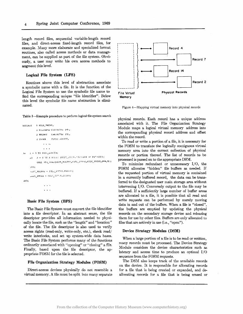
Figure 4---l\1:apping v"irtual memory' into ph:ysical records
physical records. Each record has a unique address associated with it. The File Organization Strategy Module maps a logical virtual memory address into the corresponding physical record address and offset within the record.
To read or write a portion of a file, it is necessary for the FOSM to translate the logically contiguous virtual memory area into the correct collection of physical records or portion thereof. The list of records to be processed is passed on to the appropriate DSM.
To minimize redundant or unnecessary I/O, the FOSM allocates "hidden" file buffers as needed. If the requested portion of virtual memory is contained in a currently buffered record, the data can be transferred to the designated user main storage area without intervening I/O. Conversely output to the file may be buffered. If a sufficiently large number of buffer areas are allocated to a file, it is possible that all read and write re.quests can be perfonned by merely moving data in and out of the buffers. When a file is "closed", the buffers are emptied by updating the physical records on the secondary storage device and releasing them for use by other files. Buffers are only allocated to files that are actively in use (Le., "open").
Device Strategy Modules (DSM)
When a large portion of a file is to be read or written, many records must be processed. The Device Strategy Module considers the device characteristics such as latency and access time to produce an optimal I/O sequence from the FOSM requests.
The DSM also keeps track of the available records on the device. It is responsible for allocating records for a file that is being created or expanded, and deallocating records for a file that is being erased or
From the collection of the Computer History Museum (www.computerhistory.org)

truncated. The FOS}! requests that a record be allocated when needed, the DS::\! selects the record.
Input/Output Control System (IOCS)
The Input/Output Control System coordinates all physical I/O on the computer. Status of all outstanding I/O in process is maintained, new I/O requests are issued directly if the device and channel are available; otherwise the request is que"!led and automatically issued as soon as possible. Automatic error recovery is attempted when possible. Interrupts from devices and unrecoverable error conditions are directed to the appropriate routine. Almost all modern operating systems have an laCS.
File systems versus data management systems
In the literature there is often confusion between systems as described above, "\vhich this paper calls "file systems" and systems which will be called "data management systems", such as Dl\I-1,8 GIM-1,13 and TD::\IS.17 The confusion is to be expected since both types of systems contain all of the functional levels described above. The systems differ primarily on the emphasis placed on certain levels.
In general file systems, the file is considered the most important item and emphasis is placed on the directory organization (Logical File System) and the lower hierarchical levels. It is expected that specialized access methods will be written by users or supplied with the system as needed.
In most data management systems, the individual data items are considered the most important aspect, therefore emphasis is placed on elaborate access methods with minimal emphasis on the lower levels of abstraction. Because of the heavy emphasis on a single level, data management systems tend to appear less hierarchical than file systems since the lower levels are often absorbed into the access methods.
~~.1 ulti-computer -netwurk e;nvitO'tI/rneni
A general file system design model must, of course, be modified and elaborated to satisfy the needs of any specific desired file system environment. To illustrate the refinement process, a unique file system design will be presented for a multi-computer network.
Multi-computer networks are becoming an increasingly important area of computer technologyY There are several significant reasons behind the growth of multi-computer networks:
1. To increase the power of a computer installation in a modular manner, especially if (a) it
Modular Approach to File System Design 5
is not possible to acquire a larger processor, (b) reliability is important, or (c) there are real-time or time-sharing constraints.
2. To serve the coordination requirements of a network of regional computer centers.
3. To support the accessibility to a nation-wide data base.
An example of the envl...rornnent to be considered. for this paper can be illustrated in Figure 5. This type of multi-computer network has been in limited use for several years in many configurations. The IBM 7094/7044 Direct-Coupled System was probably one of the earliest practical examples of such an interconnected arrangement.
There are several implicit constraints imposed upon the multi-computer system illustated in Figure 5:
1. Independence of Central Processors. Each of the central processors operates independently such that there are no direct processorto-processor data transfer nor signaling, and furthermore there is no "master" processor.
2. Non-shared YIemory. Each central processor has its own main storage unit. These units are not shared with nor accessed by another central processor.
3. Inter-locked Device Controllers. The device controllers act as "traffic cops" to the actual I/O direct access devices. They control the traffic between a computer's I/O channel and a selected I/O device. A single device controller will only accept requests from one channel at a time and will only select one I/O device (among those under its control) at a time. Once a device controller connects a.
CPU CPU CPU ---------- --------- ---------MEMORY MEMORY MEMORY ---------- ---------- --- -------CHANNELS CHANNELS CHANNELS
Figure 5-Example of multi-computer file system network
From the collection of the Computer History Museum (www.computerhistory.org)
6 Spring Joint Computer Conference, 1969
channel with a device, the connection lemains intact until the channel releases the device or an I/O error occurs,
The environment described above, although well within the boundaries of current technology, has not been the subject of much investigation. Such configurations are presently very expensive and, therefore, chosen only for very specialized situations. Even then there are only two or three processors and very specialized software and operational factors. A discussion of the CP-67/CMS Time Sharing System 9,21 will serve to establish the relevance of the multicomputer network environment.
The CP-67/CMS Time Sharing System uses the special hardware features of a single IBNI System/360 model 67 processor augmented by software to produce an apparent environment corresponding to the multicomputer network illustrated in Figure 5, with many independent central processors, device controllers, and direct access I/O devices. In practice a typical single processor 360/67 configuration w{)uld produce the affect of about 30 active processors ("vii'tual" System/ 360 model 65 processors each with a 256,000 byte memory) and 50 active device controllers. ~10re
detailed descriptions of the CP-67/CMS System can be found in the References. 1:n the traditional sense of time-sharing, each user of the CP-67/CMS System is provided with a "virtual" computer operated from a simulated operator console (actually an augmented remote terminal). Most importantly, each "virtual" computer (i.e., user) operates logically independently of all other" virtual" computers except for the specified inter-connected I/O devices and device controllers.
Problems arising in multi-computer networks
There are many problems associated with the multicomputer file system network. Some of these problems are unique to this environment. Other problems have been solved in traditional file systems,2,17,20 but the solutions require major revisions due to the peculiarities of the environment. The most significant problems are listed briefly below.
1. No shared memory. Usually file systems coordinate the status of the files and devices by using main storage accessible tables and data areas that describe file status, access rights, interlocks, and allocation. There is no such common communication area in main storage that can be accessed by all the independent processors.
2, NQ inter-computer communication. ~1ulti-computer configurations usually provide
a mechanjsm for sending signals or data transfers between the separate processors. With this capability the non-shared memory problem could be solved by either (a) electing one processor to be the "master" processor that coordinates the other processors, or (b) supply all the processors with enough information such that each processor knows what all the other processors are doing. The concept of a "master" processor opposes the intended homogeneous, independent processor assumption. The possibility of supplying status information to all other processors, although reasonable for a three or four processor configuration, was not considered a feasible solution for a system with hundreds of processors and devices and thouS'tands of files. For these reasons inter-, computer communication, although an available capability, was not included as a required capability of the multi-computer environment described above.
3. No pre-arranged allocations. For small specialized multi-computer file networks, each processor can be "assigned" a specific area of a device or set of devices that can be used to write new files, all other processors can only read from this area by convention. This prevents the danger of two independent processors writing files at the same place. Such an "arrangement" is not practical for a large, flexible multi-computer file network since the static assignment of secondary storage space does not take account of the dynamic and unpredictable requirements of the independent processors.
4. Extendable device and file allocation. The number of devices and sizes of devices as well as the number and sizes of files are, within reason, unlimited. For example, a specific amount of secondary storage equivalent to 100,000 card images could be used to hold 10 files of 10,000 cards each or 1,000 files of 100 cards each. This consideration discourages techniques that result in a strong efficiency or main storage capacity dependency on the" size and shape" of the file system. Of course, the magnitude of the file system size will affect the operation, but arbitrary restrictions such as "no more than 64 files on a device" would be discouraged unless essential.
5. R.emovable volumes. It has become common to differentiate between the I/O mechanism used to record or read information, called a "device", and the physical
From the collection of the Computer History Museum (www.computerhistory.org)

medium on which the information is stored, called a "volume". For most drums and many disk units, the device and volume are inseparable. But, for magnetic tape units and many of the smaller disk units the volume, magnetic tape reel and disk pack respectively, are removable. It is intended that the file system include files that are on unmounted volumes (discoY'.Jlected from an I/O device) as well as mounted volumes. Therefore, a configuration that consists of ten disk units may have a file system that encompasses hundreds of volumes, only ten of which may be actively in use at a time. Since removing and mounting a volume takes several minutes of manual effort, it will be assumed that the "working set" of volumes (volumes that contain files that are ~ctively in use) remains static for reasonable periods of time and is less than or equal to the number of devices available. The fact that volumes are removable and interchangeable (i.e., may be mounted on different devices at different times) does affect the organization of the file ~stem. For example, a scheme that involved. )i,nking files together by means of pointers . (Cihained addressing) could require mounting volumes just to continue the path of the chain even though little or no "logical" information was requested from files on that volume. In the worst case, it might· be necessary to mount and unmount all the volumes of the file system to locate a desired file. Such a situation should definitely be avoided if not totally eliminated by the file system.
6. Structured file directories and file sharing. In a traditional file system, the mapping between· the symbolic file name and the corresponding file was accomplished by means of a single )laster File Directory. For modern file systems with thousands of files scattered over hundreds of volfu"'1l6s, it became desirable, ii not necessary, to form groupings of files by means of Secondary File Directories.4 These groupings are often used by the system to associate users with files they own (User File Directories). This capability is also available to the user to arrange his files into further sub-groups (libraries) or into separate project-related groupings. Occasionally it becomes necessary for a file to be included in two or more groupings (e.g., accessible by more than one User File Directory) with potentially different access privileges (protection) associated with each grouping. l\Iany of these features
Modular Approach to File System Design 7
that are relatively easy to implement in a traditional file system are complicated by the introduction of independent processors and removable volume~.
7. Fail-safe operation. Reliable operation is a very important requirement of a general purpose file system. There are many known techniques for I/O error and systematic backup and salvage procedures that are applicable to this environment. The important problem associated with the multicomputer network is that potential error conditions exist that are not normally found ill traditional single computer file systems. For a single computer system, a processor error (including unexpected processor disconnection, i.e., "turning off") is a rare occurrence. Such a situation is remedied by repairing whatever physical hardware is necessary and then running a special "salvager" program to bring the file system into a well-defined operational state. In the environment of a multi-computer network, processors may be connected or disconnected at any time without any awareness by the other processors. To prevent any inconsistent file system operation by the other processors and eliminate the need for usually time-consuming salvage techniques, it is necessary to keep the file system in a well-defined consistent state at all times.
A file system design
The purpose of the remainder of this paper is to apply the organization presented in th, File System Design IHodel section to solve the problems associated with a multi-computer file system network. Discussion of the Access ::\Iethods and Input/Output Control System will be omitted. This is necessitated for brevity and consideration of the facts that the Access )Iethods are highly application oriented, as discussed in a previous section, and that the Input/Output Control System is usually a basic and common component of all Operating Systems. The principal contribution of this model lies in the structure of the four other levels.
Logical file system
To present the goals and requirements of the Logical File System in a brief and demonstrative manner, an example will be used. The reader should refer to Figure 6 for the following discussion. It is important that the peculiarities of the example, such as the choice of file names (e.g., "FILE6" and "DIR4"), not
From the collection of the Computer History Museum (www.computerhistory.org)
8 Spring Joint Computer Conference, 1969
VOLUME "Val I" VOLUME "VOl2"
(User 1)
Vall (3)
F1LE.3
D1R 2
Vall (2)
I111111111I
t VOll(6)
11/11111111
VOL 1(4)
111111/1111
VOL 1(5)
111/1/11111
(User 2)
VOl2(3)
DIR 3
FILE 5
FILE 6
VOL 2 (4)
I111111111I
VOLUME "VOL 3 "
(User 3)
VOL 3 (2)
D1R 4
DIR 3
VOL3(3)
11/1/111111
Figu!'e 6-Example of file directol'Y structure (to LFS)
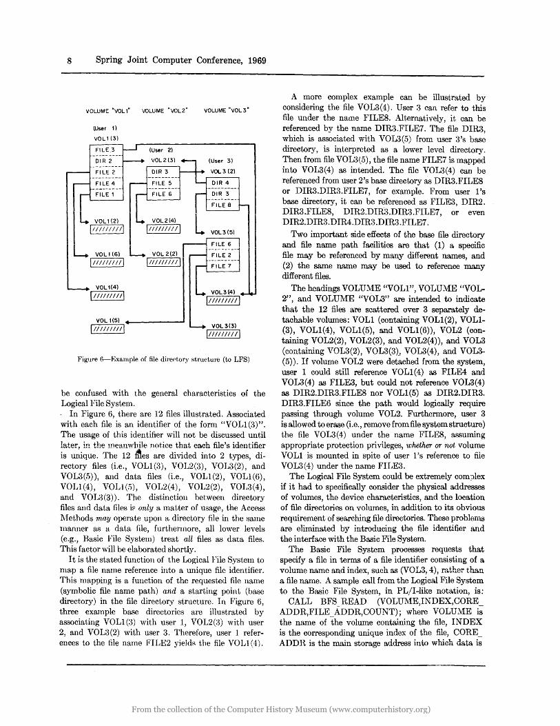
be confused with the general characteristics of the Logical File System. . In Figure 6, there are 12 files illustrated. Associated with each file is an identifier of the fomi "VOL1(3)". The usage of this identifier will not be discussed until later, in the meanwhile not.ice that each file's identifier is unique. The 12 lftes are divided into 2 types, directory files (i.e., VOL1(3), VOL2(3), VOL3(2) , and VOL3(b»), and data files (i.e., VOL1(2), VOL1(6), VOLl (4), VOLt U5), VOL2(4), VOL2(2), VOL3(4), and VOI~1(3». The distinction between directory files and data files i~ only a matter of usage, the Access lVrethods may operate upon a directory file in the same manner as a data file, furthermore, all lower levels (e.g., Basic File System) treat all files as data files. This factor vdll be elaborated shortly.
I t is the stated function of the Logical File System to map a file name reference into a unique file identifier. This mapping is a function of the requested file name (symbolic file name path) and a starting point (base directory) in the file directory structure. In Figure 6, three example base directories are illustrated by associating VOL1 (3) with user 1, VOL2U~) with user 2, and VOL3(2) with user 3. Therefore, user 1 references to the file name FILE2 yieldR the file VOLl (4).
A more complex example can be illustrated by considering the file VOL3(4). User 3 can refer to this file under the name FILE8. Alternatively, it can be referenced by the name DIR3.FILE7. The file DIRa, which is associated with VOL3(5) from user 3's base directory, is interpreted as a lower level directory. Then from file VOL3(5) , the file name FILE7 is mapped into VOL3(4) as intended. The file VOL3(4) can be referenced from user 2's base directory as DIR3.FILE8 or DIR3.DIR3.FILE7, for example. From user 1 's base directory, it can be referenced as FILE3, DIR2. DIR3.FILE8, DIR2.DIR3.DIR3.FILE7, or even DIR2.DIR3.DIR4.DIR3.DIR3.FILE7.
Two important side effects of the base file directory and file name path facilities are that (1) a specific file may be referenced by many different names, and (2) the same name may be used to reference many different files.
The headings VOLUl\IE "VOL1", VOLUME "VOL-2", and VOLUl\1E "VOL3" are intended to indicate that the 12 files are scattered over 3 separately detachable volumes: VOL1 (containing VOL1(2), VOL1-(3), VOL1(4), VOL1(5), and VOL1(6», VOL2 (containing VOL2(2), VOL2(3), and VOL2(4)), and VOL3 (containing VOL3(2), VOL3(3), VOL3(4), and VOL3-(5»). If volume VOL2 were detached from the system, user 1 could still reference VOL1(4) as FILE4 and VOL3(4) as FILE3, but could not reference VOL3(4) as DIR2.DIR3.FILE8 nor VOL1(5) as DIR2.DIR3. DIR3.FILE6 since the path would logically require passing through volume VOL2. Furthermore, user 3 is allowed to erase (Le., remove from file system structure) the file VOL3(4) under the name FILE8, assuming appropriate protection privileges, whether or not volume VOL1 is mounted in spite of user 1 's reference to file VOL3(4) under the name FILE3.
The Logical File System could be extremely com ~lex if it had to specifically consider the physical addresses of volumes, the device characteristics, and the location of file directories on volumes, in addition to its obvious requirement of searching file directories. These problems are eliminated by introducing the file identifier and the interface with the Basic File System.
The Basic File System processes requests that specify a file in terms of a file identifier consisting of a volume name and index, such as (VOL3, 4), rather than a file name. A sample call from the Logical File System to the Basic File System, in PL/I-like notation, is:
CALL BFS_READ (VOLUME,INDEX,CORE_ ADDR,FILE_ADDR,COUNT); where VOLUME is the name of the volume containing the file, INDEX is the corresponding unique index of the file, CORE_ ADDR is the main storage address into which data is
From the collection of the Computer History Museum (www.computerhistory.org)

to be read, FILE_ADDR is the file virtual memory address from which the data is to be read, and COUNT is the number of bytes to be transmitted. Using these features, the heart of the Logical File System (ignoring opening and closing files, file access protection, illegal file names, etc.) reduces to the PL/I-like code presented in Table 1. It is assumed that the file name has been broken down into an array of path element names (e.g., if name is DIR2.DIR3.FILE8, then PATH (1) = 'DIR2', PATH (2) = iDIR3', PATH(3)= ; FILE8', and PATH_LENGTH = 3), that BASE_ VOLUl\IE and BASE_IKDEX initially specify the (VOLU::'VIE,INDEX) identifier of the base directory, and that each entry in a file directory is N bytes long and formatted as indicated in the FILE_ENTRY declaration.
Of course, the handling of access (protection) rights, errors, and other responsibilities will make the Logical File System much more complex, but it is important to note that the design and implementation of the Logical File System escapes all physical file organization and device characteristic considerations and complexities.
Basic file system
The Basic File System must convert the file identifier supplied from the Logical File System into a file descriptor than can be processed by the File Organization Strategy l\10dule. A file descriptor is essential1y an entry in the Active FiJe Directory (AFD) that contains information such as the volume name, physical location of the file on the volume, and the length of the file. Every file must have an associated file descriptor, but since the number of passive files (i.e., not actively in use) might be very large, the file descriptors are maintained on secondary storage until needed (i.e., file is "opened"). In organizing the secondary storage maintenance of the file descriptors there are several important considerations:
1. There must be a unique file descriptor for each file regardleSS' of how often the file appears in file directories or what symbolic names are used. This is required to maintain consistent interpretation of a file's status.
2. The file descriptor information for a file must reside on the same volume as the file. This is reasonable since if either the file or its descriptor is not accessible at some time by the system (i.e., unmounted) the file cannot be used, this possibility is minimized by placing them on the same volume.
3. In the same manner that the Logical File
:Modular Approach to File System Design 9
System was simplified by using the facilities of the lower hierarchical level, the file descriptors should be maintained in a manner that allows the File Organization Strategy Module to process them as normal files.
These problems are solved by the use of the Volume File Descriptor Directory (VFDD). There is a single VFDD for each volume, it contains the file descriptors for all files residing on the volwlle. The file descriptors are of fixed length and are located within the VFDD positionally according to the corresponding file identifier's index.· In order to exploit the facilities provided by the File Organization Strategy Module, the VFD D can be processed by the lower levels as a normal file. It is assigned a unique file identifier consisting of the volume name and an index of 1, in fact the file descriptor for a VFDD is stored (when not in use) as its own first entry. Figure 7 presents diagranunatically the logical file structure of Figure 6
VOll(l)
Vall (1) »»»> ---------
Vall (2) »»»> ---------
VOl1 (3) »»»> ---------
VOL1 (4) »»»> ---------
VOl1 (5) »»»> ---------
VOll(6) »»»>
VFDD for "Vall"
VOl2 (1)
VOl2( 1) >>>>>>>
VOL2(2) »»»>
VOl2 (3) »»»>
VOl2 (4) »>>>>>
VFDD for "VOL 2"
I .. _ _._ -. VUL.:Hl)
VOl3(1l »»»> -------- ...
VOl3(2) »»»> ---------
VOL3(3) »»»> ---------
VOL3(4) »»»> ---------
VOL3(5) »»»>
Vall (2)
I111111111 I
Vall (5)
11/1/111111
Vall (6)
\1111111111
VOl2(4)
I11111I111I
V0L3(3)
111//////11
VOl3(4)
1//111/1111
Vall (3)
FilE 3 I V0L3(4) ---------+---------DIR 2 I VOL2(3)
---------+---------FilE 2 I Vall (4)
--------- t--------FilE 4 I Vall (6)
---------t---------FilE 1 I Vall (2)
Vall (4)
\1/11111111
VOL 2(2)
DIR 3 I VOL3(2) ---------t---------FilE S I VOl2(2)
--- ------ t---------FILE 6 I VOl2(4)
VOL 3(2)
DIR 4 I VOl2(3) ---------t---------
DIR 3 I VOl3(5) ---------t---------FilE 8 I VOL 3(4)
VOl3(S)
FilE 6 I VOL 1 (5) ---------t--------FilE 2 I VOl3(3)
---------t---------FILE 7 I VOL 3(4)
FigUl'e 7-Example of file directory structure (to BFS)
From the collection of the Computer History Museum (www.computerhistory.org)

10 Spring Joint Computer Conference, 1969
with the added detail of the Volume File Descriptor Directories and File Directory formats.
The File Organization Strategy Module processes requests that specify a file in terms of a file descriptor (the entry extracted from the VFDD) rather than a file name or file identifier. A sample call from the Basic File System to the File Organization Strategy Module, in PL/I-like notation, is:
CALL FOSM_READ (DESCRIPTOR, CORE_ ADDR, FILE_ADDR, COUKT); where CORE_ ADDR, FILE _ADDR, and COUNT have the same interpretation as discussed above.
The primary function of the Basic File System reduces to the single request:
CALL FOSM:_READ (VFDD_DESCRIPTOR} DESCRIPTOR,M*(IlXDEX-l),:Vl); where VFDD_ DESCRIPTOR is the descriptor of the VFDD associated with the volume name supplied by the Logical File System as part of the file identifier, INDEX is from the specified file identifier, M is the standard length of a VFDD entry, and DESCRIPTOR is the desired file descriptor.
The Basic File System performs several other tasks, such as protection validation and maintenance of the core-resident Active File Directory that enables efficient association between a file's identifier and descriptor for files that are in use (Le., "open"). But, as in the Logical File System, the domain of the Basic File System is sufficiently small and narrow that it remains a conceptually simple level in the hierarchy.
File organization strategy modules
The Logical File System and Basic File System are, to a great extent, application and device independent. The File Organization Strategy l\'Iodules are usually the most critical area of the file system in terms of overall performance, for this reason it is expected that more than one strategy may be used in a larg~ system. Only one strategy will be discussed in this section, the reader may refer to the papers listed in the References2 ,12 ,17 ,20 for other possible alternatives.
The FOSM must map the logical file address onto a physical record address or hidden buffer based upon the supplied file descriptor information. In the simplest cast', the mapping could be performed by including a two-part table ill the file descriptor. The first part of each entry would indicate a contiguous range of virtual file addresses, the second part of each entry would designate the corresponding physical record address. It has been assumed, however, that all file descriptors have a specific length, wherells the ma.pping
table is a function of the file's length and is potentially quite large. Therefore, it is not feasible to include the entire mapping table as part of the file descriptor. One of the most powerful file organization strategies utilizes index tables, Figure 8 illustrates such an arrangement.
In this example it is assumed that each file is divided into 1000 byte physical records. A file can be in one of several index arrangements depending upon its current length. If the file's length is in the range 1 to 999 bytes, the file descriptor contains the address of the corresponding physical record. If the file is between 1000 and 499,999 bytes long, the file descriptor specifies the address of an index table located on secondary storage. Each entry of the index table (assumed to require 2 bytes) designates the physical address of a block of the file (blocks are ordered by virtual file addresses: 0-999, 1000-1999, 2000-2999, etc.). Furthermore, for files greater than 500,000 bytes, but less than 250,000,000 bytes, there are 2 levels of index tables as illustrated.
. I ~~~~n-m:uul Descriptor I : I
INDEX STATE 1 999 L=J »»»> I------~
Descriptor
»»»> 999 INDEX STATE 2
499,999 t----~----1
»»»> I-------...! »»»>
»»»> Descriptor
»»»> »»»>
INDEX STATE 3
Figure 8-Example of file organization strategy
From the collection of the Computer History Museum (www.computerhistory.org)

This strategy has several advantages. Under the worst conditions of random access file processing only from one to three I/O operations need to be performed. By utilizing several hidden buffers for blocks of the file as well as index tables, the number of I/O operations required for file accesses can be drastically reduced.
Device strategy modules
The Device Strategy Modules convert "logical I/O requests" from the File Organization Strategy Modules into actual computer I/O command sequences that are forwarded to the Input/Output Control System for execution. The Device Strategy Modules handle two rather different types of requests: (1) read or write blocks, and (2) allocate or deallocat~ blocks.
When a request to transfer a large portion of a file (10,000 bytes for example) is issued, it is unlikely that a significant amount of the needed blocks are in hidden buffers. It will, therefore, be necessary to request I/O transfer for several blocks (e.g., about 10 blocks if each block 1000 bytes long). The FOSl\1 will generate logical I/O requests of the form: "read block 227 into location 12930, read block 211 into location 13930, etc." The DSM must consider the physical characteristics of the device such as rotational delay and "seek" position for movable heads. It then decides upon an optimal sequence to read the blocks and generate the necessary physical I/O command sequence including positioning commands. The Input/Output Control System actually issues the physical I/O request, error retry, and other housekeeping as discussed earlier. The detailed strategy for choosing the optimal I/O sequence is, of course, very device dependent and will not be elaborated here.
The function of automatic block allocation is somewhat more complex since it involves several separate factors. Before describing the implementation of the mechanisms, it is wise to review the desired characteristics:
1. A file is allowed to grow in size, the FOS.:\I will request additional hlocks for the data portions of a file or its index tables, as needed.
2. Common direct access devices contain from 8000 to 32000 separately allocatable blocks, thus it is not feasible to store all allocation information in main storage.
3. Since two independent processors may be writing new files on the same volume at the same time, it is necessary to provide interlocks such that they do not accidentally allocate the same block to more than one file, yet not require
Modular Approach to File System Design 11
one processor to wait until the other processor finishes.
These problems can be solved by use of a special Volume Allocation Table (VAT) on each volume. In this scheme, a volume must be subdivided into arbitrary contiguous areas. For direct access devices with movable read/write heads, each discrete position (known as a "cylinder") covers an area of about 40 to 160 blocks. A cylinder is a reasonable unit of subdivision. For each cylinder on the volume, there is a corresponding entry in the VAT. Each entry contains a "bit map" that indicates which blocks on that cylinder have not been allocated. For example, if a cylinder consists of 40 blocks, the bit map in the corresponding VAT entry would be 40 bits long. If the first bit is a "0", the first block has not been allocated; if the bit is a "1", the block has already been allocated. Likewise for the second, third, and remaining bits.
When the FOS':'\{ first requests allocation of a block on a volume, the DS':'\! selects a cylinder and reads the corresponding VAT entry into main storage. An available block, indicated by a "0" bit, is located and then marked as allocated. As long as the volume remains in use, the VAT entry will be kept in main storage and blocks will be allocated on that cylinder. When all the blocks on that cylinder have been allocated, the updated VAT entry is written out and a new cylinder selected. With this technique the amount of main storage required for allocation information is kept to a minimUlll (about 40 to 160 bits per volume), at the same time the numher of extra I/O operations is minimized (about one per 40 to 160 blocks of allocation).
The problem of interlocking the independent processors still remains. As long as the processors are allocating blocks 011 different cylinders using separate VAT entries, they m:1y both proceed uninterrupted. This condition can be accomplished by utilizing a hardware feature known as "keyed records" available on several computers including the IB~\I System/360. Each of the VAT entries is a separate record consisting of a physical key area and a data area. The data area contains the allocation information described above. The key area is divided into two parts: the identification number of the processor currently allocating blocks on that cylinder and an indication if all blocks on that cylinder have been allocated. A VAT entry with a key of all zeroes would identify a cylinder that was not currently in use and had blocks available for allocation.
There are I/O instructions that will automatically search for a record with a specified key, such as zero. Since the device controller will not switch processors
From the collection of the Computer History Museum (www.computerhistory.org)

"12 Spring Joint Computer Conference, 1969
in the midst of a continuous stream of I/O operations from a processor (i.e., "chained I/O commands"), it is possible to generate an uninterruptable sequence of I/O commands that will (1) find an available cylinder by searching the VAT for an entry with a key of zero and (2) change the key to indicate the cylinder is in use. This thus solves the multi-processor allocation interlock problem.
CONCLUDING COl\1lVIENTS
To a large extent file systems are currently developed and implemented in much the same manner as early "horseless carriages", that is, each totally unique and "hand-made" rather than "mass produced". Compilers, such as FORTRAN, were once developed in this primitive manner; but due to careful analysis of operation (e.g., lexical, syntax, and semantic analysis, etc.), compilers are sufficiently well understood that certain software companies actually offer "do-it-yourself FORTRAN kits". Since modern file systems often outweigh all other operating system components such as compilers, loaders, and supervisors, in terms of programmer effort and number of instructions, it is important that a generally applicable methodology be found for file system development.
ThiEl paper presents a modular approach to the design of general purpose file systems. I ts scope is broad enough to encompass most present file systems of advanced design and file systems presently planned, yet basic enough to be applicable to more modest file systems.
The file system strategy presented is intended to serve two purposes: (1) to assist in the design of new me systems and (2) to provide a structure by which existing file systems may be analyzed and compared.
ACKNOWLEDGMENTS
The author acknowledges the many long and often heated discussions with his colleague, lVIr. Allen NIoulton, from which many of the basic ideas for this file system design were molded.
Many colleagues generously contributed their time, energy, and criticism to help produce this final document. Special thanks are due to Prof. John J. Donovan, Prof. David Ness, and Prof. Robert 1\1. Graham, as wen as, Stephen Zilles, Ben Ashton, Hoo-min Toong, lVIichael l\tfark, Derek Henderson, Norm Kohn, and Claude Hans.
REFERENCES
1 R E BLEIER Treating hierarchical data structures in the SDC
time-shared data management system (TDMS) PAC M 1967
2 F J CORBATO et al The. compo-tiMe tirne-.'jhanng system MIT Press Cambridge 1962
3 R C DALEY J B DENNIS Virtual rnemory, processes and sharing in multics C A C M May 1968
4 R C DALEY P G NEUMANN A general purpose file system ofr secondary storage Proc F J C C 1965
5 J B DENNIS Segmentation and the design of multi-programmed computer systems j A C M October 1965
6 E W DIJKSTRA The structure of the 'THE' multiprogramming system A C M symposium on operating systems principles Gatlinburg Tennsesee October 1967
7 E W DIJKSTRA Complexity controlled by hierarchical ordering of function and variability Working paper for the NATO conference on computer software engineering Garmisch Germany October 7-11 1968
8 P J DIXON DR J SABLE DM-J-a generalized data management system Proc S J C C 1967
9 IBM CAMBRIDGE SCIENTIFIC CENTER CP-67 JCMS program logic manual Cambridge Massachusetts April 1968
10 IBM CORPORATION IBM System/360 ti'TY'.e sharing system access methods Form Y28-2016-1 1968
11 S E MADNICK Multi-processor software lockout PAC M August 1968
12 S E MADNICK Design strategies for file systems: a work:ingmodel File/68 international seminar on file organization Helsingor Denmark November 1968
13 D B NELSON R A PICK K B ANDREWS Glllf-1-a gerU3lalized in/orlnation inanagernent Zangu,a,gc ar.,a computer system Proc S J C C 1967
14 B RANDELL Towards a methodology of computer system design Working paper for the NATO Conference on computer software engineering Garmisch Germany October 7-11 1968
15 R L RAPPORT Implementing multi-process primitives in a multiplexed computer system S M thesis MIT department of Electrical Engineering August 1968
16 S ROSEN Progratnm:i"ng systetns and languages McGraw-Hill New York 1967
17 J H SALTZER CTSS technical notes MIT project MAC MAC-TR-16 August 1965
18 J H SALTZER Traffic control in a multiplexed computer system Sc.D thesis MIT department of electrical engineering August 1968
From the collection of the Computer History Museum (www.computerhistory.org)

19 A L SCHERR An analysis of time-shared computer systems MIT project MAC MAC-TR-18 June 1965
20 SCIENTIFIC DATA SYSTEMS SDS 940 time-sharing system technical manual
l\iodular Approach to File 'System Desigu 13
Santa Monica California August 1968 21 L H SEAWRIGHT J A KELCH
A.n introduction to CP-67 JCMS IBM Cambridge Scientific Center report 320-2032 Cambridge Massachusetts September 1968
From the collection of the Computer History Museum (www.computerhistory.org)

From the collection of the Computer History Museum (www.computerhistory.org)