A Modified Stripe-RGBW TFT-LCD with Image-Processing Engine ...
6
1628 IEEE Transactions on Consumer Electronics, Vol. 53, No. 4, NOVEMBER 2007 A Modified Stripe-RGBW TFT-LCD with Image-Processing Engine for Mobile Phone Displays Chih-Chang Lai and Ching-Chih Tsai, Senior Member, IEEE Abstract - This paper presents a Modified Stripe-RGBW (MS-RGBW) color filter structure to keep the same high resolution, and obtain a higher brightness in comparison with conventional RGB color filters. An image-processing engine is also designed to achieve sharp text image for thin-film-transistor (TFT) LCD with the MS-RGBW color filter. In MS-RGBW color filter structure, each pixel with three sub-pixels is the same area to that in the conventional RGB stripe color filter, and each row shifts two sub-pixels. The image-processing engine consists of two new algorithms: RGB-RGBW mapping algorithm and sub-pixel rendering algorithm. The RGB-RGBW mapping algorithm obtains a new RGBW image data without distortion in hue and saturation. The sub-pixel rendering algorithm transfers RGBW data into a MS-RGBW color filter structure in order to achieve sharp text image. Numerous simulation results are provided to illustrate the merits and performance of the proposed techniques. The usefulness of the proposed techniques for mobile phone displays is exemplified by conducting several experimental results on a 2.2-inch TFT LCD. Index Terms: Brightness, color filter, image-processing engine, rendering, RGBW. I. INTRODUCTION Recently, the TFT-LCD market for the mobile applications has been raised up extraordinarily. Since the mobile display devices require many functions such as still picture, game, moving picture, and navigation, the demands for the LCD panels with high resolution and brightness have been constantly growing up. In the same size of LCD panels in Fig. 1(a), the higher the resolution of the panel is, the lower the brightness is. The brightness is intimately linked with the backlight. To increase the brightness of the LCD panel, more LEDs to provide backlight should be needed at the cost of increasing power consumption and price. For that reason, many researchers have considered the RGBW display technology in Fig. 1 as a promising solution [1-5]. These RGBW displays have improved luminance and high contrast while compared with equivalent RGB displays [2]. The authors in [1, 2] used a vertical stripe RGBW (VS RGBW) in Fig. 1(b) and a checkerboard RGBW in Fig. 1(c). However, the VSRGBW increased one-third of total data Ching-Chang Lai and Ching-Chih Tsai (e-mail: [email protected] ) are with the Department of Electrical Engineering, National Chung-Hsing University, Taichung, Taiwan. Ching-Chang Lai is also with Wintek Corporation, Taichung, Taiwan. This work was in part supported by the M.O.E., Taiwan, under the ATU plan. R G B R G B R G B R G B R G B R G B Px Py R G B W R G B W R G B W R G B W R G B W R G B W Px Py (a) (b) R G B W R G B W R G B W R G B W R G B W R G B W Px Py (c) (d) (e) Fig. 1. Conventional color filter structures. (a) RGB Stripe. (b) VSRGBW. (c) Checkerboard RGBW. (d) Kodak’s RGBW. (e) PenTile RGBW. channels and reduced the aperture rate of each pixel with 4 sub-pixels, and the checkerboard RGBW color filter structure required the double scan lines and decreased the aperture ratio of each pixel with its 4 sub-pixels. Arnold et al. [3] proposed a RGBW color filter structure in Fig. 1(d) that each pixel had 4 horizontal pixels and each sub-pixel area was equal to that in RGB stripe; obviously the structure reduced its resolution. Researchers in [4, 5] described a PenTile RGBW color filter structure in Fig. 1(e) with the benefits, such as reducing the data channels number and enhancing the aperture ratio. However, the continuous lines in this PenTile RGBW color filter under low resolution (<220 ppi) became discontinuous. To circumvent the aforementioned shortcomings, an MS-RGBW color filter Contributed Paper Manuscript received September 11, 2007 0098 3063/07/$20.00 © 2007 IEEE
Transcript of A Modified Stripe-RGBW TFT-LCD with Image-Processing Engine ...

1628 IEEE Transactions on Consumer Electronics, Vol. 53, No. 4, NOVEMBER 2007
A Modified Stripe-RGBW TFT-LCD with Image-Processing Engine for Mobile Phone Displays
Chih-Chang Lai and Ching-Chih Tsai, Senior Member, IEEE
Abstract - This paper presents a Modified Stripe-RGBW (MS-RGBW) color filter structure to keep the same high resolution, and obtain a higher brightness in comparison with conventional RGB color filters. An image-processing engine is also designed to achieve sharp text image for thin-film-transistor (TFT) LCD with the MS-RGBW color filter. In MS-RGBW color filter structure, each pixel with three sub-pixels is the same area to that in the conventional RGB stripe color filter, and each row shifts two sub-pixels. The image-processing engine consists of two new algorithms: RGB-RGBW mapping algorithm and sub-pixel rendering algorithm. The RGB-RGBW mapping algorithm obtains a new RGBW image data without distortion in hue and saturation. The sub-pixel rendering algorithm transfers RGBW data into a MS-RGBW color filter structure in order to achieve sharp text image. Numerous simulation results are provided to illustrate the merits and performance of the proposed techniques. The usefulness of the proposed techniques for mobile phone displays is exemplified by conducting several experimental results on a 2.2-inch TFT LCD. Index Terms: Brightness, color filter, image-processing engine, rendering, RGBW.
I. INTRODUCTION Recently, the TFT-LCD market for the mobile
applications has been raised up extraordinarily. Since the mobile display devices require many functions such as still picture, game, moving picture, and navigation, the demands for the LCD panels with high resolution and brightness have been constantly growing up. In the same size of LCD panels in Fig. 1(a), the higher the resolution of the panel is, the lower the brightness is. The brightness is intimately linked with the backlight. To increase the brightness of the LCD panel, more LEDs to provide backlight should be needed at the cost of increasing power consumption and price.
For that reason, many researchers have considered the RGBW display technology in Fig. 1 as a promising solution [1-5]. These RGBW displays have improved luminance and high contrast while compared with equivalent RGB displays [2]. The authors in [1, 2] used a vertical stripe RGBW (VS RGBW) in Fig. 1(b) and a checkerboard RGBW in Fig. 1(c). However, the VSRGBW increased one-third of total data
Ching-Chang Lai and Ching-Chih Tsai (e-mail: [email protected])are with the Department of Electrical Engineering, National Chung-Hsing University, Taichung, Taiwan. Ching-Chang Lai is also with Wintek Corporation, Taichung, Taiwan. This work was in part supported by the M.O.E., Taiwan, under the ATU plan.
R G B R G B R G B
R G B R G B R G B
Px
Py R G B W R G B W R G B W
R G B W R G B W R G B W
Px
Py
(a) (b)
R G
B W
R G
B W
R G
BW
R G
B W
R G
B W
R G
BW
Px
Py
(c) (d)
(e)Fig. 1. Conventional color filter structures. (a) RGB Stripe. (b) VSRGBW. (c) Checkerboard RGBW. (d) Kodak’s RGBW. (e) PenTile RGBW.
channels and reduced the aperture rate of each pixel with 4 sub-pixels, and the checkerboard RGBW color filter structure required the double scan lines and decreased the aperture ratio of each pixel with its 4 sub-pixels. Arnold et al.[3] proposed a RGBW color filter structure in Fig. 1(d) that each pixel had 4 horizontal pixels and each sub-pixel area was equal to that in RGB stripe; obviously the structure reduced its resolution. Researchers in [4, 5] described a PenTile RGBW color filter structure in Fig. 1(e) with the benefits, such as reducing the data channels number and enhancing the aperture ratio. However, the continuous lines in this PenTile RGBW color filter under low resolution (<220 ppi) became discontinuous. To circumvent the aforementioned shortcomings, an MS-RGBW color filter
Contributed Paper Manuscript received September 11, 2007 0098 3063/07/$20.00 © 2007 IEEE
C.-C. Lai and C.-C. Tsai: A Modified Stripe-RGBW TFT-LCD with Image-Processing Engine for Mobile Phone Display 1629
R G B R G B R G B
R G B R G B R G B
Px
Py
R G B W R G B W R
R G B W R G BB W
Px
Py
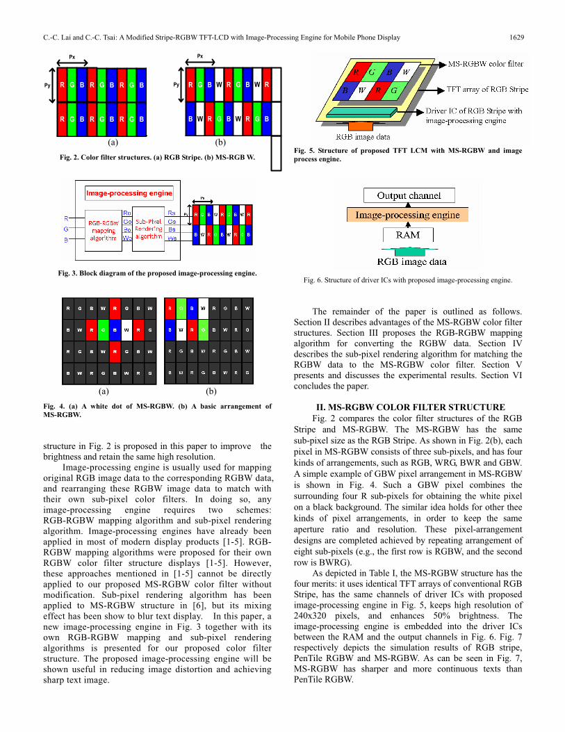
(a) (b) Fig. 2. Color filter structures. (a) RGB Stripe. (b) MS-RGB W.
Fig. 3. Block diagram of the proposed image-processing engine.
(a) (b) Fig. 4. (a) A white dot of MS-RGBW. (b) A basic arrangement of MS-RGBW.
structure in Fig. 2 is proposed in this paper to improve the brightness and retain the same high resolution.
Image-processing engine is usually used for mapping original RGB image data to the corresponding RGBW data, and rearranging these RGBW image data to match with their own sub-pixel color filters. In doing so, any image-processing engine requires two schemes: RGB-RGBW mapping algorithm and sub-pixel rendering algorithm. Image-processing engines have already been applied in most of modern display products [1-5]. RGB- RGBW mapping algorithms were proposed for their own RGBW color filter structure displays [1-5]. However, these approaches mentioned in [1-5] cannot be directly applied to our proposed MS-RGBW color filter without modification. Sub-pixel rendering algorithm has been applied to MS-RGBW structure in [6], but its mixing effect has been show to blur text display. In this paper, a new image-processing engine in Fig. 3 together with its own RGB-RGBW mapping and sub-pixel rendering algorithms is presented for our proposed color filter structure. The proposed image-processing engine will be shown useful in reducing image distortion and achieving sharp text image.
Fig. 5. Structure of proposed TFT LCM with MS-RGBW and image process engine.
Fig. 6. Structure of driver ICs with proposed image-processing engine.
The remainder of the paper is outlined as follows. Section II describes advantages of the MS-RGBW color filter structures. Section III proposes the RGB-RGBW mapping algorithm for converting the RGBW data. Section IV describes the sub-pixel rendering algorithm for matching the RGBW data to the MS-RGBW color filter. Section V presents and discusses the experimental results. Section VI concludes the paper.
II. MS-RGBW COLOR FILTER STRUCTURE Fig. 2 compares the color filter structures of the RGB
Stripe and MS-RGBW. The MS-RGBW has the same sub-pixel size as the RGB Stripe. As shown in Fig. 2(b), each pixel in MS-RGBW consists of three sub-pixels, and has four kinds of arrangements, such as RGB, WRG, BWR and GBW. A simple example of GBW pixel arrangement in MS-RGBW is shown in Fig. 4. Such a GBW pixel combines the surrounding four R sub-pixels for obtaining the white pixel on a black background. The similar idea holds for other thee kinds of pixel arrangements, in order to keep the same aperture ratio and resolution. These pixel-arrangement designs are completed achieved by repeating arrangement of eight sub-pixels (e.g., the first row is RGBW, and the second row is BWRG).
As depicted in Table I, the MS-RGBW structure has the four merits: it uses identical TFT arrays of conventional RGB Stripe, has the same channels of driver ICs with proposed image-processing engine in Fig. 5, keeps high resolution of 240x320 pixels, and enhances 50% brightness. The image-processing engine is embedded into the driver ICs between the RAM and the output channels in Fig. 6. Fig. 7 respectively depicts the simulation results of RGB stripe, PenTile RGBW and MS-RGBW. As can be seen in Fig. 7, MS-RGBW has sharper and more continuous texts than PenTile RGBW.
1630 IEEE Transactions on Consumer Electronics, Vol. 53, No. 4, NOVEMBER 2007
Table I. Performance Comparison between RGB Stripe, VS RGBW, Checkerboard RGBW, Kodak’s RGBW and proposed MS-RGBW.
2.2 inch QVGA TFT LCD Color filter structure
RGBStripe
VS RGBW Checkerboard RGBW
Kodak’s RGBW
Proposed MS-RGBW
Data channel number 240x3 240x4 240x2 240x3 240x3
Scan channel number 320 320 320x2 320 320
Pixel pitch (um) 141x141 141x141 141x141 188x141 141x141
Sub-Pixel pitch (um) 47x141 35.2x141 70.5x70.5 47x141 47x141
Aperture ratio 60% 47% 47% 60% 60% Transmittance ratio 7% 8.2% 8.2% 10% 10%
Resolution 240x320 240x320 240x320 180x320 240x320
(a)
(b)
(c)Fig. 7. Text comparisons using different color structures. (a) RGB stripe. (b) PenTile RGBW. (c) MS-RGBW.
III. RGB-RGBW MAPPING ALGORITHM The objective of this section is to map the RGB image
data into the RGBW image data pixel by pixel in Fig. 8. In designing this RGB-RGBW mapping algorithm, the hue and the saturation of the original color are preserved and the corresponding luminance is enhanced. The algorithm takes the following steps. Step1: input R, G and B image data of each pixel. Step2: obtain the mapping gain M from (1).
),,(),,(
BGRMaxBGRMinM (1)
where ),,( BGRMin and ),,( BGRMax denote the minimum and maximum of R,G and B, respectively.
Step3: calculate the parameter oW from (2).
),,( BGRMinWo (2)
Fig. 8. Block diagram of RGB-RGBW mapping algorithm.
Step4: generate new R, G, and B image data of each pixel from (3).
o
o
o
WWW
BGR
MM
M
BoGoRo
*100
010001
(3)
On the basis of the HSV color space, it can be shown that the image data, Ro, Go, Bo and Wo, are no distortion in hue and saturation. Using (4) and (5),
(1 ) (1 )60 60 60(1 ) (1 )o
Go Bo M G M B G BH HRo Bo M R M B R B
(4)
SBGRMaxBGRMin
BGRMaxMBGRMinM
BoGoRoMaxBoGoRoMinS o
),,(),,(1
),,(*)1(),,(*)1(1
),,(),,(1 (5)
one shows that the image obtained from the RGB-RGBW mapping algorithm has the same hue and saturation as in the original image pixel by pixel. By using (6),
( , , ) (1 )* ( , , ) (1 )*oV Max Ro Go Bo M Max R G B M V (6) it is shown that the enhanced luminance is (1+M) times the original one.
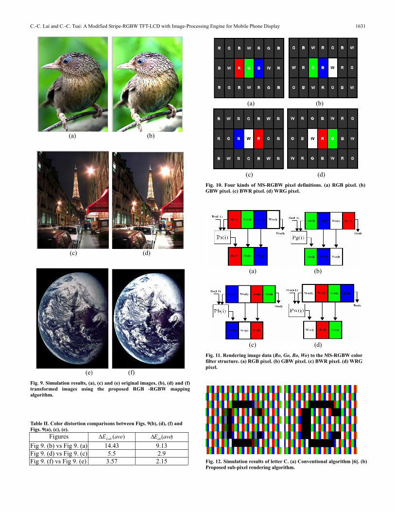
Fig. 9 respectively depicts the simulation results of the proposed RGB-RGBW mapping algorithm. In Figs. 9(b) and (d), the resulting images are clearly brighter than their original ones. Furthermore, through the simulation results in Table II, the proposed method is shown capable of low color distortion ( )(aveEab
<10.0) in the Lab color space, where
)(aveEab denotes the averaged error of total pixels in terms
of a and b from (7). Besides, let )(aveELab represent the
averaged error of total pixels in terms of L, a, and b via (8). 1/ 22 2
1
( ) ( ) ( ) ( )( )
m p o p o
abn
a n a n b n b nE ave
m (7)
1/22 2 2
1
( ) ( ) ( ) ( ) ( ) ( )( )
m p o p o p o
Labn
L n L n a n a n b n b nE ave
m (8)
where )(),(),( nbnanL ppp and )(),(),( nbnanL ooo
are respectively the values of L, a, and b at the nth pixel of the transformed and original images. As shown in Table II, the significant difference between ( )LabE ave and )(aveEab
( ( )LabE ave
> )(aveEab) is definitely attributed to the proposed
MS-RGBW which is designed to enhance image brightness.
C.-C. Lai and C.-C. Tsai: A Modified Stripe-RGBW TFT-LCD with Image-Processing Engine for Mobile Phone Display 1631
(a) (b)
(c) (d)
(e) (f) Fig. 9. Simulation results, (a), (c) and (e) original images, (b), (d) and (f) transformed images using the proposed RGB -RGBW mapping algorithm.
Table II. Color distortion comparisons between Figs. 9(b), (d), (f) and Figs. 9(a), (c), (e).
Figures )(aveELab )(aveEab
Fig 9. (b) vs Fig 9. (a) 14.43 9.13 Fig 9. (d) vs Fig 9. (c) 5.5 2.9 Fig 9. (f) vs Fig 9. (e) 3.57 2.15
(a) (b)
(c) (d) Fig. 10. Four kinds of MS-RGBW pixel definitions. (a) RGB pixel. (b) GBW pixel. (c) BWR pixel. (d) WRG pixel.
(a) (b)
(c) (d) Fig. 11. Rendering image data (Ro, Go, Bo, Wo) to the MS-RGBW color filter structure. (a) RGB pixel. (b) GBW pixel. (c) BWR pixel. (d) WRG pixel.
Fig. 12. Simulation results of letter C. (a) Conventional algorithm [6]. (b) Proposed sub-pixel rendering algorithm.
1632 IEEE Transactions on Consumer Electronics, Vol. 53, No. 4, NOVEMBER 2007
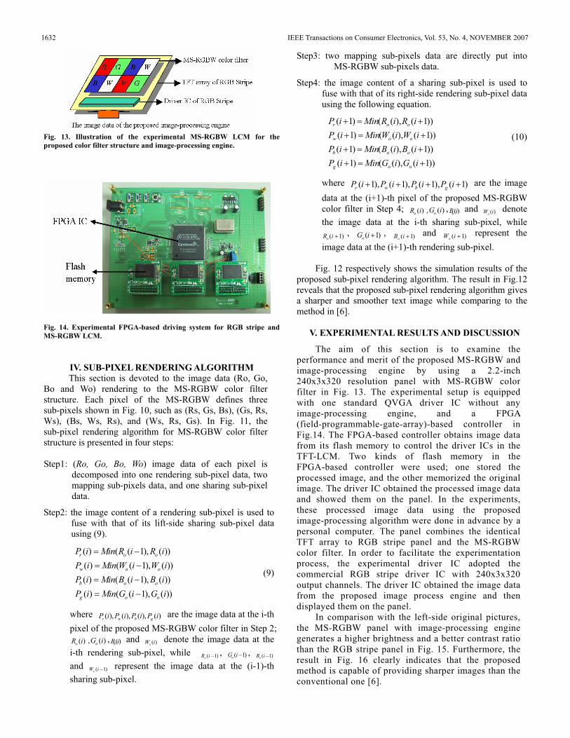
Fig. 13. Illustration of the experimental MS-RGBW LCM for the proposed color filter structure and image-processing engine.
Fig. 14. Experimental FPGA-based driving system for RGB stripe and MS-RGBW LCM.
IV. SUB-PIXEL RENDERING ALGORITHM This section is devoted to the image data (Ro, Go,
Bo and Wo) rendering to the MS-RGBW color filter structure. Each pixel of the MS-RGBW defines three sub-pixels shown in Fig. 10, such as (Rs, Gs, Bs), (Gs, Rs, Ws), (Bs, Ws, Rs), and (Ws, Rs, Gs). In Fig. 11, the sub-pixel rendering algorithm for MS-RGBW color filter structure is presented in four steps:
Step1: (Ro, Go, Bo, Wo) image data of each pixel is decomposed into one rendering sub-pixel data, two mapping sub-pixels data, and one sharing sub-pixel data.
Step2: the image content of a rendering sub-pixel is used to fuse with that of its lift-side sharing sub-pixel data using (9).
( ) ( ( 1), ( ))( ) ( ( 1), ( ))( ) ( ( 1), ( ))( ) ( ( 1), ( ))
r o o
w o o
b o o
g o o
P i Min R i R iP i Min W i W iP i Min B i B iP i Min G i G i
(9)
where ( ), ( ), ( ), ( )r w b gP i P i P i P i are the image data at the i-th pixel of the proposed MS-RGBW color filter in Step 2;
( )oR i , ( )oG i , ( )bB i and ( )oW i denote the image data at the i-th rendering sub-pixel, while ( 1)oR i , ( 1)oG i , ( 1)oB i
and ( 1)oW i represent the image data at the (i-1)-th sharing sub-pixel.
Step3: two mapping sub-pixels data are directly put into MS-RGBW sub-pixels data.
Step4: the image content of a sharing sub-pixel is used to fuse with that of its right-side rendering sub-pixel data using the following equation.
))1(),(()1())1(),(()1())1(),(()1(
))1(),(()1(
iGiGMiniPiBiBMiniPiWiWMiniP
iRiRMiniP
oog
oob
oow
oor
(10)
where )1(),1(),1(),1( iPiPiPiP gbwr are the image
data at the (i+1)-th pixel of the proposed MS-RGBW color filter in Step 4; ( )oR i , ( )oG i , ( )bB i and ( )oW i denote the image data at the i-th sharing sub-pixel, while
)1(iRo, )1(iGo
, )1(iBo and )1(iWo
represent the image data at the (i+1)-th rendering sub-pixel.
Fig. 12 respectively shows the simulation results of the proposed sub-pixel rendering algorithm. The result in Fig.12 reveals that the proposed sub-pixel rendering algorithm gives a sharper and smoother text image while comparing to the method in [6].
V. EXPERIMENTAL RESULTS AND DISCUSSION
The aim of this section is to examine the performance and merit of the proposed MS-RGBW and image-processing engine by using a 2.2-inch 240x3x320 resolution panel with MS-RGBW color filter in Fig. 13. The experimental setup is equipped with one standard QVGA driver IC without any image-processing engine, and a FPGA (field-programmable-gate-array)-based controller in Fig.14. The FPGA-based controller obtains image data from its flash memory to control the driver ICs in the TFT-LCM. Two kinds of flash memory in the FPGA-based controller were used; one stored the processed image, and the other memorized the original image. The driver IC obtained the processed image data and showed them on the panel. In the experiments, these processed image data using the proposed image-processing algorithm were done in advance by a personal computer. The panel combines the identical TFT array to RGB stripe panel and the MS-RGBW color filter. In order to facilitate the experimentation process, the experimental driver IC adopted the commercial RGB stripe driver IC with 240x3x320 output channels. The driver IC obtained the image data from the proposed image process engine and then displayed them on the panel.
In comparison with the left-side original pictures, the MS-RGBW panel with image-processing engine generates a higher brightness and a better contrast ratio than the RGB stripe panel in Fig. 15. Furthermore, the result in Fig. 16 clearly indicates that the proposed method is capable of providing sharper images than the conventional one [6].

C.-C. Lai and C.-C. Tsai: A Modified Stripe-RGBW TFT-LCD with Image-Processing Engine for Mobile Phone Display
(a) (b)
(c) (d)
(e) (f) Fig. 15. Experimental results. (a), (c) and (e) Original images and RGB stripe color filter. (b), (d) and (f) Transformed images using the proposed image-process engine and MS-RGBW color filter.
Fig. 16. Experimental results of letter C. (a) Conventional algorithm [6]. (b) Proposed sub-pixel rendering algorithm.
VII. CONCLUSIONSThis paper has presented a MS-RGBW color filter
structure with a novel image-processing engine. The image-processing engine is equipped with two new algorithms: RGB-RGBW mapping algorithm and sub-pixel rendering algorithm. The proposed techniques not only retain the same high resolution, but also obtain a higher brightness
and a shaper image than the conventional one. The proposed RGB-RGBW mapping algorithm easily obtains a color mapping without hue and saturation distortion in the pixel level. Numerous simulation results have been provided to confirm the aforementioned merits of the proposed techniques. Through experimental results, the proposed techniques have been shown useful and effective for 2.2-inch TFT LCDs with MS-RGBW color filter structure.
ACKNOWLEDGEMENTS The authors wish to acknowledge Mr. Jyun-Sian Li and Mr. Ching-Fu Hsu at Wintek Corporation, Taiwan, for preparing the simulation and experimental results.
REFERENCES[1] B. W. Lee, C. Park, S. Kim, T. Kim, Y. Yang, J. Oh, J. Choi, M. Hong, D.
Sakong, and K. Chung, “TFT-LCD with RGBW Color System,” SID2003 Digest of Technical Papers, 2004, pp.1212-1215.
[2] B. W. Lee, K. Song, Y. Yang, C. Park, J. Oh, C. Chai, J. Choi, N. Roh, M. Hong, and K. Chung, “Implementation of RGBW Color System in TFT-LCDs,” SID2004 Digest of Technical Papers, 2004, pp.111-113.
[3] A. D. Arnold, T. K. Hatwar, M. V. Hettel, P. J. Kane, M. E. Miller, M. J. Murdoch, J. P. Spindler and S. A. Van Slyke, “Full-Color AMOLED with RGBW Pixel Pattern,” Proceedings of the 24th International Display Research Conference, 2004, pp. 252-255.
[4] H. J. Yoon, J. H. Lee, K. P. Hong, J. Y. Chun, B. Y. Ryu, J. M. Jun and J. Y. Lee, “Development of the RGBW TFT-LCD with Data Rendering Innovation Matrix(SRIM),” SID2005 Digest of Technical Papers, 2005, pp.244-247.
[5] C. Y. Tsai, Y. C. Tsai, Y. J. Chang, W. C. Chang and D. L.P. Ting, “Advanced Transmissive-LCDs with High Reflectance in RGBW,” Proceeding of the 13th International Display Workshops, 2006, pp.809-810.
[6] S.T. Lo and R. S. Weng, “Method and apparatus for four-color data converting,” US patent #20060274212, 2006.
Chih-Chang Lai received the B.S. degree in Electrical Engineering from National Taiwan Ocean University in 1997 and M.S. degree in Electrical Engineering from National Chung-Hsing University in 1999, respectively. During 1997-1999, he was a research assistant in Advanced Electrical Control Lab (AECL), National Chung Hsing University, for studying mobile robot control systems using Kalman
filter and fuzzy control theory. Since 2001, he has been a project leader in Taiwan Wintek Corp. Currently; he is working toward his Ph.D. degree at Department of Electrical Engineering, National Chung Hsing University. His current interests include neural networks, fuzzy control and their applications to display modules and image processing
Ching-Chih Tsai received the Diplomat in Electrical Engineering from National Taipei Institute of Technology, Taipei, Taiwan, ROC, the MS in Control Engineering from National Chiao-Tung University, Hsinchu, Taiwan, ROC and the PhD in Electrical Engineering from Northwestern University, Evanston, IL,USA, in 1981, 1986 and 1991, respectively. Currently, he is a Professor in the Department of Electrical Engineering, National Chung-Hsing University, Taichung, Taiwan, ROC. From 2001 to
2003, he served as the Chair at Taipei chapter, IEEE control systems society, and, from 2003 to 2005, he served as the Director at Center for Research Development and Engineering Technology, College of Engineering, National Chung-Hsing University. In 2006, he served as the Chair at Taipei chapter, IEEE Robotics and Automation society, and the Director at Center for Advanced Industry Technology and Precision, National Chung Hsing University. Since 2007, he has been the President, Taichung Chapter, the Chinese Institute of Engineers.
1633


![Flexstrip 115 RGBW Rot Spectrum - AUTLED · Flexstrip 115 RGBW Rot . Spectrum . Measurement name: FS-115-RGBW Rot. Measurement time: 2016-04-19 14:14:05 ... 49.7798 Power [W] 26,04](https://static.fdocuments.us/doc/165x107/5b9303f209d3f280378c6cc4/flexstrip-115-rgbw-rot-spectrum-flexstrip-115-rgbw-rot-spectrum-measurement.jpg)