A Modeling TeChnique for STOVL -:' == Eject0rand ... · PDF fileA Modeling TeChnique for...
14
NASA Technical Memorandu_..]_0_.!_67- . _ i ................................... AIAA-90-2417 _ ii_ _ ......................... _ 15 " - i_:= A Modeling TeChnique for STOVL -:'_== Eject0rand-VoiumeDynamics - C.K. Drummond and W_S. B0ra_iewicz Lewis Research Center Cleveland, Ohio .... (NASA-TM-I03167) A MOD[LING TECHNIOUE FOP, Ng0-2P569 :_:_:- $TUVL EJECTOR A_O VOLUM_ DYNAMICS (NASA) Uncl _s G3/07 02615R8 prepared for the _- ................ 26th Joint Propulsion conference cosponsored by the AIAA, SAE, ASME, and ASEE - Orlando, Florida, July 16-18, 1990 https://ntrs.nasa.gov/search.jsp?R=19900013250 2018-05-07T03:22:47+00:00Z
Transcript of A Modeling TeChnique for STOVL -:' == Eject0rand ... · PDF fileA Modeling TeChnique for...

NASA Technical Memorandu_..]_0_.!_67- . _ i ...................................
AIAA-90-2417 _ ii_ _......................... _ 15 " - i_:=
A Modeling TeChnique for STOVL-:'_== Eject0rand-VoiumeDynamics -
C.K. Drummond and W_S. B0ra_iewicz
Lewis Research Center
Cleveland, Ohio ....
(NASA-TM-I03167) A MOD[LING TECHNIOUE FOP, Ng0-2P569 :_:_:-
$TUVL EJECTOR A_O VOLUM_ DYNAMICS (NASA)
Uncl _s
G3/07 02615R8
prepared for the _- ................26th Joint Propulsion conferencecosponsored by the AIAA, SAE, ASME, and ASEE
- Orlando, Florida, July 16-18, 1990
https://ntrs.nasa.gov/search.jsp?R=19900013250 2018-05-07T03:22:47+00:00Z


A MODELING TECHNIQUE FOR STOVL EJECTOR AND VOLUME DYNAMICS
C. K. Drummond* and W. s. Barankmwacz
National Aeronautics and Space AdministrationLewis Research Center
Cleveland, Ohio 44135
05t-v-)
II..ul
&b.ar_araNew models for thrust augmenting ejector performance
prediction and feeder duct dynamic analysis are presentedand applied to a proposed STOVL aircraft configuration.Central to the analysis is the nontraditional treatment ofthe time-dependent volume integrals in the otherwiseconventional control-volume approach. In the case of thethrust augmenting ejector, the analysis required a newrelationship for transfer of kinetic energy from the primaryflow to the secondary flow. Extraction of the requiredempirical corrections from current steady-state exper-imental data is discussed; a possible approach for modellinginsight through CFD is presented.
Nomenclature
A cross-sectional area
to jet half-widthB channel half-width
C L empirical coefficientd effective nozzle diameter
It enthalpy
KE kinetic energym mass flowrale
m,o control volume massA:t momentum flux
M co control volume momentum
A,ILe Mach number of primary nozzle flow
P pressuret time
v vclocity[r volume
h/ unit depth of control volumex transverse coordinate
z strcamwise coordinate
p density+ self-similar profilc flmctiono lurbulcnt flow constanl
_, dimcnsionlcss transvcrsc coordinate_ab_crJ_t_
cv control volumee entrained stream
m primary stream centerline1s secondary steam at station 1
1 p primary stream at station 1
*Aerospace Engineer, Member AIAA**Aerospace Engineer
Copyright © 1990 by the American Institute of Aeronauticsand Astronautics, Inc. No copyright is asserted in the
United States under Title 17, U.S. Code. The U.S. Govern-ment has a royalty-free license to exercise all rights underthe copyright claimed herein for Governmental purposes.
All other rights are reserved by the copyright owner.
Thrust augmenting ejectors are candidate componenetsfor powered lift propulsion subsystems of Short Take-OffVertical Landing (STOVL) aircraft. Figure 1 illustrates thata typical ejector is a mechanically simple device in which aconvergent nozzle is placed within a shroud; in the case ofSTOVL aircraft, the wing and fuselage act as part of the
shroud. Except for a valve to control flow through the nozzlefeeder duct, no other parts of this system are required to
move during ejector operation (portions of the ejector can,however, fold away for forward flight).
Interest in the dynamic responsc of an ejector systemextends from an effort to develop a complete propulsion
system simulation for ASTOVL aircraft (Mihalocw andDrummond, 1989; Akhtcr et. al., 1989). Propulsion systemsimulations that run in real-time are an important part of
research on design mcthodologies for Integrated Flight andPropulsion Control (IFPC) systems. In this context a usefulejector characteristic to know is the frequency response ofejector thrust output (due to a change in the primary nozzleflow condition). If the ejector response is outside thebandwidth of the flight control system (see Figure 2) then
a simple quasi-steady ejector model is all that is needed forthe propulsion system simulation. In such a case the ejectormodel could be, for instance, a simple table look-up; this
approach readily meets real-time simulation constraints(on the AD100 real-time simulation computer, a tablelook-up consumes about 2 microseconds).
On the other hand, if the ejector response falls withinthe range of the flight control (or if a new ejector systemhas an unknown response) a high-fidelity ejector modelmust be constructed. Since accuracy is typically synonymous
with a significant amount of model detail, constructing atransient ejector model to mcet the real-time simulationrequirement is a fairly difficult task. Also, the need topredict transient ejector performance aggravatcs a morefundamental modelling problem extending from anincomplete picture of steady-state ejector phenomena.
For simplicity in discussion and analysis, an ejectorsystem is usually subdivided along functional lines intoaninlet, mixing region, and diffuser. Porter and Squires (1981)
present a perspective whereby an ejector gas flow under-goes changes analogous to those of a gas turbine: bothsystems have an inlet and nozzle (diffuser), but in an ejectorthe compression, combustion (energy addition), and tur-bine processes are contained within the mixing region.
Compression of and energy addition to the secondary flowresults from interaction with the primary flow; the energy

obtainedbyexpansionof the primary nozzle flow is anal-ogous to the energy input a turbine provides. It is interestingthat the potential for augmentation of the primary ejectorthrust is understood clearly to be a function of the reduced"ambient" pressure the primary nozzle discharge sees; whatis less understood is the detailed mechanism of the
primary-secondary entrainment phenomenon responsiblefor that environment. Central to improving our under-standing of the interaction between the primary and sec-ondary flow is a better understanding of the physics behindturbulent, compressible flow shear layers (Goebel andDutton, 1990, provide a recent look at this problem).
One approach to the ejector analysis is based on firstprinciples and typically blends the mean value equations formomentum, energy and heat with phenomenologial modelsof turbulence for closure (Anderson et. al., 1984; Townsend,1980). Finite-difference, finite-element, or spectral meth-ods of analysis are then employed for the discretization and
solution of the final system of equations (Peyret and Taylor,1983). These solution methods are representative ofmodern Computational Fluid Dynamics (CFD). AlthoughCFD provides a rigorous approach to analysis of theflowfield, it is not expected that real-time solutions areachievable in the forseeable future.
Another problem concerns identification of theappropriate boundary conditions and turbulence model to
use for the description of the mixing region. It appears thestate-of-the-art provides steady-flow predictions moreaccurate in an integral sense (pressure, thrust) thanpointwise (velocity). For instance, Deese and Agarwal(1988) investigated several CFD analyses (including theirown) and remark on the general failure to produce "ac-ceptable" velocity profiles. The capability to predicit thrustis encouraging, but wall shear stress estimates will not bemore accurate than the velocities computed. Modern CFDanalyses designed to attack these problems is an active areaof research (see, for instance, Lowrie, 1990; Choi and Soh,1990).
Control-Volume Approach
An alternative to CFD is the control-volume approach.In this case the governing equations express "bulk" con-servation of mass, momentum, and energy. Although thecontrol-volume method greatly simplifies the mathematicalanalysis, the opportunity to introduce a detailed mathe-matical description of any transport mechanisms is often
lost. Real-flow effects are generally introduced through lossfactors (nozzle coefficient; wall friction factor) or specifiedskewness conditions (non-uniform secondary or mixed flowprofiles). By default, such corrections are accurate for themodel tested, but tend to be configuration dependent andhave unknown scale effects. Despite criticizm thatcontrol-volume predictions devoid of empirical correctionfactors do not rigourously account for mixing, entrainment,and boundary-layer effects, this approach has been thefoundation for many steady-flow ejector performancepredictions exhibiting rapid execution speed of execution
and acceptable engineering accuracy. We find this to be anattractive foundation for the exploration of a transient flowsimulation.
Here, a transient flow is a 'temporary' unsteady flow,associated with, for example, a change in ejector operationfrom one steady-state condition to another. Contrast this
with oscillatory flows in which a periodic time-asymptoticflow character is exhibited. Ejectors utilizing pulsed pri-mary nozzle flows are of the latter type. In the presentsimulation the focus on transient, not oscillatory, ejectorphenomena descends from flight-critical aircraft fightcontrol scenarios; an example would be transition to for-ward flight from vertical take-off.
A basic difficulty in application of the control-volumemethod to the study of transient flows is in the treatmentof the time-dependent volume integrals -- unless youconsider the flow quasi-steady, it is essential these terms beincluded in the problem formulation. One solution to thismodelling problem to draw in as many assumed features ofthe flowfield as possible.
Scope of Work
An empirically based model for the jet mixing turbulentinteraction region is explored within the framework of acontrol volume analysis. Three fundamental assumptionsare discussed in the present work that reduce the transientejector analysis problem to an attractively simple system ofequations. We also remark on a control-volume approachto simulation of duct dynamics. In comparison with theejector analysis, the mathematical treatment is considerablysimplified by the absence of a secondary flow. Generallythe focus of discussion is on the transient features of the
analysis since the treatment of steady-state flows is givenin, for instance, Addy and Dutton (1974).
Estimation of the empirical coefficients required in thecontrol-volume method of analysis is discussed. Typicalresults from the ejector and duct analysis for a proposedSTOVL aircraft are presented. Preliminary finite-elementCFD results for the ejector mixing region are also pres-ented; CFD is being pursued as one means to augment theejector modeling process.
In an unsteady flow problem, considerable mathemat-ical convenience follows when a quasi-steady flowfieldresponse can be assumed -- the time-derivative terms in thegoverning differential equations can be dropped. At eachinstant in time the flow is assumed to respond instantly toboundary condition changes. The validity of such anassumption, however, requires the characteristic time of theforcing function to be the same as (or greater than) therelaxation time of the flow. For a given flowfield distur-bance, pressure forces respond more quickly than viscousforces, so the former are therefore more appropriatelytreated as quasi-steady.
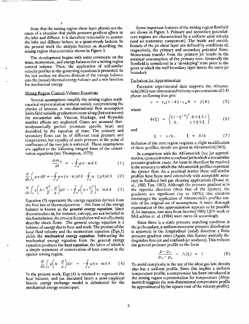
Notethatthemixingregionshearlayerphysicsarethecause of a situation that yields pressure gradient effects inthe inlet and diffuser. It is therefore reasonable to assume
the inlet and diffuser behave in a quasi-steady fashion. Inthe present work the analysis focuses on describing themixing region characteristics shown in Figure 3.
The development begins with some comments on themass, momentum, and energy balances for a mixing region
control volume. Then, the application of serf-similarvelocity profiles to the governing equations is presented. Inthe last section we discuss division of the energy balanceinto the (usual) thermal energy balance and a new functionfor mechanical energy.
_matr_-Y_olttme_Equ atiom
Several assumptions simplify the mixing region math-ematical representation without unduly compromising thephysics of interest. A one-dimensional flow assumptionlimits field variable gradients to occur along (but not across)the streamwise axis. Viscous, blockage, and Reynoldsnumber effects are neglected. Gases are assumed ther-
modynamically perfect (constant specific heat) anddescribed by the equation of state. The primary andsecondary flows can be of different total pressure andtemperature, but equality of static pressure at the point ofconfluence of the two jets is enforced. These assumptionsare applied to the following integral form of the conser-vation equations (see Thompson, 1972):
d rne° f _dt pv" ndA (1)
_tfvPVdV=-SApv(v.n)dA-fan.(pl)dA (2)
O h+--- dV=- p h+__ v'ndA2
(3)
Equation (3) represents the energy equation derived fromthe first law of thermodynamics -- this form of the energybalance is known as the general energy equation. Sincediscontinuities in, for instance, entropy, are not included inthis formulation, the present formulation will not effectivelydescribe shock flows. The general energy equation is abalance of energy due to heat and work. The product of thelocal fluid velocity and the momentum equation (Eqn.2)yields the mechanical energy equation. Subtracting themechanical energy equation from the general energyequation produces the heat equation, the latter of which isa simple statement of conservation of heat content in theejector mixing region,
p(h- )dv = - f ph,,. ndA (4)
In the present work, Eqn.(4) is retained to represent theheat balance, and (as discussed later) a semi-empiricalkinetic energy exchange model is substituted for the
mechanical energy counterpart.
Some important features of the mixing region flowfieldare shown in Figure 3. Primary and secondary potential-core regions are characterized by a uniform axial velocity(and no transverse component). The inside and outsidebounds of the jet shear layer are defined by conditions of,respectively, the primary and secondary potential flows.Momentum transfer from the primary jet results in theeventual consumption of the primary core. Generally theflowfield is considered in a "developing" state prior to thepoint at which the wall boundary layer meets the outer jetboundary.
_App.toximat_
Extensive experimental data supports the Abramo-vich(1963) non-dimensional velocity representations of 2-Dplanar co-flowing free jets:
v = v.(l-¢)+v..4_ = /(¢) (5)
where
and
,i,(_) __ ((1-_s)2.0<-_<-I 1o, i_<__<_(6)
= x/b, _ = _/b (7)
Inclusion of the core region requires a slight modification
of these profiles; deta!l s are given in Abramovich(1963).
In comparison with the Ablramovich free jet approxi-mation, ejectors involve a confined jet in which a streamwisepressure gradient exists. An issue to therefore be resolvedis the accuracy to which the Abramovich profiles representthe ejector flow. As a practical matter these self-similarprofiles have been used extensively with acceptable accu-racy in fluidized bed gas cleaning applications (Donsi et.al., 1980; Tan, 1982). Although the pressure gradient is inthe opposite direction (than that of the ejector), thegradients are significant (up to 100%); this situationencourages the application of Abramovich's profiles out-side of his original set of assumptions. A more thoroughexamination of this approximation appears to be possibleif, for instance, raw data from Storms(1989) LDV work orMcLachlan et. al. (1984) were curve-fit accordingly.
Since there is a static pressure matching condition atthe jet boundary, a uniform transverse pressure distributionis assumed; in the longitudinal (axial) direction a finitepressure gradient exists (Again, this feature partially dis-
tinguishes free-jet and confined-jet analyses). This reducesthe general pressure profile to the form
p-/:),= A(_)= l (8)
p.,- p.
To avoid complexity in the use of the ideal gas law, densityalso has a uniform profile. Since this implies a uniformtemperature profile, a compromise has been introduced inthe mixing region representation for temperature (Abra-movitch suggests the non-dimensional temperature profilebe approximated by the square root of the velocity profile).

Application to the Conservation Equations
Figure 4 illustrates the finite volume descretizationemployed in the present work. Since the implicit assumptionis that the self-similar profiles are the link between the flowstreams in the transverse direction, descretlzation onlyoccurs in the streamwise direction. To capture a repre-sentative variation in flowfield characteristics (Figure 3) itis necessary to divide the mixing region into at least 3elements. We generalize the analysis by defining a genericelement, k, bounded by surfaces at i andj.
Consider the application of the self-similar profiles tothe mass conservation equation. Based on our previous flowassumptions, Equation (1) simplifies to the form
(dra) = m, - rhi (9)
where the mass flux is now written
ria, = p,c,dd = 21V p,u,d_ (10)
From which integration over the self-similar profiles yields
m, = 21gb,p,(O.45v,_+O.fSv_+(_-l)v_),
= 21db,Z I (11)
The time-derivative term in the mass conservation equation
is given by
"_ k = 2IJBAz (12)/
where the characteristic density for the finite volume is nowapproximated by the value of the density at station ] (inpractice this is a good assumption as long as field variablegradients are "modest" in size). If the characteristic jetexpansion width, b, also assumes its value at j, thensubstitution and re-arrangement of the continuity equationyields
(do) = b,Z,., - b,Z,., (13)7-ff j BAz
Computation of the jet half-width, b, derives from themomentum equation for incompressible flow, applied tothefirst finite volume; a rectilinear jet expansion is assumedtherefrom and compressible flow restored for subsequentcalculations (In light of thc recent work of Goebel andDutton (1990), this procedure for computing the jetexpansion angle may need to be refined).
When the self-similar profiles are substituted into themomentum balance, equation (2), the jet centerline velocityderivative can be shown to be
dt Jj 2[gbjLkz p _- *
where
_- 0.45Fl 0.45
M k = 2Wb,(Z2,,+_P,)
(15)
-2Wb,(Z2. j + _Pj) (1 6)
f t z
Zz = Jo P_Ukd_ (17)
Note in equation (14) that the centerline velocity derivativeis a function of the density derivative, equation (13).
Introduction of an ideal gas assumption simplifies theheat equation to the form
-_ pdV = - pyv. ndA (18)
Non-dimensional velocity and pressure profiles provide the
pressure derivative result
(d_t) bkZ,+bk.,Z, bkZo-bk,,Zo=_ +(v-i) (19)k AzB AzB
where Z 1 has been derived previously and Z 0 is given ateach station by
Zo,, = f]p,Ad_ (20)
Equations (13), (14), and (19) are the three differentialequations required for computing the time derivatives ofgas density, pressure, and jet centerline velocity in theejector mixing region. Closure for the problem requircsdefinition of the entrained flow state.
Entrained Kinetic Enerffy_
Analysis of the primary and secondary flow interactionhas not, to this point, been completed. By themselves, theself-similar profiles close the loop for steady-stateflows, butnot transient ones. This section provides an approximationfor the turbulent flow kinetic energy exchange mechanismto characterize the influence of primary flow changes onthe secondary flow. Knowledge of the total changc insecondary flow kinetic energy permits updates to thesecondary flow state during integration of the field variabletime derivatives.
= =
Computations for a specified steady-state conditionshow that the change in kinetic energy due to mLring is notthe same for the Secbndary fl0W as it is for the primary. In
fact, the gain in kinetic energy of the secondary flow isentirely due to the mixing process, while the mixing loss ofthe primary flowis only a fraction of its total loss. In balance,the total change of kinetic energy of the primary flow isgreater than that of the secondary flow.
In the works of Chow and Addy(1964) and Korst andChow(1966) the relationship betwecn the change inentrained flow kinetic energy and the total primary flowkinetic energy for a shear layer are discussed, and the resultscan be expressed in the functional form:
AKE,s = F(KE,,. O} (21)

whereit wasempiricallydeterminedthat- 12(1+0.23M_e) (22)
Thedifficultywiththekineticenergyfunctionasgivenaboveisthatit representsaquasi-steadyconstant-pressureflowapproximation and therefore cannot be used in its presentform for the transient flow analysis. To entertain localtransport of energy, consider the change in secondary flowto be a combination of changes in primary and secondaryflow kinetic energies due to mixing alone,
where the subscript m denotes the change in kinetic energydue exclusively to mixing. Numerical experiments suggestthe form
_xKE','y - eXKE ''_'l,._+_xK_',, _C, (24)
This engineering approximation results in the introduction
of an undetermined constant, C ,. In the present work the
value of the constant is determined by matching transientsolution asymptotes with steady-state performance data (an
example is presented later).
Computation of the gain in secondary flow kineticenergy due to mixing is given by
_KE lS,r¢_ = 'f.)o 5-2 )d_ (2S)
where gdefines the jet boundary streamline (for which the
primary mass flow through station i is equal to primary massflow through j). For the present discussion this dividingstreamline position is assumed known; Korst andChow(1966) discuss the typical approach of analysis.Expanding the equation for the change in kinetic energyyields
AKEIs._=WbO (va-vv2,)d_+ (va-vo_,)d_;
(26)
Substitution of the self-similar profiles into this expressionand integrating the result provides
AKEls.._ =NWbp(va(Hl + H s - F a - F4)
+v._v2_(Ha-F,)+o_v.Hz+V_H4} (27)
where the detailed expressions for the integrals H i and F iare given by Drummond(1988). It should be noted that inthe present work the integrals are independent of time.
Similar to the way in which the change in secondary flowkinetic energywas computed, the energy loss of the primaryflow is given by
AKEi,., = Jo pv_-_ -_(28)
where the limits of integration reflect interest in the domainof the primary jet cross-section.
Evaluation of the integral at station i yields the result
AKE ,e,,. = I'/bp(vaH, + v.v_H2 + v_v_Ha + v_H4
-v_F,-v.v_Fa) (29)
The expressions for the integrals implied in F i and H i canbe obtained from Drummond(19gg).
It is recognized that the mixing length theory of Korsthas only been verified for steady-state flow and, further-more, that a constant pressure assumption was made in hisanalysis. For the transient ejector work, Korst's theory issimply employed as a springboard for a new functionalrelation between the primary and secondary flows.Although the detailed form of the function has not beenvalidated, one must admit that the basic model provides arational foundation for energy exchange and does allowflexibility in future modelling efforts.
_Sammar_
Density, velocity, and temperature are the unknown
ejector mixing region field variables. The proposed controlvolume analysis asks the sub-region be characterized by an'entrained flow' node and a 'jet centerline' node. The initial
value problem links the two nodes through a form of theintegral equations where a self-similar profile assumptionhas been blended in. To proceed forward in time, then, (a)integrate the three jet centerline equations forward onetime step, Co) compute the entrained velocity from thekinetic energy exchange approximation, and (c) update theentrained flow density and pressure by assuming equilib-rium with the primary flow.
Iala2alal.w_
Feeder ducts and tailpipes are 'large-volume' STOVLpropulsion system components whose dynamic response(so called, volume dynamics) are of interest when (a)coupling of static sub-system components is necessary, or(b) gas dynamics effects are potentially significant. A modelthat satisfies both of these situations is desired for the
general ejector system simulation objective.
The proposed model follows directly from the governingequations for mass, momentum, and energy given byEqns.(1)-(3). All of the simplifying assumptions stated forthe ejector are also assumed here.
As before, mass conservation takes the form of a densityderivative
(dp) = m,-m I = rh,-ria 1_- k Vk AAx (30)
where an overbar indicates a volume-average quantity.
5

Flowmomentumchangesin ductsare generallyattributableto variationsin cross-sectionalareaor thefrictionassociatedwithrealflows;thegoverningdifferentialequationisavectorexpression,butundertheassumtiontheunitnormalspointoutwardfromeachboundarythereresultsthescalarbalance
dd---_(pvV)k = M,-Mj+t e (31)
where the scalar form of the momentum is
M = vrh + PA
In this work an idealized expression for the internal
resistance of the duct shown is given by
i A,) (32)f" = -PdA _" -_(P,+P,)(A,-
where the absence of frictional effects should be noted.
Carrying through the differenfiotion in time and re-arranging results in the following equation
(dr) 1 vdpdt _ _Ax(M,-M,+?)-._d---[ (33)
The characteristic velocity v is a weighted average of theinlet and exit control volume velocities
v = _v,+ (1 -_)v, (34)
where _ is a weighting parameter ranging in value from 0to 1.
In the duct analysis the general power equation is usedsince it includes representations of thermal and kinetic
energy,
p h+w-c-jj, = E,-E, (3S)
where
The time-dependent term can be rearranged to read
clot p h + -_ - -ff , y 1 d t d---[+ 2 dr),
and from this an expression for the pressure derivativeobtained
1 (8/9) F "-[--clc vZdP} (37)y- 1 "_ k= {c0'- ') \pv_-+Td-_- ,
Equations (30), (33), and (37) are the required differentialequations to integrate for the prediction of duct dynamics.
Results
A step-change forcing function is a simple yet effectivetransient for examining dynamic system response. In thiswork a step-change in primary nozzle flowrate is imaginedto be a 'worst-case' scenario for STOVL ejector operation
and is therefore considered an appropriate test for thesimulation. For demonstration purposes a flowrate step-change from 18.7 to 21.9 lbm/sec is chosen because (a)experimental steady-state data at each of these operating
points is available, and ,!b) the 17% change in primaryflowrate is well beyond a small"-perturbation examination
(this exercises the system non-linearities). The rectangularmixing region of the proposed STOVL ejector is approxi-mately 1 ft wide (at the throat), 9 ft in depth (along the wingchord axis), and 0.9 ft long. A 260OF primary flow is usedto entrain air at ambient conditions. A hover condition is
assumed (no forward ejector velocity). The feeder duct wasassumed to be straight, 15 ft long, and have a constant 1.1ft diameter.
F,jcclomPredictions
With the STOVL mixing region subdivided into fivefinite-volumes (along the flow axis), the individualcontrol-volume length of 0.18 ft combined with a charac-teristic mixing region velocity of, say, 500 ft/s yields aresidence time (elapsed time for the primary nozzle flowto reach the diffuser exit plane) for the flow of approxi-mately 0.4 ms. The numerical time step must be less thanthis value. A estimate of the stability limit value A t = .12ms
is given by the Courant approximation (At < O.SAx/u).To avoid infringing on this stability limit a computationaltime step of 0.1 ms was chosen for the present work. Anexplicit time stepping scheme is appropriate for thisapplication since the optimal weighting factors for animplicit approach are generally a function of time.
The empirical coefficient C 1 in the transient analysis isrequired for calibration of the function for primary-to--secondary kinetic energy exchange, Equation 24. For astep-function change in the primary flowrate, the ejector,initially operating at a steady-state condition, asymptoticallyapproaches a second steady-state. The desired C I value isthe one that provides a match between the predictedasymptote and the known thrust at the second state. Thrustpredictions are shown in Figure 5; the "best" C1 valueappears to be between 0.3 and 0.35.
For a 760 ft/s initial primary flow velocity, it appearsthe 1,2ms flow residence time is slightly less than half the3 millisecond interval for the thrust to reach a new maxi-
mum, Oscillations in thrust after that point appear to settlein about 5 milliseconds. This profile suggests a second-orderfrequency response of the ejector. Under a second-orderassumption the ejector test case suggests a 0.75 ejectordamping ratio and a natural frequency on the order of300Hz.
An (initially) unexpected feature of the thrust profile isthe dip in thrust immediately following the step-change inprimary nozzle efflux. Examination of the field variableprofiles reveals this is not a numerical problem, but that theincrease in static pressure associated with the instantaneouschange in driving flow temporarily reduces the favorablesub-ambient pressure environment (required for a poten-tial in thrust augmentation) at the primary nozzle discharge.After a short period, the shear layer energy transfer

becomescommensuratewiththeincr.easeinprimaryflowenergyto overcomethiseffect,andtheresponsethencontinuesinanintuitivelyexpectedmanner.
Transientflowcalculationsfortheejectorfeederductwerebasedontheflowprofilepreviouslydescribedfortheejectorprimarynozzle.Theresultsshownin Figure6indicatetheflowrateresponsetimeisnearlyequalto theflowresidencetime(nogasdynamiclag).Thispredictionisintuitivelyreasonablebecauseof thehighflowvelocitiesandrelativelysmallductvolumeinvolved.
Application of CFD for Model Ref'mement
Two assumptions in the modeling technique that mustbe explored further are the self-similar prof'de assumptionand the proposed function for the kinetic energy exchangemechanism. One avenue for examining internal flow con-
ditions is to analyse the internal flowfield with CFD.FIDAP, a commercial CFD finite-element analysis code
(Reference 11), was chosen for this purpose. Although thecode has a time-dependent turbulent flow solution capa-bility, the version of the code employed could not handlecompressibility effects. Also, the CPU requirements forunsteady flow solutions limited our investigation to steadyflow analysis. These practical restrictions aside, FIDAP wasstill considered acceptable for obtaining a "snapshot" of the
internal ejector flow since a few studies hinted at somesuccess with this approach (Sohn, 1989; Bullock andHaroutunian, 1989).
A simple test case was of interest that would focus onprediction of conditions in the mixing region. For thispurpose a simple 2-D turbulent mixing layer configurationwas constructed: a primary jet is discharged through a 0.4inhigh slot into a 4.88in section (constant area) mixing region.At the time of this writing, converged turbulent flow
solutions (using the k - e turbulence model and upwinding)have only been obtained for a 0.5 ft/s primary jet velocity.Although this low a velocity limits the direct applicabilityof the results, some qualitative comments can be made.
The velocity profiles shown in Figure 7a clearly illustratethe potential core region of the primary flow. Thesetransition to a fully developed appearance at the end of theduct (for clarity, only a small region of the 5in by 14in mixingregion is shown). A test of the appropriateness of theAbramovich self-similar profile assumption is shown inFigure 7b. Turbulent flow profiles at the axial stationsz/d= 18 and 30, and the solution for a laminar flow atz/d = 30 are plotted against the Abramovich profile. It isinteresting to note how closely the laminar flow solutionfollows the turbulent approximation. For the turbulent flowcomputation, we observe that the fully-developed profileassumption is clearly more appropriate at z/d = 30 than at18.
It is evident from these results that it is important to
include the potential core in the velocity profile represen-tation. Also, some account of the developing nature of theflow is warranted for z/d < 30.
S.umma_
An ejector simulation method that includes ejectortransients and with the potential to run real-time has beenpresented. The finite volume method permits rapid evalu-ation of the time dependence of field variables in a thrustaugmenting ejector mixing region. For completeverification of the proposed modeling technique it is nec-essary to have available transient ejector performance datato compare with the simulation output. At the present time,however, only steady-state tests have been conducted forthe ejector shown in Figure 1; a test plan is in-progress toexpand our database to include transient flow experimentaldata.
Stability problems appear to be indicating a need forimprovements in the model for the case of choked primarynozzle flows. Although the present model is valid forcompressible flow, entropy changes must be accounted ina more direct way for a proper treatment of shock flowconditions. The self-similar profiles are obviously not
appropriate in dealing with such flows.
Concern over the use of a constant value of C 1 resultsin its variation with limits on the primary flow. It remainsto derive a rational form for a function (instead of a
constant) to be used for matching thust at these extremes.
Futher CFD activity is in-progress for computation of
higher-speed flows and for a geometry that is more rep-resentative of the proposed ejector configuration.
References
1. Abramovich,G. (1963), The Theory of Turbulent Jets,MIT Press.
2. Addy,A. and Dutton,J. (1974),"Ejector-diffuser theoryand experiments," Report No.UILU-ENG-74-4009,University of Illinois at Urbana-Champaign.
3. Akhter, M.M., Vincent, J.H. Berg, D.F., and Bodden,D.S. (1989), "Simulation Development for US/CanadaASTOVL Controls Technology Program," 20th Mod-
eling and Simulation Conference, May 4-5, Pittsburg,Pennsylvania.
4. Anderson, D., Tannehil, J., and Pletcher, R. (1984),Computational Fluid Mechanics and Heat Transfer,New York: McGraw Hill.
5. Bullock, C.E. and Haroutunian, V. (1989), "Analysis ofAir Circulation Patterns Within the Sistine Chapel
With a Proposed Air Conditioning System," Proceed-ings of the Third FIDAP Users Conference, September24-26.
6. Choi, Y. and Soh, S. (1990), "Computational Analysisof the Flowfieid of a Two-Dimensional Ejector
Nozzle," AIAA-90-1901.

14.
7. Chow, W.L. and Addy,A.L. (1964), "Interactionbetween primary and secondary streams of supersonicejector systems and performance characteristics,"AL4A Journal, V.2, No.4, pp.686-695.
8. Deese, J.E. and Agarwal, R.K. (1988), "A NumericalStudy of Viscous Flows in Inlets and Augrnentors,"AIAA-88-O18Z
9. Donsi, G. Massimilla, L. and Colantuoni, L. (1980),"The Dispersion of Axisymmetric Gas Jets in Fluidised
Beds," Fluidization, Grace and Matsen (Eds.) PlenumPress: New York.
10. Drummond, C.K. (1988), "A Control-volume methodof analysis of unsteady thrust augmenting ejectorflows," NASA CR-182203.
11. FluidDynamics International (1987), FIDAP, Volumes1-4, Evanston Illinois.
12. Goebel, S.G. and Dutton, J.C. (1990), "Velocity Mea-surements of Compressible, Turbulent Mixing Layers,"AIAA-90-0709.
13. Korst,H. and Chow,W. (1966), "Non-isoenergetic tur-bulent jet mixing between two compressible streams atconstant pressure," NASA-CR-419.
Lowrie, B. (1990), "A Multi-Zone k-E TurbulenceModel for Complex Configurations", AIAA-90-2001.
15. McLachlan, B.G., Krothapalli, A. and Nagaraja, K.(1984), "Flow Structure within a Heated RectangularJet Ejector," A/AA Paper 84-0571.
16. Mihaloew, J.R. and Drummond, C.K. (1989), "STOVLAircraft Simulation for Integrated Flight and Propul-sion Controls Research," NASA TM-102419.
17. Peyret, R. and Taylor,T. (1982), ComputationalMethods for Fluid Flow, New York: Springer-Verlag.
18. Porter,J. and Squyers,R. (1981),"A summary/overviewof ejector augmentation theory and performance,"USAF Technical Report No.R-91100-9CR-4Z
19. Sohn, J.L. (1989), "Numerical Analysis of Laminar and
Turbulent Incompressible Flows Using the FiniteElement 'Fluid Dynamics Analysis Package FIDAP'",NASA CR-179390.
20. Storms, B.L. (1989), "An Experimental Study of aThree-Dimensional Thrust Augmenting Ejector UsingLaser Doppler Velicometry," NASA CR-177531.
Tan, B.K. (1982), "Filtration of Gases in Modile
Granular Beds," Ph.D. Dissertation, University ofCambridge (U.K.).
Thompson,P. (1972), Compressible Fluid Dynamics,New York: McGraw-Hill.
Townsend, A.A. (1980), The Structure of TurbulentShear Flow, Cambridge University Press.
21.
22.
23.
z
rud _ Z
Fig. 1 Ejector configuration for STOVL aircraft

.=_
hT
oz
I0.0
0.0
-I0.0
0.1
Natural FrequenCyPropulsion Control System Characteristic
(Closed Loop) _ . i....% i
,. Ejedor lesponse
• --. \ ". ' \ (O.Loop)%% %% f
Nominal t \ 1
.--_- l_,=.d _ \ .I - . w | _ I !
I.o 10.0 lOO I00O
Frequency (rad/sec)
Fig. 2 Response of ejector that can be approximated by quasi-steady model
Secondary Flow
' Primar7Potential Core
nner Boundary
-'X
tI
SecondaryPotenlial Core
B
b
\
\'\Outer Boundary
y layer
fix
X
IDevdoping Developed FlowRegime Regime
ii
i
I
!
k-1 k k+l
SI;llion
Fig. 3 Features of the mixing region
Entrained flo_nodes
Station i Station j
1-
_ Mixing Region Nodes
Fig. 4 Computational grid
Entrained Flow
Primary Flow
9

2b-,
,O
-3
1211
1165
1
1075
1030
985
940
21,9 lb_
S
C 1 =
/
/ total predicted thrust
Primary nozzle flowrate
_ = 18.7 10_S
850
0 1.5 3.0 4.5 6.0 75 9.0 10.5
TIME (milliseconds)
12.0
mv
24.1
22.5
20.9
19.3
17.7
Fig. 5 Result from ejector transient flow test case
= _v,+(l-_)u_ _;=0.5
rit 18.7 I b '_$
_Discharge
16.1 I I t I I 1 t r I
0 3 6 9 12 15 18 21 24 27
Fig. 6
Time (ms)
Result from duct transient flow test case
ORIGINAL PAGE IS
OF POOR QUALITY
30
10
=

Primary Flow
FIDAP Turbulent Flow Solution: l0.5 ft/s primary velocity
a) Mixing region velocity predictions
?
"8>,
o¢);>
.o
¢)E
"t3
OZ
100
0.90
0.80
0.70
0.60
0.50
0.40
0.30
0.20
0.10
0.000.00
IDAP Laminar Flow, z/d = 30
_ramovich Theory
......__. FIDAP Turbulent Flow, z/d = 30
FIDAP Turbulent FIo_viz/d =
t I I 1 I I I I
0.10 0.20 0.50 0.40 0.50 0.60 0.70 0,80 0.90 1.00
Nondimensional Transverse Position, x/b
b) Self-similar velocity profiles
Fig. 7 CFD velocity predictions
11
Report Documentation PageNalionat Aeronautics andSpace Administralion
1. Repod No.NASA TM-103167AIAA-90-2417
4, Title and Subtitle
....
2. Government Accession No.
A Modeling Technique for STOVL Ejector and Volume Dynamics
7. Author(s)
C.K. Drummond and W.S. Barankiewicz
9 Performing Organization Name and Address
National Aeronautics and Space Administr_tionLewis Research Center
Cleveland, Ohio 44135-3191
12 Sponsoring Agency Name and Address
National Aeronautics and Space Administration
Washington, I).C. 20546-0001
15. Supplementary Notes
3, Recipient's Catalog No.
5. Report Date
6, Performing Organization Code
8. Performing Organization Report No.
E-5539
10, Work Unit No.
505-62-71
11. Contract or Grant No.
13. Type of Report and Period Covered
Technical Memorandum
14, Sponsoring Agency Code
i
J
Prepared h)r the 26th Joint Propulsion Conference cosponsored by the AIAA, SAE, ASME, and ASEE, Orlando,Florida, July 16-18, 1990.
16. Abstract
New models fi_r thrust au_ncntin_ ejector peribrmance prediction and feeder duct dynamic analysis are presentedand applied to a proposc_TOVL-_aircraft configuration. Central to the analysis is the nontraditional treatment of
the time-dependent volumc'intcgra'[s in the otherwise conventional control-volume approach. In the case of the
thrust augmenting ejector, the analysis required a new relationship for transfer of kinetic energy from the primary
flow to the secondary flow. Extraction of the required empirical corrections from current steady-state
cxperirncntal_d,'ita is discussed; a poss!ble approach for modelling insight through CFD-is presented.f
Jl
=
Sl
s
17. Key Words (Suggested by Author(s))
STOVL propulsion
Ejector augmenterTransient flow
18. Distribution Statement
Unclassified - Unlimited
Subject Category 07
19. Security Classif. (of this report) _[ 20. Security Ctas_ff. (of this page) [ 21. No. of pages
Unclassified Unclassified 12
NASAFORM1626OCT86 *For sale by the National Technical Information Service, Springfield, Virginia 22161
22. Price*
A03

![[Discovery] 1. 2 The F35-B STOVL Joint Strike Fighter Christopher Shoemaker Aerospace Engineering Pennsylvania State University.](https://static.fdocuments.us/doc/165x107/56649e3b5503460f94b2ca74/discovery-1-2-the-f35-b-stovl-joint-strike-fighter-christopher-shoemaker.jpg)