A Modelica VSC-HVDC Average Value Model Implementation and ...
8
A Modelica VSC-HVDC Average Value Model Implementation and its Software-to-Software Validation using an EMT Power System Domain Specific Simulator Mohammed Ahsan Adib Murad 1 Luigi Vanfretti 2 1 School of Electrical Engineering, University College Dublin, Ireland, [email protected] 2 School of Electrical Engineering, KTH Royal Institute of Technology, Sweden, [email protected] Abstract This paper reports the implementation of a three-phase VSC-HVDC model using the Modelica language. The model is suitable for power system simulation where the power electronic circuitry can be represented using equiv- alent voltage and current sources to model the high fre- quency switching process. Differently from the authors previous work, this model is built using as much compo- nents as possible from the MSL (Modelica Standard Li- brary) to represent the three-phase electrical circuit, while implementing the de facto control system models used within typical power system simulation tools. To show the applicability of Modelica for modeling a VSC-HVDC, a software-to-software validation is performed using the EMTP-RV power system simulator. Keywords: VSC, HVDC, power systems, software-to- software validation, power electronics, electro-magnetic transients, DC grids, power systems 1 Introduction 1.1 Motivation High Voltage Direct Current (HVDC) transmission sys- tems have received renewed attention in the last decade due to their applications for long distance power trans- mission, particularly to enable interconnections between distant wind farms and the main electrical grid (Bahrman, 2006). There are two main converter technologies used in HVDCs: Line-Commutated Converter (LCC) and Volt- age Source Converter (VSC), which are used for differ- ent applications in power systems (Abildgaard and Moli- nas, 2012). VSC-based HVDC systems provide certain advantages w.r.t. those based on LCC, including (Reed et al., 2003; Flourentzou et al., 2009), including indepen- dent control of active and reactive power,energy supply to weak and passive grids, etc. An overview of different VSC topologies are reported in (Andersen et al., 2002) and include conventional two- level, multi-level diode-clamped, floating capacitor multi- level converters, etc. Recently, the Modular Multilevel Converter (MMC) tech- nology has been adopted because of its advantages com- pared to other multilevel converter topologies for HVDC applications. With the adoption of MMC-based VSC tech- nologies, modeling and simulation is becoming of crucial importance for different network studies; where modeling and simulation tools are needed in all facets related to their utilization: from design, through implementation, and in their operation. 1.2 Related Works Power system electro-mechanical dynamic modeling and simulation is used for the analysis of dynamic behav- ior of large power networks, and the use of Modelica is now becoming attractive because of several advantages offered by the Modelica language as compared to exist- ing power system simulation tools (Vanfretti et al., 2016; Casella et al., 2016). Another modeling and simulation approach that is important for power system analysis is the Electro-Magnetic Transient (EMT) methodology, and previous work has shown the advantages and limitations of the use of Modelica (Bachmann and Wiesmann, 2000) in adopting the EMT approach. EMT analysis tools, such as EMTP-RV (see http:// emtp-software.com/), are typically used for the anal- ysis of VSC-HVDC systems (Peralta et al., 2012), which allow to analyze their performance for different levels of modeling granularity of the power electronics of these sys- tems (including average value models). To the knowledge of the authors, there only exists two previous implementa- tions of VSC-HVDC models using the Modelica language in the literature (Majumder et al., 2013; Olenmark et al., 2015), however, these have not been implemented-in nor validated-against EMT (Electro-Magnetic Transient)-type power system simulation tools (e.g. EMTP-RV), and more importantly, they are not publicly available. 1.3 Paper Contributions This paper reports the implementation of a three-phase VSC-HVDC average value model, and a power system test model that is compared against EMTP-RV. The aim is to show the potential use and challenges of applying the Modelica language for EMT-type analysis of VSC- HVDC networks when detailed switching circuits do not need to be represented (e.g. system-level control design purposes). DOI 10.3384/ecp17132241 Proceedings of the 12 th International Modelica Conference May 15-17, 2017, Prague, Czech Republic 241
Transcript of A Modelica VSC-HVDC Average Value Model Implementation and ...

A Modelica VSC-HVDC Average Value Model Implementation andits Software-to-Software Validation using an EMT
Power System Domain Specific Simulator
Mohammed Ahsan Adib Murad1 Luigi Vanfretti2
1School of Electrical Engineering, University College Dublin, Ireland, [email protected] of Electrical Engineering, KTH Royal Institute of Technology, Sweden, [email protected]
AbstractThis paper reports the implementation of a three-phaseVSC-HVDC model using the Modelica language. Themodel is suitable for power system simulation where thepower electronic circuitry can be represented using equiv-alent voltage and current sources to model the high fre-quency switching process. Differently from the authorsprevious work, this model is built using as much compo-nents as possible from the MSL (Modelica Standard Li-brary) to represent the three-phase electrical circuit, whileimplementing the de facto control system models usedwithin typical power system simulation tools. To showthe applicability of Modelica for modeling a VSC-HVDC,a software-to-software validation is performed using theEMTP-RV power system simulator.Keywords: VSC, HVDC, power systems, software-to-software validation, power electronics, electro-magnetictransients, DC grids, power systems
1 Introduction1.1 MotivationHigh Voltage Direct Current (HVDC) transmission sys-tems have received renewed attention in the last decadedue to their applications for long distance power trans-mission, particularly to enable interconnections betweendistant wind farms and the main electrical grid (Bahrman,2006). There are two main converter technologies usedin HVDCs: Line-Commutated Converter (LCC) and Volt-age Source Converter (VSC), which are used for differ-ent applications in power systems (Abildgaard and Moli-nas, 2012). VSC-based HVDC systems provide certainadvantages w.r.t. those based on LCC, including (Reedet al., 2003; Flourentzou et al., 2009), including indepen-dent control of active and reactive power,energy supply toweak and passive grids, etc.
An overview of different VSC topologies are reportedin (Andersen et al., 2002) and include conventional two-level, multi-level diode-clamped, floating capacitor multi-level converters, etc.Recently, the Modular Multilevel Converter (MMC) tech-nology has been adopted because of its advantages com-pared to other multilevel converter topologies for HVDC
applications. With the adoption of MMC-based VSC tech-nologies, modeling and simulation is becoming of crucialimportance for different network studies; where modelingand simulation tools are needed in all facets related to theirutilization: from design, through implementation, and intheir operation.
1.2 Related WorksPower system electro-mechanical dynamic modeling andsimulation is used for the analysis of dynamic behav-ior of large power networks, and the use of Modelica isnow becoming attractive because of several advantagesoffered by the Modelica language as compared to exist-ing power system simulation tools (Vanfretti et al., 2016;Casella et al., 2016). Another modeling and simulationapproach that is important for power system analysis isthe Electro-Magnetic Transient (EMT) methodology, andprevious work has shown the advantages and limitationsof the use of Modelica (Bachmann and Wiesmann, 2000)in adopting the EMT approach.
EMT analysis tools, such as EMTP-RV (see http://emtp-software.com/), are typically used for the anal-ysis of VSC-HVDC systems (Peralta et al., 2012), whichallow to analyze their performance for different levels ofmodeling granularity of the power electronics of these sys-tems (including average value models). To the knowledgeof the authors, there only exists two previous implementa-tions of VSC-HVDC models using the Modelica languagein the literature (Majumder et al., 2013; Olenmark et al.,2015), however, these have not been implemented-in norvalidated-against EMT (Electro-Magnetic Transient)-typepower system simulation tools (e.g. EMTP-RV), and moreimportantly, they are not publicly available.
1.3 Paper ContributionsThis paper reports the implementation of a three-phaseVSC-HVDC average value model, and a power systemtest model that is compared against EMTP-RV. The aimis to show the potential use and challenges of applyingthe Modelica language for EMT-type analysis of VSC-HVDC networks when detailed switching circuits do notneed to be represented (e.g. system-level control designpurposes).
DOI10.3384/ecp17132241
Proceedings of the 12th International Modelica ConferenceMay 15-17, 2017, Prague, Czech Republic
241

The remainder of this paper is organized as follows. Sec-tion 2 gives a brief description of the VSC-HVDC model.In Section 3, the model implementation in Modelica is ex-plained, while in Section 4, software-to-software valida-tion results are summarized. Finally, in Section 5, conclu-sions are drawn and future work is outlined.
2 VSC-HVDC ModelIn EMTP-RV two types of VSC-based MMC station mod-els are available, which are based on the results by (Per-alta et al., 2012): Monopole, and Bipole configurationwith ground return. The MMC stations are representedusing four kinds of models: (a) Full detailed model, (b)Detailed equivalent model, (c) Switching function of armmodel, and (d) Average-value model (AVM). The three-phase configuration of the MMC topology assumed bythese models is shown in Figure 1.
SM1ua
SM2ua
SMNua
SM1ub
SM2ub
SMNub
SM1uc
SM2uc
SMNuc
SM1la
SM2la
SMNla
SM1lb
SM2lb
SMNlb
SM1lc
SM2lc
SMNlc
Vdc
vcvbva
Larm Larm Larm
Larm Larm Larm
iua iub iuc
ila ilb ilc
icib
ia
Idc
Vua
Vla
Figure 1. MMC topology.
In this work the AVM model with an high level con-trol system is implemented. The full description of themodel is documented in (Peralta et al., 2012). In this Sec-tion, the most relevant components of the model availablein EMTP-RV are reviewed, as they are replicated in theModelica implementation, in Section 3.
2.1 Average-Value Model (AVM)In an AVM, the power electronic switches (IGBTs) anddiodes are not modeled in detail, instead the MMC be-havior is represented using controlled voltage and currentsources. Thus, an ideal behavior of the internal variablesof the MMC is assumed. For each phase j = a,b,c; thevoltage of the converter is derived from Figure 1, fromwhere,
vconv j =Larm
2di j
dt− v j. (1)
Assuming the total number of sub-modules in eachphase is constant,
vu j + vl j =Vdc (2)
where, vu j and vl j are upper and lower arm voltages. Using(1) and (2) the MMC is represented as a classical VSC.The controlled voltage source in the AC side is determinedby:
vconv j = vre f j
Vdc
2(3)
where, vre f j are the reference voltages generated from theinner controller of the high level control system (i.e. theyare dimensionless quantities in per unit). Based on theprinciple of power balance, the DC side model equationsare derived assuming no energy is stored inside the MMCconverter, as follows
VdcIdc = ∑j=a,b,c
vconv j i j (4)
where the DC side current is given by,
Idc =12 ∑
j=a,b,cvre f j i j. (5)
Using these principles, the AVM model implementationin EMTP-RV allows to build up an entire VSC-HVDCmodel. Figures 2 and 3 show the schematic of the im-plementation of the two basic components as available inEMTP-RV for this purpose.
AC SidePhase A
VDCVaref
Vac AC SidePhase B
VDCVbref
Vac AC SidePhase C
VDCVcref
Vac
Larm Larm Larm
AC
Figure 2. AC side of AVM model.
IDC
DC_SideVaref
Vbref
Vcref
Ia
Ib
Ic
Req_DC
Leq_DC
C1
P
N
Figure 3. DC side of AVM Model.
In Figure 2 the AC side voltage for each phase is calcu-lated using (3) and Larm is the arm inductance. In Fig-ure 3 the DC side current IDC is calculated using (5)and equivalent inductance, total conduction loss and theequivalent capacitor are given by, Leq_DC = (2/3)Larm,Req_DC = (2/3)NRON and C1 = 6C/N; where N is thenumber of sub-modules per arm, C is calculated usingthe energy conservation principle, and RON represents theconduction loss of each IGBT.
A Modelica VSC-HVDC Average Value Model Implementation and its Software-to-Software Validation usingan EMT Power System Domain Specific Simulator
242 Proceedings of the 12th International Modelica ConferenceMay 15-17, 2017, Prague, Czech Republic
DOI10.3384/ecp17132241

2.2 Control SystemThe VSC type MMC topology uses an “upper level” con-trol system, which includes an outer and inner control.The structure of the overall “upper level” control systemis shown in Figure 4. The “upper level” control systemserves two main purposes: (i) to regulate “system vari-ables”, i.e. the active and/or reactive power or voltages(labeled “outer control” in Figure 4), and (ii) to generatereference voltages (vd_re f and vq_re f ), which are usedas input to the AVM.
2.2.1 Upper Level ControlThe VSC-MMC model uses the classical vector controlstrategy. The inputs to the upper level control are three-phase per unit (p.u.) variables, using the matrix in (8),these variables are converted to direct-and-quadrature-axiscomponents rotating at synchronous speed ( dθ
dt ). Thephase angle θ is calculated using a Phase-Locked Loop(PLL). The blocks for Clarke transformation, P/Q/VACcalculations and d-q transformation are used to computethe variables required for the outer and inner controllers.The d-q transformed voltage and currents are calculatedusing the transformation matrix, T , as follows:
idq = Tiabc (6)vdq = T vabc_grid (7)
where
T =23
cos(ωt) cos(ωt − 2π
3 ) cos(ωt + 2π
3 )−sin(ωt) −sin(ωt − 2π
3 ) −sin(ωt + 2π
3 )12
12
12
. (8)
The AC grid voltage, active and reactive power are calcu-lated from the d-q reference,
P = vd id + vqiq (9)Q =−vd iq + vqid (10)
vgrid =√
v2d + v2
q (11)
The signals are converted to per unit (p.u.) quantities be-fore entering to the upper level control system. The outerand inner control block is used to control active power, re-active power, DC and AC voltage. All these controllers arerealized using proportional and integral (PI) control loop.The input to these PI controller loops are the differencebetween the reference (set by the user) and the controlledvariable. The references to the outer control loop are usu-ally fixed set points, that in practice are varied by a remotedispatcher. In this model the references to the outer con-trol loop are fixed and can be varied by the user. The finalblock (d-q to abc) is used to convert the d-q reference tothree-phase voltage references.
3 VSC Model Implementation inModelica
All the components included in the VSC model availablein EMTP-RV are implemented in Modelica and described
next. In addition to the VSC model, an equivalent gen-erator model and a two winding transformer three-phasemodels were also implemented for software validationpurposes.
3.1 AVM Model in ModelicaThe AVM model was implemented using component mod-els from the MSL (Modelica Standard Library). The con-nector models used in the AC side are the three-phaseplug, and in DC side is the single phase positive and nega-tive pin. The AVM model in Modelica is shown in Figure5.
3.2 Upper Level Control in ModelicaNext, all the blocks of the upper level control systemshown in Figure 4 were implemented in Modelica. Asall the controllers in the upper level control system use thesame PI controller implementation, first a PI controller us-ing components from the MSL was implemented. Nextthe Modelica implementation was compared to the oneimplemented in EMTP-RV. After validating this compo-nent against EMTP-RV, the same PI controller was usedin the remaining P, Q, VDC, VAC, inner control and PLLblocks.
3.3 PLL in ModelicaThe phase locked loop (PLL) implemented in Modelica isshown in Figure 6. The main function of the PLL loop is tosynchronize with the phase angle and frequency of the ACgrid voltage. The implementation of the PLL used simi-lar components in Modelica, as those available in the spe-cific power system tool’s documentation/description (i.e.EMTP-RV). Given the fact that the reference documenta-tion has a copyright, so the detail description is not givenhere.
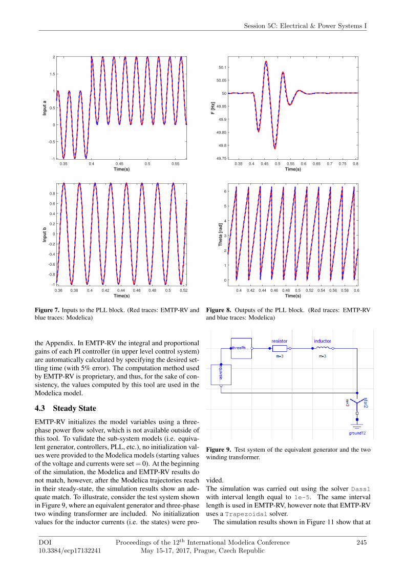
4 Software-to-Software Validation4.1 Sub-system Model ValidationThe AVM and each block of the upper level control sys-tem were implemented as individual models within onepackage, then all the blocks were assembled to realizecomplete the implementation of the VSC model.Next, software-to-software validation was carried outagainst the EMTP-RV model. For example, consider thePLL block shown in Figure 6, it has two inputs and twooutputs. After the implementation of the entire PLL blockin Modelica, this model was validated by simulating it us-ing the same input signals in both Modelica and EMTP-RV. The results of the PLL block simulations are shown inFigures 7 and 8.The same procedure is followed for the three-phase equiv-alent generator and three-phase two winding transformermodels shown in Figure 9. After implementing neededcomponents, a test power system model described next isused to validate the VSC-HVDC model.
Session 5C: Electrical & Power Systems I
DOI10.3384/ecp17132241
Proceedings of the 12th International Modelica ConferenceMay 15-17, 2017, Prague, Czech Republic
243

VDC
P
Q
VAC Grid
P/Q/VAC Calculations
Clarke TR
dq Transformation
PLL
Iq
Id_ref
Iq_ref
Id_ref
Iq_ref
vdvq
idiq
Vd_ref
Vq_ref
Vd_ref
Vq_ref
theta
Outer Control
Inner Control
Linearization & dq to abc
Vabc_refvd
vq
id
iq
V_alpha
V_beta
PQ
VDC
P
Q
VAC Grid
I_alpha_D
I_beta_D
V_alpha_YV_beta_YI_alpha_YI_beta_Y
V_alpha_Y
V_beta_YI_alpha_D
I_beta_D
VDC_meas
Vac_prim
Iac_prim
Vac_secon
Iac_secon
Figure 4. Block diagram of the control system of the VSC-HVDC.
Figure 5. AVM Model in Modelica.
4.2 Power System Test modelThe VSC-HVDC test power system model implementedin Modelica and EMTP-RV is shown in Figure 10. A DCcable model is yet to be implemented in Modelica, andthus, resistive line model (R = 1.022Ω) is used instead.Converter 1 (VSC1) controls the active power and Con-
Figure 6. PLL in Modelica.
verter 2 (VSC2) controls the DC voltage, while 1000 MWactive power is transferred from VSC1 to VSC2. The usercan select which controller should be active in each VSC.The model parameters used (i.e. transformer resistanceand reactance, MMC arm inductance, etc), are exactlythe same in both software tools, and are summarized in
A Modelica VSC-HVDC Average Value Model Implementation and its Software-to-Software Validation usingan EMT Power System Domain Specific Simulator
244 Proceedings of the 12th International Modelica ConferenceMay 15-17, 2017, Prague, Czech Republic
DOI10.3384/ecp17132241
Time(s)
0.35 0.4 0.45 0.5 0.55
Inp
ut
a
-1
-0.5
0
0.5
1
1.5
2
Time(s)
0.36 0.38 0.4 0.42 0.44 0.46 0.48 0.5 0.52
Inp
ut
b
-1
-0.8
-0.6
-0.4
-0.2
0
0.2
0.4
0.6
0.8
Figure 7. Inputs to the PLL block. (Red traces: EMTP-RV andblue traces: Modelica)
the Appendix. In EMTP-RV the integral and proportionalgains of each PI controller (in upper level control system)are automatically calculated by specifying the desired set-tling time (with 5% error). The computation method usedby EMTP-RV is proprietary, and thus, for the sake of con-sistency, the values computed by this tool are used in theModelica model.
4.3 Steady State
EMTP-RV initializes the model variables using a three-phase power flow solver, which is not available outside ofthis tool. To validate the sub-system models (i.e. equiva-lent generator, controllers, PLL, etc.), no initialization val-ues were provided to the Modelica models (starting valuesof the voltage and currents were set = 0). At the beginningof the simulation, the Modelica and EMTP-RV results donot match, however, after the Modelica trajectories reachin their steady-state, the simulation results show an ade-quate match. To illustrate, consider the test system shownin Figure 9, where an equivalent generator and three-phasetwo winding transformer are included. No initializationvalues for the inductor currents (i.e. the states) were pro-
Time(s)
0.35 0.4 0.45 0.5 0.55 0.6 0.65 0.7 0.75 0.8
F [
Hz]
49.75
49.8
49.85
49.9
49.95
50
50.05
50.1
Time(s)
0.4 0.42 0.44 0.46 0.48 0.5 0.52 0.54 0.56 0.58 0.6
Th
eta
[ra
d]
0
1
2
3
4
5
6
Figure 8. Outputs of the PLL block. (Red traces: EMTP-RVand blue traces: Modelica)
Figure 9. Test system of the equivalent generator and the twowinding transformer.
vided.The simulation was carried out using the solver Dasslwith interval length equal to 1e-5. The same intervallength is used in EMTP-RV, however note that EMTP-RVuses a Trapezoidal solver.
The simulation results shown in Figure 11 show that at
Session 5C: Electrical & Power Systems I
DOI10.3384/ecp17132241
Proceedings of the 12th International Modelica ConferenceMay 15-17, 2017, Prague, Czech Republic
245

VSC 1 VSC 2400/320 KV
S=100 MVA VDC=640 KV
S=100 MVA VDC=640 KV
320/400 KVR
VAC = 400 KVF = 50 Hz
VAC = 400 KVF = 50 Hz
Figure 10. VSC-HVDC Test system.
Time(s)0 0.005 0.01 0.015 0.02 0.025 0.03 0.035 0.04 0.045 0.05
Is (
A)
-1000
-500
0
500
1000
Figure 11. Secondary current of the transformer before thesteady-state is reached (Red: EMTP-RV, other: Modelica).
Time(s)0.705 0.71 0.715 0.72 0.725 0.73 0.735 0.74
Is (
A)
-800
-600
-400
-200
0
200
400
600
800
Figure 12. Secondary current of the transformer when thesteady-state is reached .
the beginning of the simulation the traces do not matchfor the two different implementations. The traces in redare from EMTP-RV, while other traces in different colorsare from the Modelica tool used. The simulation output ofthe Modelica model matches the EMTP-RV results afterthe steady-state is reached (shown in Figure 12).
Observe that when a larger test system model is to besimulated (see Section 4.2), there are more states thatneed to be initialized. The authors found that some of theModelica-tools (OpenModelica and Dymola), the solversare not able to solve the initialization problem and/or toexecute the simulation successfully. For the test systemshown in Figure 10 the Rkfix4 solver with interval length1e-5 and tolerance of 0.01 were used.
Time(s)0.745 0.75 0.755 0.76 0.765 0.77
Vre
f (p.
u.)
-0.5
0
0.5
Figure 13. Vabc_re f of VSC1 i.e. output of upper level control(Red: EMTP-RV, other: Modelica).
Time(s)0.1 0.2 0.3 0.4 0.5 0.6 0.7 0.8 0.9
IDC
(A
)
-500
0
500
1000
1500
2000
2500
3000
Figure 14. DC current of VSC1 (Red: EMTP-RV, Blue: Mod-elica).
4.4 Software-to-Software ValidationSoftware-to-Software validation of the VSC-HVDCmodel (see Figure 10) is carried out in two steps. First,simulations are carried out without applying any perturba-tions to the model in order to check whether the steady-state trajectories match or not. In addition, no initial val-ues were provided to the controller’s integrators in theModelica model. As a result, the simulation is allowedto reach the steady state value before disturbances areapplied and comparisons are made. Figures 13 and 14show the simulation results for Vabc_re f and IDC of VSC1,showing the close match between the two different imple-mentations.Next, a step change in the active power reference form 1to 0.5 (1000 MW to 500 MW) at 0.8 second is applied.The step change and response of the controller are shownin Figure 15, while other trajectories are shown in Figures16-19. It is noted that a close match is achieved betweenboth implementations.
5 ConclusionThis paper showed the potential use of the Modelica lan-guage to model EMT-type models of VSC-HVDC systemswhen the high-frequency switching process can be repre-sented using equivalent voltage and current sources. Dif-ferently from the authors previous work (Vanfretti et al.,2017), this model is built using as much components aspossible from the MSL to represent the three-phase elec-
A Modelica VSC-HVDC Average Value Model Implementation and its Software-to-Software Validation usingan EMT Power System Domain Specific Simulator
246 Proceedings of the 12th International Modelica ConferenceMay 15-17, 2017, Prague, Czech Republic
DOI10.3384/ecp17132241

Time(s)0.7 0.75 0.8 0.85 0.9 0.95 1 1.05
P [p
.u.]
0.5
0.6
0.7
0.8
0.9
1
← P
Pref →
Figure 15. Active power response of VSC1 (Red: EMTP-RV,Blue: Modelica).
Time(s)0.7 0.75 0.8 0.85 0.9 0.95 1
I_ph
sA [A
]
-2000
-1000
0
1000
2000
Figure 16. Primary current (Phase A) of VSC1 (Red: EMTP-RV, Blue: Modelica).
Time(s)0.6 0.8 1 1.2 1.4 1.6
Idre
f
0.4
0.6
0.8
1
Figure 17. Current reference of upper level control of VSC1(Red: EMTP-RV, Blue: Modelica).
Time(s)0.6 0.8 1 1.2 1.4
VD
C (
p.u.
)
0.97
0.98
0.99
1
1.01
1.02
Figure 18. DC voltage on the VSC1 side (Red: EMTP-RV,Blue: Modelica).
trical circuit, while implementing the de facto control sys-tem models used within typical power system simulationtools.
Time(s)0.8 0.9 1 1.1 1.2 1.3 1.4
IDC
(A
)
800
1000
1200
1400
1600
Figure 19. DC current on the VSC1 side (Red: EMTP-RV, Blue:Modelica).
The Modelica implementation was compared to theEMTP-RV software, a de facto power system model-ing and simulation tool used for VSC-HVDC analyses,yielding surprisingly similar results (even identical whena desired disturbance is applied after the steady-state isreached). The major benefit of the work reported hereinis that the control system implemented can now be ex-changed with different tools that support the FMI stan-dard, including Simulink and EMTP-RV, which makes itpossible to keep and maintain a single version of the con-trol system model implemented (i.e. the one in Modelica).
The results from this work show that there is great po-tential for the use of Modelica for EMT-type modeling andsimulation of electrical power systems, and particularlyof power electronic components. However, further workmust be carried out with respect to the provision of ade-quate starting guess values for the initialization problem,and more importantly, to efficiently simulate switchingprocesses without substantially affecting simulation time.
The Modelica files of the model presentedin this paper are available under the GPLv3license in the following GitHub repository:https://github.com/SmarTS-Lab/2017_ModelicaConf_VSC-HVDC_AVM_Model
6 AcknowledgmentThis work was supported in part by the FP7 iTesla project,the ITEA3 openCPS project, and the STandUP Collabora-tion Initiative.
Mohammed Ahsan Adib Murad is supported by Sci-ence Foundation Ireland under Grant No. SFI/15/IA/3074.
The authors would like to thank Professor Federico Mi-lano for supporting the first author during the preparationof this paper.
7 AppendixThe two node test power system model parameter data areprovided in the Tables 1 and 2.
ReferencesE. N. Abildgaard and M. Molinas. Modelling and con-
trol of the Modular Multilevel Converter (MMC). En-
Session 5C: Electrical & Power Systems I
DOI10.3384/ecp17132241
Proceedings of the 12th International Modelica ConferenceMay 15-17, 2017, Prague, Czech Republic
247

Table 1. Equivalent generator data.
Parameter Value
Line to line RMS voltage (KV) 400Generator short circuit capacity (MVA) 10000R/L ratio (p.u.) 10Fequency (Hz) 50
Table 2. VSC and two winding transformer data.
Parameter Value
Rated power (MVA) 1000Transformer primary voltage [r.m.s. LL](KV)
400
Transformer secondary voltage [r.m.s.LL] (KV)
320
Fequency (Hz) 50Transformer resistance (p.u.) 0.001Transformer reactance (p.u.) 0.18MMC arm inductance (p.u.) 0.15Capacitor energy in each sub-module(KJ/MVA)
40
Number of sub-module per arm, N 400Conduction loss of each IGBT (p.u.) .001
ergy Procedia, 20:227 – 236, 2012. ISSN 1876-6102.doi:http://dx.doi.org/10.1016/j.egypro.2012.03.023.
B. R. Andersen, L. Xu, P. J. Horton, and P. Cartwright.Topologies for VSC transmission. Power EngineeringJournal, 16(3):142–150, June 2002. ISSN 0950-3366.doi:10.1049/pe:20020307.
B. Bachmann and H. Wiesmann. Advanced modeling of electro-magnetic transients in power systems. In Modelica Workshop2000, Oct 2000.
M. P. Bahrman. Overview of HVDC transmission. In 2006IEEE PES Power Systems Conference and Exposition, pages18–23, Oct 2006. doi:10.1109/PSCE.2006.296221.
F. Casella, A. Bartolini, S. Pasquini, and L. Bonuglia. Object-oriented modelling and simulation of large-scale electricalpower systems using Modelica: A first feasibility study. InIECON 2016 - 42nd Annual Conference of the IEEE In-dustrial Electronics Society, pages 6298–6304, Oct 2016.doi:10.1109/IECON.2016.7793558.
N. Flourentzou, V. G. Agelidis, and G. D. Demetri-ades. VSC based HVDC power transmission systems:An overview. IEEE Transactions on Power Electron-ics, 24(3):592–602, March 2009. ISSN 0885-8993.doi:10.1109/TPEL.2008.2008441.
R. Majumder, B. Berggren, and M. Larsson. Develop-ment and comparison of DC grid model in Powerfactoryand Dymola for controller design. In 2013 IEEE PowerEnergy Society General Meeting, pages 1–5, July 2013.doi:10.1109/PESMG.2013.6672328.
A. Olenmark, J. Sloth, A. Johnsson, C. Wilhelmsson, andJ. Svensson. Control development and modeling for flexi-ble DC grids in Modelica. In 2015 The 11th InternationalModelica Conference, September 2015.
J. Peralta, H. Saad, S. Dennetiere, J. Mahseredjian, andS. Nguefeu. Detailed and averaged models for a 401-level MMC-HVDC system. IEEE Transactions on PowerDelivery, 27(3):1501–1508, July 2012. ISSN 0885-8977.doi:10.1109/TPWRD.2012.2188911.
G. Reed, R. Pape, and M. Takeda. Advantages of volt-age sourced converter (VSC) based design concepts forFACTS and HVDC-link applications. In 2003 IEEEPower Engineering Society General Meeting (IEEE Cat.No.03CH37491), volume 3, page 1821 Vol. 3, July 2003.doi:10.1109/PES.2003.1267437.
L. Vanfretti, T. Rabuzin, M. Baudette, and M. Mu-rad. itesla power systems library (iPSL): A Mod-elica library for phasor time-domain simulations.SoftwareX, 5:84 – 88, 2016. ISSN 2352-7110.doi:http://dx.doi.org/10.1016/j.softx.2016.05.001.
L. Vanfretti, M.A.A. Murad, and F.J.Gómez. Calibrating aVSC-HVDC model for dynamic simulations using RaPId andEMTP simulation data. In 2017 IEEE Power Energy SocietyGeneral Meeting, pages 1–5, July 2017.
A Modelica VSC-HVDC Average Value Model Implementation and its Software-to-Software Validation usingan EMT Power System Domain Specific Simulator
248 Proceedings of the 12th International Modelica ConferenceMay 15-17, 2017, Prague, Czech Republic
DOI10.3384/ecp17132241