A mode transition strategy from air to oxyfuel combustion ...
9
1554 Korean J. Chem. Eng., 34(5), 1554-1562 (2017) DOI: 10.1007/s11814-017-0046-9 INVITED REVIEW PAPER pISSN: 0256-1115 eISSN: 1975-7220 INVITED REVIEW PAPER † To whom correspondence should be addressed. E-mail: [email protected] ‡ The paper will be reported in the 11 th China-Korea Clean Energy Work- shop. Copyright by The Korean Institute of Chemical Engineers. A mode transition strategy from air to oxyfuel combustion in a 35 MW coal-fired power plant boiler Zixue Luo † , Wenfeng Cheng, Bo Wu, Yongchun Zhao, and Junying Zhang State Key Laboratory of Coal Combustion, School of Energy and Power Engineering, Huazhong University of Science and Technology, 1037 Luoyu Road, Hongshan District, Wuhan, Hubei 430074, P. R. China (Received 11 July 2016 • accepted 27 February 2017) Abstract-The atmosphere under the conditions of a coal combustion reaction in the furnace is the factor that makes the most significant difference during mode transition from traditional air to oxy-fuel combustion. The flue gas is adopted as the primary air and secondary air for pulverized-coal conveying and the support of combustion; it has a high carbon dioxide concentration during the oxy-fuel combustion. The air-leakage reduces CO 2 enrichment and leads to thermal NO x production. A control strategy of this shift operation is conducted in a 35 MW oxy-fuel combustion power plant boiler by adjusting the furnace pressure, regulating the recirculation rate of the flue gas and amending the oxygen concentration in the inlet stream. The furnace pressure can be changed smoothly and stabilized at a micro-pos- itive level as the pressurized air flow is monitored at a suitable range. The combustion-supporting flue gas is modified by the oxygen content in the furnace outlet, and the circulation rate of the flue gas verifies the regulation process. Results show that the CO 2 concentration in the flue gas can be rapidly increased along with the increment of furnace pressure and oxygen in the inlet stream; then, this procedure gradually becomes flattened. The CO 2 content in the flue gas correlates with the recirculation rate of the flue gas and oxygen concentration in the inlet stream. The two opera- tion parameters should be maintained at a high CO 2 concentration in a range from 0.6-0.7 and 29.5%-30.5%, respec- tively. Sampling analysis shows that SO 2 and NO x emissions were 26 (±1.5) mg/MJ and 90 (±11.7) mg/MJ in air condition, 14 (±0.4) mg/MJ and 34 (±1.6) mg/MJ in oxy-fuel combustion; the burnout rate, mechanical losses of incomplete combustion and the unburned carbon rate remained similar at these two stable combustion modes. This mode transition scheme should provide a reference for monitoring and diagnostics, design and operation control of an oxygen-enriched pulverized-coal combustion power plant boiler. Keywords: Mode Transition, Oxy-fuel Combustion, Control Strategy, Pulverized Coal, Power Plant Boiler INTRODUCTION Greenhouse gas (GHG) emissions mainly result from fossil-fuel combustion and are considered to contribute to global warming. The best way to reduce carbon emissions is to develop a new coal combustion technology with carbon capture ability. Oxy-fuel com- bustion is one of the more effective carbon capture and storage (CCS) techniques, due to its ability to effectively enrich flue gas with high CO 2 concentration [1] and to reduce pollutants from coal-fired power plants [2]. This combustion technology can easily be applied to retrofitting existing boilers [3]. Thus, the merits of oxy-fuel com- bustion technology have become one of the most promising meth- ods proposed to meet the demands of reducing greenhouse gases emissions, and several demonstration projects have been built [4,5]. Compared with traditional air combustion power plant boilers, a complete oxy-fuel combustion system includes a boiler, air separa- tion unit (ASU), compression and purification unit (CPU), and recy- cling flue gas (RFG) devices. These components provide oxygen for pulverized-coal combustion, the purifying and compressing of flue gas, and the drawing out of clean recycling flue gas from the CPU for CO 2 storage. The significant discrepancy between traditional air and oxy-fuel combustion in the furnace is variable. Combustion characteristics, such as coal ignition and burnout [6], flame stability [7], combus- tion products [8], and convection and radiation heat transfer [9,10], are varied as RFG mixes with oxygen instead of ambient air. In addition, an oxy-fuel combustion operation has been carried out [11-13] by regulating the recirculation rate of the flue gas and the oxygen concentration in the inlet stream (the proportion of oxy- gen in the primary and secondary air) in recent years. The establishment of an accurate dynamic model and an effi- cient control strategy are particularly important for the design, oper- ation and optimization of the oxy-fuel combustion power plant boiler [14]. Snarheim [15] used the frequency domain method to analyze the robustness of the control system, and discussed the conception, criterion, control strategy and optimization of the sim- ulation process. Guedea [16] provided a method of controlled recir- culation of the flue gas and verified the method in a 90 kW oxy- fuel combustion fluidized-bed boiler. Kuczynski [17] presented a dynamic model for an oxy-fuel power plant. An oxy-fuel combus- tion unit had been shown to have improved flexibility and load response with appropriate control structures. Edge [18] took a novel
Transcript of A mode transition strategy from air to oxyfuel combustion ...

1554
Korean J. Chem. Eng., 34(5), 1554-1562 (2017)DOI: 10.1007/s11814-017-0046-9
INVITED REVIEW PAPER
pISSN: 0256-1115eISSN: 1975-7220
INVITED REVIEW PAPER
†To whom correspondence should be addressed.E-mail: [email protected]‡The paper will be reported in the 11th China-Korea Clean Energy Work-shop.Copyright by The Korean Institute of Chemical Engineers.
A mode transition strategy from air to oxyfuel combustion in a 35 MWcoal-fired power plant boiler
Zixue Luo†, Wenfeng Cheng, Bo Wu, Yongchun Zhao, and Junying Zhang
State Key Laboratory of Coal Combustion, School of Energy and Power Engineering,Huazhong University of Science and Technology, 1037 Luoyu Road, Hongshan District, Wuhan, Hubei 430074, P. R. China
(Received 11 July 2016 • accepted 27 February 2017)
Abstract−The atmosphere under the conditions of a coal combustion reaction in the furnace is the factor that makesthe most significant difference during mode transition from traditional air to oxy-fuel combustion. The flue gas isadopted as the primary air and secondary air for pulverized-coal conveying and the support of combustion; it has ahigh carbon dioxide concentration during the oxy-fuel combustion. The air-leakage reduces CO2 enrichment and leadsto thermal NOx production. A control strategy of this shift operation is conducted in a 35 MW oxy-fuel combustionpower plant boiler by adjusting the furnace pressure, regulating the recirculation rate of the flue gas and amending theoxygen concentration in the inlet stream. The furnace pressure can be changed smoothly and stabilized at a micro-pos-itive level as the pressurized air flow is monitored at a suitable range. The combustion-supporting flue gas is modifiedby the oxygen content in the furnace outlet, and the circulation rate of the flue gas verifies the regulation process.Results show that the CO2 concentration in the flue gas can be rapidly increased along with the increment of furnacepressure and oxygen in the inlet stream; then, this procedure gradually becomes flattened. The CO2 content in the fluegas correlates with the recirculation rate of the flue gas and oxygen concentration in the inlet stream. The two opera-tion parameters should be maintained at a high CO2 concentration in a range from 0.6-0.7 and 29.5%-30.5%, respec-tively. Sampling analysis shows that SO2 and NOx emissions were 26 (±1.5) mg/MJ and 90 (±11.7) mg/MJ in aircondition, 14 (±0.4) mg/MJ and 34 (±1.6) mg/MJ in oxy-fuel combustion; the burnout rate, mechanical losses ofincomplete combustion and the unburned carbon rate remained similar at these two stable combustion modes. Thismode transition scheme should provide a reference for monitoring and diagnostics, design and operation control of anoxygen-enriched pulverized-coal combustion power plant boiler.Keywords: Mode Transition, Oxy-fuel Combustion, Control Strategy, Pulverized Coal, Power Plant Boiler
INTRODUCTION
Greenhouse gas (GHG) emissions mainly result from fossil-fuelcombustion and are considered to contribute to global warming.The best way to reduce carbon emissions is to develop a new coalcombustion technology with carbon capture ability. Oxy-fuel com-bustion is one of the more effective carbon capture and storage(CCS) techniques, due to its ability to effectively enrich flue gas withhigh CO2 concentration [1] and to reduce pollutants from coal-firedpower plants [2]. This combustion technology can easily be appliedto retrofitting existing boilers [3]. Thus, the merits of oxy-fuel com-bustion technology have become one of the most promising meth-ods proposed to meet the demands of reducing greenhouse gasesemissions, and several demonstration projects have been built [4,5].Compared with traditional air combustion power plant boilers, acomplete oxy-fuel combustion system includes a boiler, air separa-tion unit (ASU), compression and purification unit (CPU), and recy-cling flue gas (RFG) devices. These components provide oxygen
for pulverized-coal combustion, the purifying and compressing offlue gas, and the drawing out of clean recycling flue gas from theCPU for CO2 storage.
The significant discrepancy between traditional air and oxy-fuelcombustion in the furnace is variable. Combustion characteristics,such as coal ignition and burnout [6], flame stability [7], combus-tion products [8], and convection and radiation heat transfer [9,10],are varied as RFG mixes with oxygen instead of ambient air. Inaddition, an oxy-fuel combustion operation has been carried out[11-13] by regulating the recirculation rate of the flue gas and theoxygen concentration in the inlet stream (the proportion of oxy-gen in the primary and secondary air) in recent years.
The establishment of an accurate dynamic model and an effi-cient control strategy are particularly important for the design, oper-ation and optimization of the oxy-fuel combustion power plantboiler [14]. Snarheim [15] used the frequency domain method toanalyze the robustness of the control system, and discussed theconception, criterion, control strategy and optimization of the sim-ulation process. Guedea [16] provided a method of controlled recir-culation of the flue gas and verified the method in a 90 kW oxy-fuel combustion fluidized-bed boiler. Kuczynski [17] presented adynamic model for an oxy-fuel power plant. An oxy-fuel combus-tion unit had been shown to have improved flexibility and loadresponse with appropriate control structures. Edge [18] took a novel

Mode transition strategy in a coal-fired oxy-fuel combustion boiler 1555
Korean J. Chem. Eng.(Vol. 34, No. 5)
approach to the oxy-fuel combustion model by simulating the full-size power plant, and assessed the response of the entire processbetween the boiler and steam turbine. Jin [19] presented a concep-tual design of a dynamic model and control system in a 600 MWoxy-combustion pulverized-coal-fired boiler, which could be usedfor a wide range of engineering tasks, such as load change, planneddisturbances, mode switching and comparison of control strategies.
In this study, we have established a set of dynamic models andcontrol strategies based on in-situ operational data for the smoothtransition from conventional air-fired to oxy-fuel combustion in a35 MW oxy-fuel combustion power plant. Experiments were devel-oped to demonstrate the transition operation from air combustionto oxy-fuel combustion, and furnace pressure was switched fromnegative to micro-positive to illustrate that the enrichment of CO2
in the flue gas reduced air-leakage. Moreover, optimal operationparameters were examined by regulating the oxygen in the inletstream and the recirculation rate of the flue gas for high CO2 con-centration enrichment. This work should provide an ideal transi-tion strategy from air to oxy-fueled combustion for a pulverized-coal-fired power plant boiler.
EXPERIMENTAL FACILITY AND CONTROL DESIGN
The study object is a 35 MW oxy-fuel combustion power plantboiler, which consists of an ASU, a boiler and combustion unit(including a set of burners and pulverized coal feeding devices), aflue gas cleaning apparatus (FGC), a primary air fan, a forced fan,an induced fan, regulating valves and a distributed control system(DCS). The steam boiler, which was manufactured by DongfangBoiler Works, is a natural circulation, medium-temperature andmedium-pressure drum-type boiler. The cross section is 4,733 mm×3,533 mm, and the height of the furnace is 15,150 mm. Three swirl-ing burners were mounted in the mid-front wall, and the primaryair and secondary air were used for conveying pulverized-coal andsupporting combustion. To achieve precise oxygen concentrationcontrol for primary and secondary air, and to facilitate flow orga-
nization and combustion in the furnace under conditions of oxy-fuel combustion, the full pre-mixed method of injecting oxygen intothe RFG was adopted. There is an air separation unit (ASU) pro-vided by Sichuan Air Separation Plant Group. The oxygen produc-tion can be up to 6,400 Nm3/h, and the purity of oxygen reachesover 97.5%. The facility is equipped with a liquid oxygen tank (thevolume is 600 Nm3) to meet the requirements of the maximumoutput and load adjusting for oxy-fuel combustion. The pure oxy-gen stream from the ASU is split into a duplex path; one channelis for the preheated primary air flow, and the other is for an oxy-gen flow mixed into cold secondary circulating flue gas.
Fig. 1 shows the overview of the oxy-fuel combustion power plant.A portable infrared flue gas analyzer was applied with the type ofGasboard-3100P to obtain CO2 (range from 0 to 100%) and O2
(range from 0 to 25%) concentration, which are based on non-dis-persive infrared sensor (NDIR) technology and electron capturedetector (ECD), respectively. The furnace pressure sensors (rangefrom −3,000 Pa to +3000 Pa) were installed at the right and left sideof horizontal pass of the furnace outlet. The steam pressure sensorswere set on the steam header ranging from 0 to 5 MPa. Under theconditions of air combustion, primary and secondary air derivedfrom the atmosphere, the oxygen injection valve (V1 and V2) andthe recycled flue valve (V5 and V6) are closed entirely, and the airinlet valve (shown as V3 and V4) is open. The primary air and sec-ondary air are transported by a primary air fan and a forced fan,respectively. After air pre-heat treatment, the primary air is used forconveying pulverized-coal, and the secondary air is for supportingcombustion. The flue gas is emitted into the atmosphere after aseries of purifying processes is performed by the FGC.
The ASU should be started up before the operation is switchedfrom air to oxy-fuel combustion, which provides the oxidant. Thereare two pure oxygen injection locations: the primary flue gas oxy-gen injection point V1 is set behind the air preheater, and the otheroxygen injection V2 is arranged in front of the forced fan, betweenthe RFG and the air inlet. When V1, V2, V5 and V6 are graduallyopened, V3 and V4 should synchronously close to establish the
Fig. 1. Sketch of the oxy-fuel combustion system.

1556 Z. Luo et al.
May, 2017
and G2 should be verified in every control loop for leading/lagtime adjustment. In this loop, N, E1, D, E2 and P represent the set-ting input signal, the deviation signal between the measured valueand the setting signal, the disturbance signal and the measuredvalue of controlled variable. These symbols mean different thingsin different subsystems. The transfer functions of G1 and G2 canbe identified by data acquisition, and these models can also be veri-fied for the accuracy and leading/lag time. The process should adjustthe variation impact of the disturbance.1. Furnace Pressure Control
The oxy-fuel combustion adopts a micro-positive pressure con-trol strategy, which can reduce air-leakage and thermal NOx pro-duction. The inlet stream volume flow measured by flowmeters actsas a feed-forward signal into the furnace pressure control loop inthe DCS. The furnace pressure could be switched gradually fromnegative to micro-positive pressure and then stabilized around thesetting value by regulating the inlet stream flow and the air-draftamount. The inlet volume flow consisted of recirculated flue gas,air from the atmosphere and pure oxygen from the ASU.
A two-input single-out system model is used for furnace pres-sure control: the inputs are the inlet stream flow and the inlet pres-sure of the induced fan (instead of the air volume), and the outputis the furnace pressure. Based on the experimental data and itera-tions of the Gauss-Newton algorithm, the model can be describedas:
(1)
Fig. 3 shows the comparisons between the model prediction
G1 s( ) = − 0.04633s + 0.02364s2
+1.323s + 0.9432------------------------------------------------e−2s, G2 s( ) =
0.1012s + 0.4438s2
+1.558s + 1.28--------------------------------------e−5s
CO2/O2 atmosphere during this mode transition. The RFG streamwas taken from the exhaust gas, and the flue gas condenser wasused to cool down the flue gas. The combustion state could be ad-justed with the regulating flow of the recycling flue gas and the oxy-gen concentration in the inlet stream.
Proximate and ultimate analyses of the coal are shown in Table1. The excess air ratio α is 1.2, the primary air ratio r1 is 0.25, andthe secondary air ratio r2 is 0.75 in this in-situ experiment for asteady combustion. The stoichiometric ratio between the actualand theoretical oxygen is defined as the excess oxygen ratio λ(O2)
under conditions of oxy-fuel combustion. Typically, λ(O2) can be setup as 1.15 in the oxy-fuel combustion process to achieve a similarair combustion atmosphere in the furnace.
Combustion control from coal and air feeding to a qualifiedsteam is a complicated process in utility boilers. Compared withtraditional air combustion, the oxy-fuel combustion control schemecan be parsed out into furnace pressure control, and recirculationrate of flue gas and load control, which is different from traditionalair combustion. The three control schemes are derived from theirinherent strategies. As shown in Fig. 2, the transfer functions G1
Fig. 2. Verification in the original control loop for oxyfuel combus-tion.
Table 1. Characteristics of coal for in-situ experiment (air dried basis)Proximate analysis/wt% Ultimate analysis/wt% QLHV, ar,
MJ/kgMad Aad Vad FCad Sad Nad Cad Had Oad
0.41 30.50 18.93 50.16 0.75 0.45 58.23 3.41 6.94 22.04
Fig. 3. Furnace draft control calibration.

Mode transition strategy in a coal-fired oxy-fuel combustion boiler 1557
Korean J. Chem. Eng.(Vol. 34, No. 5)
and the in-situ experiment in the control loop.2. Recirculation Rate of Flue Gas
Under conditions of oxy-fuel combustion, the oxygen needs to beinjected into the recirculating flue gas from the ASU for the com-bustion of the pulverized-coal, and the recirculation rate of the fluegas (η) is the main parameter for the combustion and modula-tion of the furnace atmosphere. There is an inevitable lag timefrom fuel feeding to burn out, and the control circuit adopts a cas-cade control method to keep the carbon/oxygen ratio in a reason-able range. The recirculation rate of the flue gas η and the oxygenin the inlet stream α(O2) are the critical factors that influence heattransfer in the constant combustion that is occurring in the fur-nace.
The structure of the control model focuses on recycling flue gasand oxygen injection as the two inputs, and the recirculating rateof the flue gas is the output. The model may be derived as:
(2)
A comparison of simulation and validation results is shown inFig. 4. It can be found that the control model has high precision.3. Load Control
The fuel supply device comprises one pulverized-coal bunkerand three impeller coal-feeders connected by three swirling burn-ers. As mentioned, the demand signal is the leading time, and thepulverized-coal feeding can be controlled by adjusting the frequencyof the coal-feeders to control the unit load. The relation betweenthe quantity of coal powder supply and the speed of coal-feeders isshown in Fig. 5, and an appropriate linear formula is derived asEq. (3):
y=0.16546×ffeeder (3)
The model structure of load control contains pulverized-coalfeeding and a quantity of water (including regular water and de-
superheating water), and the output is the main steam volume flow.The transfer function may be derived as Eq. (4):
(4)
The model verification has been carried out. As shown in Fig.6, a comparison between the experimental data and the simula-tion results shows agreement.
EXPERIMENTAL RESULTS AND DISCUSSION
1. Shift Operation from Air to Oxy-fuel CombustionThe switch operation from traditional air combustion to oxy-
fuel combustion involves the process of reducing air and increas-ing oxygen injection to adjust the oxygen in the inlet steam in an
G1 s( ) = 1.439 10−5s +1.769× 10⁻⁸
×
s2 +1.528s +1.317 10−3
×-------------------------------------------------------------,
G2 s( ) = 1.877 10−6s −3.648× 10⁻⁸
×
s2 +1.4s + 3.053 10−10
×-------------------------------------------------------------
G1 s( ) = − 8.715 10−3s − 5.865× 10⁻⁴
×
s2 + 3.921 10−3s + 8.143 10−5
××-----------------------------------------------------------------------e−39s,
G2 s( ) = 2.729 10−3s −1.44× 10⁻⁵
×
s2 + 4.361 10−3s + 2.327 10−4
××-----------------------------------------------------------------------e−84s
Fig. 4. Model verification of recirculation rate of flue gas.
Fig. 5. The relationship between fuel feeding and frequency.

1558 Z. Luo et al.
May, 2017
oxygen-enriched circumstance. The transition of the modes of pri-mary and secondary air is performed by recirculating the flue gasand injecting oxygen, respectively.
The oxygen concentration in the primary air flow is set at 21%,which is the same as the amount found in ambient air, to ensurethe safety of conveying the pulverized-coal during the shift opera-tion. The regulation of the oxygen concentration in the secondaryair flow is designed as a concentration-variable control, which canbe adjusted via the oxidants in the inlet stream to achieve coal burn-out and ideal heat transfer inside the furnace. Fig. 7 illustrates thelevels of oxygen in the primary and secondary air and also depictsthe valve opening associated with the shift operation. As shown inFig. 7(a), the primary air damper-opening was decreased from100% to 0%, while the primary oxygen-injection valve and the pri-mary RFG damper were gradually opened over a period of 2,980seconds. The oxygen concentration in the primary air flow can bestabilized at a valve setting of 21% during the primary air switch-
ing; this is controlled by regulating the volume of the oxygen injec-tion flow. As illustrated in Fig. 7(b), when the secondary air damperis closed, the secondary oxygen injection valve and the secondaryRFG damper are opened over a period of 3,196 seconds, and thewhole process is completed in 3,528 seconds. During this process,the oxygen in the secondary air rose from 4% to approximately30% to meet the needs of the unit load. The measuring point ofthe oxygen in the recirculated secondary air is set between the down-stream of the secondary oxygen injection point and the upstreamof the secondary recycling flue gas [Fig. 1]. Therefore, there is alsoa lag time during the shift operation in the oxygen concentrationof the RFG.
The parameters of the furnace and steam-water side that aremost important during the shift operation from traditional air com-bustion to oxy-fuel combustion are illustrated in Fig. 8. The fur-nace pressure was maintained at −80 Pa in this procedure, and theshift operation can maintain the following conditions of stability:
Fig. 6. The correction of load control scheme.
Fig. 7. Shift operation in primary and secondary air.

Mode transition strategy in a coal-fired oxy-fuel combustion boiler 1559
Korean J. Chem. Eng.(Vol. 34, No. 5)
the oxygen in the flue gas is kept at approximately 4% for the appro-priate C/O ratio; and the steam temperature, pressure and flow are428 oC, 3.2 MPa and 32.5 t/h, respectively. The CO2 in the flue gasincreased gradually from 20% to around 60% at first, and then itrose from 60% to 68.8%, which raised the furnace pressure andreduced air-leakage at a certain load above.2. Adjusting Furnace Pressure for CO2 Enrichment
Experiments were performed under oxy-fuel conditions to vali-date the furnace pressure from negative to micro-positive to increasethe CO2 concentration in the flue gas. As shown in Fig. 9, the fur-nace pressure changed from −80 Pa to 40 Pa. The furnace draftcontrol process was divided into several stages during the shiftoperation. The five cases, from stage 1 to stage 5, comprise a nega-tive pressure period as well as four other micro-positive pressure
atmospheres. Under the negative pressure situation, the CO2 con-centration in the flue gas could be accumulated from 56.92% to71% as furnace pressure increased from −80 Pa to 0 Pa; this accu-mulation was due to a significant reduction in the leakage of ambi-ent air into the furnace. During the periods of micro-positive pressure,the CO2 concentration in the flue gas could reach to 76% as fur-nace pressure rose from 0 Pa to +40 Pa. Compared with the nega-tive pressure in the furnace, the CO2 concentration in the flue gaswould change smoothly in a micro-positive pressure atmosphere.These results are due to the limited air-leakage in the micro-posi-tive pressure flue gas as well as the benefits of the enriched-oxy-gen modulating the inlet stream.
Fig. 10 depicts the variation of some important parameter in thefurnace side (CO2/O2 in flue gas and furnace pressure) and in steam-
Fig. 9. Regulation in furnace pressure for high CO2 concentration.
Fig. 8. Change of main parameters under mode shifting.

1560 Z. Luo et al.
May, 2017
water side (temperature, pressure and steam flow) during the modetransition experiment. The figure was split by the dotted line withnegative stage (left) and micro-positive pressure stage (right). TheO2 in flue gas was used to monitor the combustion efficiency ofpulverized coal, and an excessive O2 in flue gas indicated the heatloss caused by coal combustion. The fine furnace pressure controlprocess could be manipulated without any disturbances on bothsides, and the oxygen concentration in the flue gas could be keptat approximately 4%, and CO2 concentration increased as furnacepressure from negative to micro-positive with suitable oxygen. More-over, steam temperature, steam pressure and steam mass flow couldbe stabilized at 430 oC, 3.1 MPa and 31 t/h, respectively.3. Oxygen Concentration in Inlet Stream and Circulation Rateof Flue Gas
The pulverized-coal oxygen-enriched combustion conditions in
a furnace could be adjusted by regulating the oxygen-injection inthe inlet stream (α(O2)) and the recirculation rate of the flue gas (η).Experiments were developed for a 35 MW oxy-fuel combustionboiler to verify the two parameters for the CO2 concentration enrich-ment of the flue gas. As shown in Fig. 11, there is a strong map-ping relationship among the CO2 concentration in the flue gas, theoxygen content in the inlet stream and the recirculation rate. Theoxygen concentration in the inlet stream and the circulation rateof the flue gas should be maintained in the range of 29.5%-31.5%and 0.65-0.70 for high carbon dioxide concentrations. The CO2
concentration could reach 82.72% as α(O2), and the values of wereset at 29% and 0.68 in this in-situ experiment.
Fig. 12 presents the transition procedure of CO2 and oxygen withα(O2) in the flue gas. It can be seen that α(O2) and the oxygen contentin the flue gas have tendencies similar to those in section A. This
Fig. 11. Correspondences of recirculation rate and oxygen contentin flue gas. Fig. 12. Different operation sections for CO2 concentration.
Fig. 10. Parameters in stable combustion and steam-water side during shift operation.
Mode transition strategy in a coal-fired oxy-fuel combustion boiler 1561
Korean J. Chem. Eng.(Vol. 34, No. 5)
is because the increased oxygen in the inlet stream can lead to theimproved burnout rate of the pulverized-coal. The CO2 concentra-tion in the flue gas should decrease in the presence of oxygen con-tent in excess of 31.5% (section C). Whereas, high CO2 concentra-tion in the flue gas and a moderate oxygen concentration in thefurnace outlet can be obtained when the oxygen content in theinlet stream ranges from 29.5%-30.5% (section B).
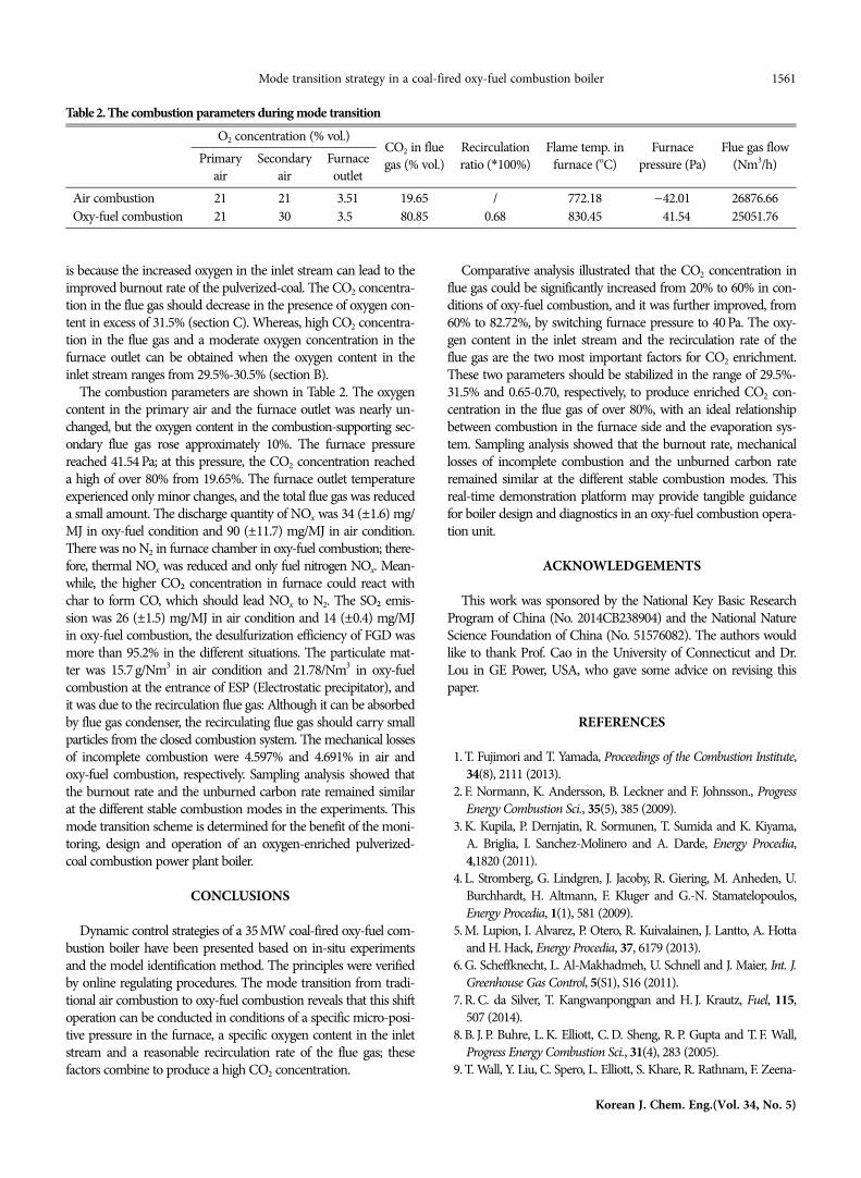
The combustion parameters are shown in Table 2. The oxygencontent in the primary air and the furnace outlet was nearly un-changed, but the oxygen content in the combustion-supporting sec-ondary flue gas rose approximately 10%. The furnace pressurereached 41.54 Pa; at this pressure, the CO2 concentration reacheda high of over 80% from 19.65%. The furnace outlet temperatureexperienced only minor changes, and the total flue gas was reduceda small amount. The discharge quantity of NOx was 34 (±1.6) mg/MJ in oxy-fuel condition and 90 (±11.7) mg/MJ in air condition.There was no N2 in furnace chamber in oxy-fuel combustion; there-fore, thermal NOx was reduced and only fuel nitrogen NOx. Mean-while, the higher CO2 concentration in furnace could react withchar to form CO, which should lead NOx to N2. The SO2 emis-sion was 26 (±1.5) mg/MJ in air condition and 14 (±0.4) mg/MJin oxy-fuel combustion, the desulfurization efficiency of FGD wasmore than 95.2% in the different situations. The particulate mat-ter was 15.7 g/Nm3 in air condition and 21.78/Nm3 in oxy-fuelcombustion at the entrance of ESP (Electrostatic precipitator), andit was due to the recirculation flue gas: Although it can be absorbedby flue gas condenser, the recirculating flue gas should carry smallparticles from the closed combustion system. The mechanical lossesof incomplete combustion were 4.597% and 4.691% in air andoxy-fuel combustion, respectively. Sampling analysis showed thatthe burnout rate and the unburned carbon rate remained similarat the different stable combustion modes in the experiments. Thismode transition scheme is determined for the benefit of the moni-toring, design and operation of an oxygen-enriched pulverized-coal combustion power plant boiler.
CONCLUSIONS
Dynamic control strategies of a 35 MW coal-fired oxy-fuel com-bustion boiler have been presented based on in-situ experimentsand the model identification method. The principles were verifiedby online regulating procedures. The mode transition from tradi-tional air combustion to oxy-fuel combustion reveals that this shiftoperation can be conducted in conditions of a specific micro-posi-tive pressure in the furnace, a specific oxygen content in the inletstream and a reasonable recirculation rate of the flue gas; thesefactors combine to produce a high CO2 concentration.
Comparative analysis illustrated that the CO2 concentration influe gas could be significantly increased from 20% to 60% in con-ditions of oxy-fuel combustion, and it was further improved, from60% to 82.72%, by switching furnace pressure to 40 Pa. The oxy-gen content in the inlet stream and the recirculation rate of theflue gas are the two most important factors for CO2 enrichment.These two parameters should be stabilized in the range of 29.5%-31.5% and 0.65-0.70, respectively, to produce enriched CO2 con-centration in the flue gas of over 80%, with an ideal relationshipbetween combustion in the furnace side and the evaporation sys-tem. Sampling analysis showed that the burnout rate, mechanicallosses of incomplete combustion and the unburned carbon rateremained similar at the different stable combustion modes. Thisreal-time demonstration platform may provide tangible guidancefor boiler design and diagnostics in an oxy-fuel combustion opera-tion unit.
ACKNOWLEDGEMENTS
This work was sponsored by the National Key Basic ResearchProgram of China (No. 2014CB238904) and the National NatureScience Foundation of China (No. 51576082). The authors wouldlike to thank Prof. Cao in the University of Connecticut and Dr.Lou in GE Power, USA, who gave some advice on revising thispaper.
REFERENCES
1. T. Fujimori and T. Yamada, Proceedings of the Combustion Institute,34(8), 2111 (2013).
2. F. Normann, K. Andersson, B. Leckner and F. Johnsson., ProgressEnergy Combustion Sci., 35(5), 385 (2009).
3. K. Kupila, P. Dernjatin, R. Sormunen, T. Sumida and K. Kiyama,A. Briglia, I. Sanchez-Molinero and A. Darde, Energy Procedia,4,1820 (2011).
4. L. Stromberg, G. Lindgren, J. Jacoby, R. Giering, M. Anheden, U.Burchhardt, H. Altmann, F. Kluger and G.-N. Stamatelopoulos,Energy Procedia, 1(1), 581 (2009).
5. M. Lupion, I. Alvarez, P. Otero, R. Kuivalainen, J. Lantto, A. Hottaand H. Hack, Energy Procedia, 37, 6179 (2013).
6. G. Scheffknecht, L. Al-Makhadmeh, U. Schnell and J. Maier, Int. J.Greenhouse Gas Control, 5(S1), S16 (2011).
7. R. C. da Silver, T. Kangwanpongpan and H. J. Krautz, Fuel, 115,507 (2014).
8. B. J. P. Buhre, L. K. Elliott, C. D. Sheng, R. P. Gupta and T. F. Wall,Progress Energy Combustion Sci., 31(4), 283 (2005).
9. T. Wall, Y. Liu, C. Spero, L. Elliott, S. Khare, R. Rathnam, F. Zeena-
Table 2. The combustion parameters during mode transitionO2 concentration (% vol.)
CO2 in fluegas (% vol.)
Recirculationratio (*100%)
Flame temp. infurnace (oC)
Furnacepressure (Pa)
Flue gas flow(Nm3/h)Primary
airSecondary
airFurnaceoutlet
Air combustion 21 21 3.51 19.65 / 772.18 −42.01 26876.66Oxy-fuel combustion 21 30 3.50 80.85 0.68 830.45 −41.54 25051.76

1562 Z. Luo et al.
May, 2017
thal, B. Moghtaderi, B. Buhre, C. Sheng, R. Gupta, T. Yamada, K.Makino and J. Yu, Chem. Eng. Res. Design, 87(8), 1003 (2009).
10. K. Andersson, R. Johansson, S. Hjartstam, F. Johnsson and B. Leck-ner, Experimental Thermal and Fluid Science, 33(1), 67 (2008).
11. C. Lupianez, I. Guedea, I. Bolea, L. I. Díez and L. M. Romeo, FuelProcessing Technol., 106, 587 (2013).
12. B. Leckner and A. G. Barea, Appl. Energy, 125, 308 (2014).13. Y. Tan, E. Croiset, M. A. Douglas and K. V. Thambimuthu, Fuel,
85(4), 507 (2005).14. M. Pottmann, G. Engl, B. Stahl and R. Ritter, Energy Procedia, 4,
951 (2011).
15. D. Snarheim, Control Issues in Oxy-fuel Combustion, NorwegianUniv. of Sci. and Technol. (2009).
16. I. Guedea, I. Bolea, C. Lupianez, N. Cortés, E. Teruel, J. Pallarés,L. I. Díez and L. M. Romeo, Energy Procedia, 4, 972 (2011).
17. K. J. Kuczynski, F. D. Fitzgerald, D. Adams, F. H. M. Glover, V. White,H. Chalmers, O. Errey and P. Stephenson, Energy Procedia, 4, 2541(2011).
18. P. J. Edge, P. J. Heggs, M. Pourkashanian, P. L. Stephenson and A.Williams, Fuel, 101, 234 (2012).
19. B. Jin, H. Zhao and C. Zheng, Int. J. Greenhouse Gas Control, 30,97 (2014).