A MNTI-ILY DICE RADIO - americanradiohistory.com · THE superhet receiver differs in many respects...
40
A MNTI-ILY DICE T OF RADIO AND ALL1EI7 MAINTENÂN'I PER COPY 15 CENTS He likes Physics ... (See page 50) FEBRUARY 1933 www.americanradiohistory.com
Transcript of A MNTI-ILY DICE RADIO - americanradiohistory.com · THE superhet receiver differs in many respects...

A MNTI-ILY DICE T OF
RADIO AND ALL1EI7 MAINTENÂN'I
PER COPY
15 CENTS
He likes Physics ... (See page 50)
FEBRUARY
1933
www.americanradiohistory.com

SERVILE BOOKS By JOHN F. RIDER
RADIO SERVICE QUESTIONS AND ANSWERS (2 Volunce«)
H ERE are two volumes which strike right to the bottom of your servicing operations! RADIO SERVICE QUESTIONS AND ANSWERS (2 Volumes) is a compilation of radio
service questions and answers as compiled over a period of years by Rider. Your problems .¢® and the solutions and the problems and solutions submitted to thousands of other Service
Rlo J¢r I Men are placed at your disposal.
ors RADIO SERVICE QUESTIONS AND ANSWERS (2 Volumes) covers all types of radio receivers, [Wiens speakers, tubes, amplifiers, power packs, public address systems-everything with which you
Qü ¢y$ as a Service Man may come in contact.
as d EF
These two volumes contain no theory.... Everything is narrowed down to practical IJ 5NFFw information-right to the point-and clearly explained.... No wasted words.
Here are two books which you can place into use the day they reach your hands. At no i / time do they become obsolete. Year after year you will be able to find data of value-of
Z / immediate financial return-information which will save your time-your effort. One answer in this series may bring you enough of a return to repay the total cost of both volumes.
The value of these two volumes is found in the fact that they cover old and new systems alike. Questions about old type tubes and the latest pentodes are included-the old receivers as well as the new receivers-the old elimin- ators as well as the new power packs-the old speakers as well as the permanent magnet type dynamics.
Type set; well illustrated; cloth bound. Sold with a Money -Back Guarantee. PRICE VOLUME No. 1, $1.00 POSTPAID. PRICE VOLUME No. 2, $1.00 POSTPAID.
SERVICING RECEIVERS by means of RESISTANCE MEASUREMENT
203 pages; type
SarviclIin9 II
Sur¢rh¢¢rodyn¢s bÿ
//
J.1s F. FIGER
set;
problem-simply combinations.
Type set; bound in cloth cover; 163 pages; profusely illustrated. Sold with. a Money -Rack Guarantee. PRICE $1.00 POSTPAID
Buy from Your Local Dealer or Use This Coupon.
RESISTANCE measurement as the basis for service operations offers many advantages. It removes the various disadvantages which are associated with voltmeter and current
meter methods of analyzing troubles. The reason for this statement is that, the ultimate test in every radio receiver is resistance measurement. Accordingly it is most logical to start right in with such measurement and save a great deal of time and guesswork.
Of course the voltmeter will still have its uses in connection with servicing-but resis- tance measurement is gradually becoming the basis for radio service operations.
SERVICING RECEIVERS BY MEANS OF RESISTANCE MEASUREMENT has been written to explain just how this method is applied. The contents of this book is of extreme value because it explains the usual resistance networks in receivers and thus prepares you for service oper- ating methods which recognize no limitations. When you cheek a receiver by measuring the resistance between any two points you can immediately locate the unit at fault-and thus eliminate all waste of time-all but one tolerance, namely that of the resistances. When you understand how this method can be applied-it is possible to locate the trouble in a radio receiver without removing the chassis from the cabinet.
cloth bound; well illustrated. Sold with a Money -Back Guarantee. PRICE $1.00 POSTPAID.
SERVICING SUPERIIETERODYNES THE superhet receiver differs in many respects from the conventional tuned radio fre-
quency type of receiving system. If you take service work seriously-it is absolutely essential that you be familiar with each and every type of superheterodyne-with each and every difference between this receiver and the t -r -f receiver. Yon actually owe this type of information to yourself-because you are earning your own livelihood at your own expense.
SERVICING SUPERHETERODYNES tells you just what you should know about this type of receiver and more so. It gives you all valuable information in a language which you can understand. There is nothing left to guesswork. As a matter of fact, it takes into consider- ation special circuits employed by the different receiver manufacturers.
Each type of receiver receives special discussion and description. Then the difference between the superhet and the t -r -f receiver is considered. This is followed by a complete breakdown of the receiver so that you learn to understand the workings of the different tubes and sections of the finished receiver. With this information in your possession, the exact type of superheterodyne receiver which you must service does not present any
because you know the function of the different parts and you can easily understand the different
RADIO TREATISE CO., INC., 1440 BROADWAY, NEW YORK, N. Y.
Enclosed find $ . Please rush, postpaid, the following books:
Radio Service Questions and Answers, Volume 1. ($1).
Radio Service Questions and Answers, Volume 2. ($1).
Servicing Receivers by Means of Resistance Measure- ment. ($1). Servicing Superheterodynes. ($1I.
NAME
ADDRESS
CITY STATE
SAY You SAW IT IN SERVICE
www.americanradiohistory.com

Oscillator, Tubechecker, An- alyzer. For Analyzer method.
Oscillator, Volt - Ohmmeter, (rapacity Meter. For Pninh[o-
Point method.
Profit Producing Service Kits See Them at Your Jobbers
CONVENIENCE and accuracy have been combined in these two mod-
ern combinations of Weston Standard- ized Service Units. They are business builders. Either combination quickly and surely gets at the root of the trouble.
For the ANALYZER-TUBECHECKER
method Weston offers the combination of Model 660 Analyzer, Model 661 Tubechecker and Model 662 Oscilla- tor. For those preferring the POINT-
TO-POINT method, Model 663 Volt- Olun1neter, Model 664 Capacity Meter and Model 662 Oscillator provide the ideal combination.
Every service man should get all the facts about these two combinations of Standardized Service Units. Mail the coupon for complete information.
Weston Electrical Instrument Cor- poration, 604 Frelinghuysen Avenue, Newark, New Jersey.
WH; STQN.TEti'ELL
Model 677 We- ton Tube Seller.
FEBRUARY, 1933
"u l41 :rt
U L 1 1 iJ 1J J
Rd/0 Ins/ruin en/s
Pattern 540 Port. able Tulle Seller.
WESTON ELECTRICAL INSTRUMENT CORPORATION 604 Frelinghuysen Ave., Newark, N. J.
Name
Address
Please send me further information on Weston -Jewell Service Equipment.
SAY YOU SAW IT IN SERVICE 43
www.americanradiohistory.com
FEBRUARY, 1933 Vol. 2, No. 2
SERVICE A Monthly Digest of Radio and Allied Maintenance
EDITOR John F. Rider
MANAGING EDITOR M. L. Muhleman
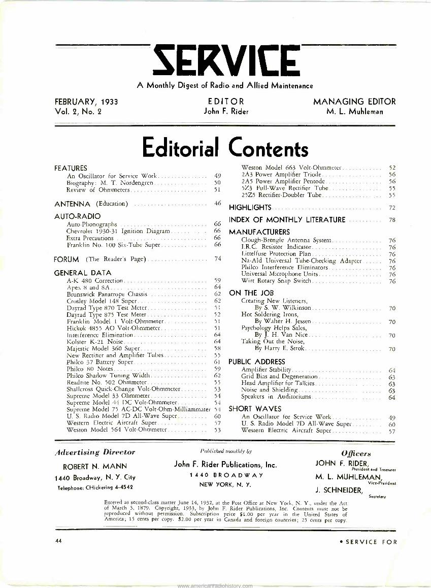
Editorial Contents FEATURES Weston Model 663 Volt -Ohmmeter 52
An Oscillator for Service Work 49 2A3 Power Amplifier Triode 56 Biography: M. T. Nordengren 50 2A5 Power Amplifier Pentode 56
Review of Ohmmeters 51 5Z3 Full -Wave Rectifier Tube 55 25Z5 Rectifier -Doubler Tube 55
ANTENNA (Education) 46 HIGHLIGHTS 72
AUTO -RADIO Auto -Phonographs 66
INDEX OF MONTHLY LITERATURE 78
Chevrolet 1930-31 Ignition Diagram 66 MANUFACTURERS Extra Precautions 66 Clough-Brengle Antenna System 76 Franklin No. 100 Six -Tube Super 66 I.R.C. Resistor Indicator 76
Littelfuse Protection Plan 76 FORUM (The Reader's Page) 74 Na-Ald Universal Tube -Checking Adapter 76
Philco Interference Eliminators 76 GENERAL DATA Universal Microphone Units 76
A -K 480 Correction 59 Wirt Rotary Snap Switch 76 Apex 8 and 8A 64 Brunswick Panatrope Chassis 62 ON THE JOB Crosley Model 148 Super 62 Creating New Listeners, Dayrad Type 870 Test Meter 51 By S. W. Wilkinson 70 Dayrad Type 875 Test Meter 52 Hot Soldering Irons, Franklin Model 1 Volt -Ohmmeter 51 By Walter H. Jessen 70 Hickok 4855 AO Volt -Ohmmeter 51 Psychology Helps Sales, Interference Elimination 64 By J. H. Van Nice 70 Kolster K-21 Noise 64 Taking Out the Noise, Majestic Model 360 Super 58 By Harry E. Strok 70 New Rectifier and Amplifier Tubes 55 Philco 37 Battery Super 61 PUBLIC ADDRESS Philco 80 Notes 59 Amplifier Stability 64 Philco Shadow Tuning Width 62 Grid Bias and Degeneration 63 Readrite No. 502 Ohmmeter 55 Head Amplifier for Talkies 63 Shallcross Quick -Change Volt -Ohmmeter 53 Noise and Shielding 63 Supreme Model 33 Ohmmeter 54 Speakers in Auditoriums 64 Supreme Model 44 DC Volt -Ohmmeter 54 Supreme Model 75 AC -DC Volt-Ohm-Milliammater 54 SHORT WAVES U. S. Radio Model 7D All -Wave Super 60 An Oscillator for Service Work 49 Western Electric Aircraft Super 57 U. S. Radio Model 7D All -Wave Super 60 Weston Model 564 Volt -Ohmmeter 53 Western Electric Aircraft Super 57
_1cluertising Director
ROBERT N. MANN
1440 Broadway, N. Y. City
Telephone: CHickering 4-4542
Published monthly by
John F. Rider Publications, Inc.
1 440 BROADWAY NEW YORK, N. Y.
Officers JOHN F. RIDER,
President and Treasurer
M. L. MUHLEMAN, Vice -President
J. SCHNEIDER, Secretary
Entered as second-class matter June 14, 1932, at the Post Office at New York, N. Y., under the Act of March 3, 1879. Copyright, 1933, by John F. Rider Publications, Inc. Contents must not be reproduced without permission. Subscription price $1.00 per year in the United States of 'America; 15 cents per copy. $2.00 per year in Canada and foreign countries; 25 cents per copy.
44 SERVICE FOR
www.americanradiohistory.com
In All the World No Unit Like This
Low -Priced Volt -Ohm -Meter
Model 4855 A.O.
NEW-ALL NEW!
READABLE One Ohm to a Million and Up to Ten Million
One Volt to Six Hundred (D. C.)
with
Special Leads to Insert into Tube Sockets
RUGGED For Lasting Service
KNIFE-EDGE POINTER,
For Easy and Accurate Reading
APPROVED GUARANTEED
Laboratory Accuracy
C. VOLTMETER HESI TANCE 1333 OHMS PER VOLT
Size 41/" x 7" x 31/" high
Large size meter, accurately calibrated, 31/4" body diameter, 41/4" flange, bakelite case, finished in two -stone walnut. Re- sistance, 1,333 ohms per volt. Accuracy 1%-All parts of the highest type possible to build. Scale ranges are: Volts: 0-3, 0-30, 14-300, 0.600 D.C. Ohms: 0-10,000, 0-1,000,000. Readable from one ohm to one million and up to ten million. Mounted in metal case, black velvet finish, with bakelite panel and meter flange finished in two-tone walnut, with bind- ing posts, knobs, etc., to match. Handsomely trimmed in chrome and provided with voltage adjuster to calibrate meter to batteries. Model 4855 A.O., as shown: List price $39.00. Net to Dealers and Service Men $23.40. Also furnished in Kit of all parts with full instructions, less case, binding posts and leads as Model 4844 A.O. Knock - Down Kit (not shown). List price $30.00. Net to Dealers and Service Men 318.00. Order special resistor to read 10 megs. Dealers' net price $1.50 extra. Prices west of Denver slightly higher.
THE HICKOK ELECTRICAL INSTRUMENT CO. 10514 DUPONT AVENUE CLEVELAND, OHIO
FEBRUARY, 1933 SAY You SAW 1T IN SERVICE 45
www.americanradiohistory.com

THE ANTENNA ... EDUCATION
LT'S talk about service instruments. The first thing we
are going to do, is to push the use of oscillators. There are altogether too many Service Men and organizations functioning in the service field without adequate test oscil-
lator apparatus. Whether you build or buy-the fact re-
mains that you need such equipment and you're going to need it more and more each day. The days of "hit and miss" methods of servicing are gone. Yes, you still come in contact with some of the old and simple receivers but the public is asking for better work-faster operation. To accom-
plish these two ends, without any reference to the problems of the more recent receivers, you must have the proper test equipment. Analyzers, diagnometers, set testers, ohm- meters, tube checkers, etc., are selling aplenty, but the use of oscillators has not reached its proper proportions. Once again, whether you buy or build, bear in mind that you need an oscillator.
NOW for a few words about technical knowledge. Be-
yond all doubt, the service field can use more advanced radio information. By this we do not mean an engineering education. Far from it. There is a wide gulf between a
thorough grounding in the art of radio as applied to radio receivers and related service work and design engineering knowledge. What we class as a thorough grounding is a
good knowledge of the fundamentals sufficiently well ab-
sorbed so that it can be interpreted into the reasons for the use of apparatus in the manner they are commonly employed, and sufficiently well absorbed so that the power of analysis as related to radio receiver problems in general is developed to its proper extent. By power of analysis we are not referring to service analysis only. We are vitally concerned with the ability to view a problem from various angles-with the ability to correlate all associated consider- ations; with the ability to recognize cause and effect and to apply this knowledge to the servicing of a radio receiver or associated apparatus.
With this in mind, it is the intention of the editors of SERVICE to present radio information in a manner which will be of definite value to each and every man who is interested in augmenting his scope of radio knowledge. No, it shall not be in the form of a course. . TALKING about schools, we cannot help but reiterate a
statement made by the writer during the recent I.R.S.M. Convention in Chicago. The time has arrived when the educational forces functioning in the radio industry must consider the present members of the radio service group and cease enticing new men from other non-competitive fields by presenting a glamorous picture of the possibilities to be found in the radio service field. Money can be made in the service field-perhaps not so much today, but it will be there
in the future. However, that money should go to the men now in the field-to the individuals who have been plugging and fighting for their existence during these troublesome days.
The service field is overcrowded. There is no more room for new men. There is plenty of room for educational activities by the radio schools now in existence, but these activities should be devoted to the improvement of the men now actively engaged in service work. In plain words, there is plenty of room for reasonably advanced courses offered to the experienced Service Man. Some schools are making such offers and the rest should fall in line.
The extent of the sales of radio receivers during the past decade is not great enough to absorb all of the men now associated with the service field. More new men will harm rather than benefit those in the field-those just entering and the industry itself. As a matter of fact the schools them- selves will suffer because the graduates will be unable to secure employment. We recognize that the schools have financial investments which they wish to keep intact. How- ever, there is every danger of sinking rather than saving the ship by augmenting an already overcrowded field. It is our opinion that the service industry as a body will support ad- vanced courses and those schools offering advanced courses, rather than those which offer both.
CHECK this issue closely. We are proud of the fact that we can give so much information relative to point-to-
point resistance measurement. This method of service an- alysis is growing by leaps and bounds. Each day we hear of another receiver manufacturer embarking upon the produc- tion of service data along resistance measurement lines. RCA in their 60 Series manuals and the makers of Majestic re- ceivers pioneered in such manuals, although it is true that RCA changed the structure of their manuals by omitting continuity test data, (which is the way they showed point-to- point data) and now show the d -c. resistance of every in- ductor and resistance. Majestic is continuing, as a matter of fact going a step further. Recent service data received by this magazine shows the entire Majestic manual predicated upon resistance analysis. U. S. Radio and Television are also going in for such work. The Clarion manuals, published by the Transformer Corporation of America, likewise give point-to-point data. Philco, Fada, Howard and many other receiver manufacturers are swinging into line.
One pertinent item has been brought to our attention. This is the necessity for the statement that tolerance values must be recognized when applying the point-to-point re- sistance measurement method of analysis. We take this opportunity of mentioning this fact in this editorial because it is the opening gun in the campaign and because it will be spoken of consistently.
John F. Rider.
46 SERVICE FOR
www.americanradiohistory.com

,4:.
iiludl!mi
NEWS AND VIEWS FOR SERVICE MEN AND DEALERS
from
NATIONAL UNION RADIO CORP. of N. Y.
400 Madison Avenue New York City
i / fism, :144; 1,i\...,7
NATIONAL UNION RADIO TUBES THE STANDARD TUBES FOR STANDARD SETS AT STANDARD PRICES
VOLTAGE DOUBLED BY TYPE 25Z5 RECTIFIER
NATIONAL UNION LABORATORIES DESCRIBE TUBE-NEW CODING
Among the many tubes developed in the National Union Laboratories during the past few months, the 25Z5 is of particular interest because of its unusual adapt- ability and applications. Type 25Z5 was brought from the laboratory stage and put into regular production in National Union factories late in January. The recent trend toward transformerless radio receivers of either the universal or A.C. operated type occasioned the development of the tube. It is a full wave, high vacuum rectifier of the heater cathode type for use in circuits especially designed to supply D.C. power from an A.C. power line.
In universal type receivers, the 25Z5 may be + used as a half wave rectifier, while in the A. C. operated type it may be used as a voltage doubler. In the latter application it provides about twice the D. C. output voltage obtainable from the half wave arrangement. The ready adaptability of the 25Z5 to two -fold application is made possible by the means of a separate base pin for each cathode. To facilitate its economical operation in series with the heat- ers of other tubes in the radio set, the heater of the 25Z5 has been specially designed. The construction of a receiver having reduced heat dissipation in the fixed series resistor has been made possible by the employment of a 25 -volt heater. Further, close electrode spacing and high rectifying efficiency are provided in the heater cathode design. The minimum of space for installation is re- quired as the 25Z5 is constructed compactly in a small, dome -top bulb.
TENTATIVE RATING AND
CHARACTERISTICS Heater Voltage Heater Current AC Plate Voltage
Plate (RMS) DC Load Current Maximum Overall
Length Maximum Diameter Bulb Base
per
25 Volts 0.3 Ampere
125 max. Volts 100 max. Milliamperes 41% 1 9/16" ST -12 Small 6 -Pin
1NEW TYPE NUMBER SYSTEM It is interesting to note that the 25Z5 has been assigned this type number under the new offi- cially recognized system of numbering tubes. Briefly, this system will operate as follows :
In the new type designation there will be a numeral or numerals followed by a letter of the alphabet and then followed by another numeral. The numeral before the letter gives us a clue to the filament voltage of the tube, 25 for in- stance, indicating that the 25Z5 is a 25 -volt tube. The letter "Z" indicates that the tube is a rectifier as rectifier types will be lettered from the end of the alphabet and detectors and amplifiers lettered from the beginning of the alphabet. The number after the letter indicates the number of usable elements in the tube, 5 in the case of the 25Z5 in spite of the fact that there are 6 -pin connections on this particular tube. (The filament of the tube as one of the usable elements is necessarily brought out in 2 - pin connections.) This system will not affect tube types already numbered but will apply to new types developed.
FEBRUARY, 1933 0
If this brief description is not clear National Union will gladly supply further information upon request.
SEATTLE SERVICE MANAGER LAUDS NATIONAL UNION
Alert to the savings made possible through National Union's Free Equipment offers, Fred P. Price Radio Service of Seattle, Washington. has seized the opportunity to take advantage of a number of deals. In a recent letter, Mr. E. R. Rice, Service Manager of this progressive organization, states: "As your records will show, we have Service Manuals Vol. 1 and Vol. 11, National Union Oscillator, 1,000 Tester and Unameter. We find them all valuable in our service work. We would like to express our appreciation of Na- tional Union's attitude in helping the service man with these service aids. As a whole, we find the quality of National Union tubes unsur- passed." This is an example of the way thousands of live wire service men throughout the country are tying up with National Union for profit. Service men who would be leaders in their community in intelligent service work must be well equipped. National Union makes necessary equipment avail- able at no cost.
BENCH KIT FREE! No need to play hide and seek with nuts, bolts, screws, resistors and other small radio parts when you own this handsome, sturdy, metal parts box.
This box was manufac- tured specially for Na- tional Union by one of the country's leading
steel companies. It is beautifully finished in green and golden yellow and contains 31 com- partments scientifically arranged. Don't let elusive parts waste your time and hold you up on jobs. National Union gives you this metal parts con- tainer, Free, no deposit, with a small purchase of National Union tubes. Write for complete details at once.
Ask Your Jobber's Salesman
SAY You SAW IT IN SERVICE
SAVE MONEY-GET FREE EQUIPMENT Of course you need modern equipment to carry on an intelligent profitable service business. Conserve your cash. Don't invest money in expensive equipment when you can own it without cost-the easy National Union way. Which of the items listed below do you need T
They are Free-Get details. Send coupon.
TWO SERVICE MANUALS by John F. Rider: Volume I-more than 2000 diagrams -1000 pages. Includes chassis wiring diagrams, voltage data, electrical values, color coding, socket layouts, peculiarities of radio receivers, etc. Volume II- absolutely non -duplicating. Over 700 pages cov- ering new sets up to 1932 Radio Show. Point to Point resistance data. Each in handsome green imitation leather, gold stamped binder. Free with small tube purchase.
READRITE TUBE TESTER: For home or store tube testing. Efficient. Neat. Compact. Fabri- coid covered case. Pilot light illuminates dial. Free with small tube purchase. Small deposit.
OSCILLATOR AND OUTPUT METER: Full broadcast range plus intermediate frequency range covered by leading types of superhets. Rugged construction. Sturdy fabricoid covered carrying case. Free with small tube purchase and small deposit.
THE UNAMETER: Most modern tube tester. Tests over 60 types. No adaptera. Dials scaled in color. Easy reading. Fool -proof meter pro- tection. Finished in gold and colora. Efficient convincing tests. Portable or Counter modela. Free with small tube purchase and deposit.
THE READRITE 1000 TESTER: Precision in- strument designed for newest method of testing continuity, capacity and voltages without pulling chassis. Teats through set sockets the resistance of voltage dividers, series resistors, transformer primaries-secondaries, filter chokes, speaker fields, capacities paper -mica type condensera, voltage of tube circuits. Valuable asset for profitable service work. Free with tube purchase and deposit.
HICKOK OHM CAPACITY -VOLTMETER: Ac- curate thorough testa of component parts of a radio set old, new or future modela. Testa con- tinuity of circuits. Resistance up to 80 megohms. D. C. Voltages up to 600 volts. Capacity of electrolytic and paper condensera up to 15 Mfd. Leakage or dielectric strength of paper con- densers and insulation. FREE with tube pur- chase and deposit.
NATIONAL UNION RADIO CORP. OF N.Y. 400 Madison Avenue, New York City Sirs: I am interested in following equip- ment: Readrite Tube Tester Oscillator & Output Meter D Readrite Resistance Tester D Volume I [3 Volume II Unameter D Ohm Capacity Bench Kit
S2
NAME
ADDRESS
CITY STATE
47
www.americanradiohistory.com

PROTECT -O -PACKED RESISTORS
10 GOOD REASONS WHY YOU SHOULD "SERVICE" WITH OHIOHMS
Accuracy-resistance value within 10% tolerance. Permanency-value unchanged by age. Absence of noise.
Low Heat Coefficient. Freedom from Capacity Effect.
Unaffected by Humidity. Low Voltage Coefficient. Mechanical Strength-ability to withstand rough handling. Appearance-straight wire leads, good paint finish, etc. Color Coded, Printed Values, Trade -Marked.
SPARK SUPPRESSOR SETS For eliminating ignition interference on radios installed in Automobiles.
Sets are furnished for 4, 6 and 8 cylinder cars.
Furnished complete with Condenser designed to
withstand unusual conditions of temperature and
vibration ... also, necessary spark suppressors
48
enclosed within glazed porcelain tube eliminating
accumulation of dirt. Made of special non -moisture
absorbing material to prevent shorting. The life
of an Ohiohm Suppressor is the life of the car.
Every Radio Customer a Prospect for CLEANAIRE Refrigerator Deodorizer
Absorbs and destroys food odors. Prevents blending of flavors and tainted foods.
Add this to your line ... excep- tional profit .. .
WRITE FOR FACTS
THE OHIO CARBON COMPANY 12502 BEREA ROAD CLEVELAND, OHIO
Ohiohms are made in Canada by C. C. Meredith, Ltd., 639 Bay St., Toronto
SAY You SAW IT IN SERVICE SERVICE FOR
www.americanradiohistory.com

An Oscillator for Service Work N oscillator to be used for service work must meet a
number of special requirements. Of these require- ments, portability, convenience and stability are
probably the major points. Of secondary importance, but still quite necessary, are wide frequency coverage, satisfac- tory modulation, proper attenuation, and the elimination of interference with the test signal generated by the oscillator.
In designing the oscillator to be described, the above points were taken into consideration and were met as fol- lows:
Portability was gained by the use of a type 30 tube which requires little in the way of "A" current and will oscillate satisfactorily with but 221/2 volts on the plate. This permits including both the "A" and "B" batteries within the case
without sacrificing compactness. At the same time, the point of possible interference is eliminated, as the oscillator is in no way coupled to the a.c- line supplying the radio receiver under test and consequently there can be no r -f. getting into the receiver through the power line and upsetting the alignment or adjusting procedure.
The oscillator is made convenient by its small weight and because a
change of frequency band is made by merely flipping a single switch mounted on the front panel. Its convenience is further added to by the fact that the oscillator will cover all the most important inter- mediate frequencies (150 kc. to 300 kc.) , the com- plete broadcast band of 550 kc. to 1500 kc. (actu- ally, about 540 to 1700 kc.) and by the use of harmonics, "short-wave" frequencies as high as 20,000 kc. (15 meters). More of this later.
The matter of stability was not so easily licked. First of all, we tried a resistance -stabilized circuit. This proved fine for any single frequency but was unreliable where a wide
sweep of frequencies had to be made. Electron -coupled oscillators were also tried, and these are quite satisfactory when a tube with a cathode is employed, but not so satis-
factory with a filament -type tube. We finally resorted to the good, old plate -tuned oscilla-
tor with a low L -C ratio; that is, a high -C circuit, wherein the capacity is large in comparison to the inductance. This proved entirely satisfactory and is used in this oscillator. It provides a better degree of stability than is ordinarily obtained and is therefore of value.
There is nothing new about the self -modulation scheme.
The tube is made to block at an audio -frequency rate by
the proper selection of capacity and resistance values for the grid condenser and leak, which in this case are connected in the low -potential end of the grid circuit.
FEBRUARY, 1933
One other important thing is the attenuator. This is a
100 -ohm variable resistance mounted in a metal case so that
no other shielding was necessary. It is self -shielded as it
stands. This attenuator provides very good control and
does not reduce the gain too rapidly. Yet a very low output
can be had, which is necessary for the sake of accuracy in
alignment, etc. A strong signal "spreads" too much and is
therefore unsatisfactory.
CONSTRUCTIONAL DETAILS
A photo of the complete oscillator is shown in Fig. 1.
The case is of aluminum and is 10 inches long, 6 inches
high and 71/2 inches deep. These measurements do not have
to be followed exactly, but a metal cabinet somewhere near
this size should be used.
Fig. 1. A view of the completed plate -tuned oscillator
The frequency selector dial is in the center of the front panel and might well be a vernier dial of the type which has blank white spaces near the bot- tom or sides so that cali- brations can be marked thereon. However, a dial of the type shown is per- fectly satisfactory if charts are made up for the fre- quency bands. It all de-
pends on which you like the best.
The frequency selector switch is on the left side of the front panel and this is marked S1 and S2 in the diagram. When switched to the right, the oscillator covers the broadcast band and the short-wave band by harmonics, and when
switched to the left covers the intermediate -frequency band. The toggle switch to the right of the dial makes and
breaks the filament circuit of the type 30 tube. On the top panel of the case is mounted the attenuator
control knob and directly behind this knob the three ter- minal posts for the oscillator output. The lead used on the "high side" of the output should be shielded. The shielding itself can be used as the grounded lead if desired, in which case only one cable will lead from the oscillator to the re- ceiver.
An inside view of the oscillator is shown in Fig. 2. The two "A" batteries and the "B" battery can be seen at the rear of the case. These should be fastened securely to the wooden baseboard so that at no time will they shift around.
In front of the batteries is the voltage regulator tube, marked R in the diagram. This is used to keep the fila-
ment voltage constant and in this manner adds to the stability of the oscillator.
Now note the two inductances. The "broadcast" induc- tance is by the side -of the "B" battery and is at right angles to the i -f. inductance.
49
www.americanradiohistory.com

Now let's look at the circuit diagram, shown in Fig. 3. r The switch S1 -S2 is all in one hunk, so to speak, and is really a triple pole, double pole affair. The S1 section per- I
mits a change -over from the plate broadcast coil L-1 to the I
plate i -f. coil L-2, while the S2 section does the same for L-3 and L-4. ,
CIRCUIT CONSTANTS
R-1 (fixed) 500,000 ohms C-3 (adjustable) R-2 (fixed) 1,000 ohms C-4 (adjustable) R-3 (variable) 100 ohms C-5 (paper) C-1 (variable) .0005 mfd. C-6 (paper) C-2 (mica) .0001 mfd. C-7 (mica)
.00003 mfd.
.00003 mfd. 0.5 mfd. 0.5 mfd.
.005 mfd.
¿34
I R2
-30
When the switch is thrown, it "throws" the variable con- 2 r1`'
denser C-1 with it, so that in one case C-1 tunes L-1 and in OUTPUTi R3
the other case it tunes L-2. But since L-2 has a large value] 3° ......
of inductance in comparison to the capacity of C-1, which L___i_i -
is .0005 mfd., we no longer have a high -C circuit. There- fore, the condenser C-2 is permanently shunted across L-2 to provide the large capacity we wish. This is a .0001-mfd. moulded bakelite mica condenser. Its value may wander a bit over a period of time but not sufficiently to cause trouble.
The blocking condensers C-5 and C-6 are necessary to keep the plate voltage from getting back to ground. The condensers C-3 and C-4 are also blocking condensers and are used to keep the plate voltage out of the feeder. These are small adjustable trimmer condensers each with a maxi- mum capacity of about .00003 mfd. or so. Turn the screw on C-3 all the way in and the screw on C-4 all the way out. Then, when using the oscillator, strap together terminals 1
and 2 for frequencies less than 500 kc., so that C-3 and C-4 are in parallel, and for frequencies higher than 500 kc., just use posts 2 and 3, the latter being the ground.
Now for the grid leak and condenser: R-1 and C-7 re- spectively. These units provide the self -modulation feature and it is desirable to have a rather high-pitched note as it has less tendency to spread. However, the note may be most any pitch you wish within reason and you can change it by altering the values of R-1 and C-7. In this oscillator C-7 has a value of .005 mfd. and R-1 a value of approxi- mately 500,000 ohms.
No matter what type of circuit is used, a self -modulated oscillator will change its pitch as the variable condenser is swung through its range. This change in audio pitch makes
Fig. 2. Interior view of oscillator, showing location of parts
50
LI IL2
S2
EL r--- }oL3 L4q
C7 RI i T
J Fig. 3. The schematic diagram of the oscillator. Parts values
are given in the table to the left
no difference in the operation of the oscillator unless the pitch happens to go so low as to "spread." In such an event the resistance value of the grid leak should be decreased and the lower the value of resistance here the less variation there will be in the audio pitch. At the same time the capacity of the grid condenser may be increased to provide the pitch most desired.
COIL DATA
The broadcast coils L-1 and L-3 are both wound on the same form. This form should be 2 inches in diameter and about 21/2 inches long. Bakelite tubing will do very nicely. Coil L-1 consists of 55 turns of No. 26 S.S.C. wire close wound and will come close to filling the length of the form. Coil L-3, which is the grid coil, consists of 20 turns of the same size wire either layer wound or scramble wound on a section of celluloid sheet fitting directly over coil L-1 so that
(Continued on page 68)
The Man on the Cover M. T. Nordengren
Service Manager, Grigsby-Grunow
AFTER Mr. Nordengren had completed his high school education, he delved into the problems of Physics
and Economics with great interest-but after a tough battle, Physics got the upper hand and led him into an Electrical Engineering University course.
And out of all this grew Mr. Nordengren's interest in radio. Off he went to the Western Electric Company and stayed there for the next four and a half years as Section Head of the Inspection Division on transformers, filters, repeating coils, etc. Then a year on Movietone equipment and sound projection.
With this experience and education behind him, he took a position with the Grigsby-Grunow Company, in 1928. He landed right in the Engineering Division as Product Analy- sis Engineer in the factory.
In November, 1931, he took the position of Service En- gineer of the Company, and a month later walked into the position of General Service Manager of the Radio Division, where he still reigns.
SERVICE FOR
www.americanradiohistory.com

General Data. .
REVIEW OF OHMMETERS Franklin Model 1 Volt -Ohmmeter
The Model 1 Voltmeter -Ohmmeter uses a single meter to cover the various voltage and resistance ranges, as shown in the accompany- ing photo.
YOlTA4t 3 COROLp5AT0R
Tw[ [RAwRLIR RADIO 003100, swro, rs.A.
F- l` 00
{3. f 390 0 e M$ VOLTS VOLTS
Panel view of the Franklin Model 1
Volt -Ohmmeter
The meter has a double scale; the upper scale reading 0-100,000 ohms; the lower scale reading 0-300 volts. The resistance can be reduced to one -tenth its value and the volt- age range can be reduced to 3 or 30 volts and increased to 600 volts. A high -range and low -range switch is mounted on the bakelite panel.
1000.0 PER VOLT 4.5 VOLT METER
OHMMETER
O O
000W 4.50
25,500-
270.000., 300.000"
© O O í30V í300V. í600V
Complete schematic diagram of the Franklin Model 1 Volt -Ohmmeter
FEBRUARY, 1933
When used as a voltmeter, the Model 1
has a resistance of 1,000 ohms per volt in each of its ranges, thereby measuring plate voltage without distortion of reading.
The 41/2 -volt dry cell to supply the voltage for the ohmmeter action is inclosed in the case. On the panel is a compensator adjustor to provide for zero reading.
The pin jacks for resistance and voltage readings are arranged along the front edge of the panel.
The complete circuit diagram of this in- strument is shown herewith.
Hickok Ohm Capacity Voltmeter For a description and circuit of the Hickok
Ohm Capacity Voltmeter, see the article on page 308 in the November issue of SERVICE.
Hickok 4855 AO Volt -Ohmmeter This unit, illustrated herewith, employs a
meter with a sensitivity of 1,333 ohms per volt. There are four voltage ranges of 0-3-30- 300 and 600 volts and two resistance ranges of 0-10,000 ohms and 0-1,000,000 ohms, the
SWITCH
01115AMP 125. W
/B6566ÿ 00075
2133.0 AMP
15V
- 9B94.0
9V
400.000. 360000.0 36000.
600 300 30 3 # VOLTS
RES.
0-500
The schematic diagram of the Hickok 4855 AO Volt -Ohmmeter. All values
are given
resistance range being readable from 1 ohm up to 1,000,000 ohms. Provisions are made so that with the addition of another cali- brated resistor, the readings can be carried up to 10,000,000 ohms.
The values of the resistors, etc., are given in the accompanying circuit diagram of the unit. The switch marked V, L, and H (Volts, Low Resistance Scale, High Resistance Scale) is the switch on the panel just to the left of the "Resistance" binding posts.
The voltage compensator or zero adjustor is mounted to the left of this switch and in the diagram is the 500 -ohm variable re- sistance connected in series with the batteries. The batteries are contained in the case of the instrument.
Along the front edge of the panel are the binding posts for voltage readings. These are marked with their respective values.
The meter used has a 27/8 -inch scale length, the entire meter diameter being 41/4 inches.
The Hickok 4855 AO Volt -Ohmmeter. The knob at the left is for battery
voltage adjustment
Dayrad Type 870 Test Meter The Dayrad 870, illustrated herewith, is
designed to provide a number of tests and operates from any 100 -130 -volt, 60 cycle line. The instrument uses a type 82 tube as the rectifier, as indicated in the accompanying diagram.
The following measurements and ranges are covered by the instrument:
Ohms; 0-1,000-5,000-50,000-500,000 and 0 to 5 megohms. D -C. Volts; 0-30, 0-300 and 0-600 volts at 1,000 ohms per volt. D -C. Milliamperes; 0-30 and '0-300. Microfarads; .05-.001, 5-.01 and 5.0-0.1 mfd.
Provisions are made so that the unit may also be used as an output meter for aligning receivers, etc.
Panel view of the Dayrad Type 870 Test Meter. The dome cap at the rear of the panel covers the rectifier tube
51
www.americanradiohistory.com

GENERAL DATA-continued
0o vo.Ts
'O
o X
b
2 2"
P
2520 11235. 19915'. 1J1.OST6119;9/.94
b b O O
'O
Schematic diagram of the Dayrad Type 870 Test Meter, which 110 -volt, 60 -cycle line. All values are given
The panel carries a selector switch for the various measuring ranges, a special a -c. line adjustor and a push button to be used when the line voltage is being adjusted to the meter.
The instrument is mounted in a cast alu- minum case.
Dayrad Type 875 Test Meter This instrument, illustrated herewith, is
somewhat similar to the Type 870 but is battery operated, two standard 221/2 -volt bat- teries and one 41/2 -volt battery being used. Compartment space for these batteries is pro- vided inside the cast aluminum case.
Ranges are selected by means of a rotary
3960
VOLTS
MA.
AV 00o. 10 00.11"
o 0 0 -fl -0
0 a
o ó
h - `y
Iv 1ouot 0 0 0 0
52
.,6 ,To .y..r...en
operates from the
Above: Panel view of the Dayrad Type 875 Test Meter.
Left: The sche- matic diagram of the same unit. This model is battery operated. The switches are shown in a straight line, though they are actually of the
rotary type
switch. The measurements possible, and the ranges, are as follows: Ohms; 0-3,000, 0-30,- 000, 0-300,000 and 0-3 megohms. D -C. Volts; 0-6, 0-30, 0-60 and 0-300 volts at 1,000 ohms per volt. D -C. Milliamperes; 0-6, 0-30, 0-60 and 0-300. D -C. Amperes; 0-30.
The instrument has a self-contained d -c. blocking condenser so that the unit may be employed as an output meter with adjustable sensitivity. The blocking condenser makes it possible to connect the meter directly to the plate terminal of the output tube in a radio receiver.
The meter has a zero adjustor knob on the panel.
Weston Model 663 Volt -Ohmmeter The Weston Model 663 Volt -Ohmmeter
shown in the accompanying illustration, uses a single meter with an indicating scale marked 0 -1,000 -ohms, 0-2.5-5-10 volts and milliamperes. The following ranges are avail- able: 0-5-25-250-2,500-25,000-250,000 ohms center scale; 0-200-1,000-10,000-100,000- 1,000,000 and 10,000,000 ohms full scale; 0-2.5-10-100-250-500 and 1,000 volts full scale at 1,000 ohms per volt. Also 0-1-5-25 and 100 milliamperes full scale at 500 milli- volts.
When used as an ohmmeter it will give a reading as low as 0.1 ohm, the first calibrated meter division being 0.2 ohm.
Jacks are provided on the left side of the moulded bakelite panel for voltage readings and on the right side of the panel for re- sistance readings.
In the center of the panel, below the meter, is the selector switch. When in the first or extreme left position, voltage and current readings can be taken. The remainder of the positions are for selecting the resistance ranges.
Front panel view of the Weston Model 663 Volt -Ohmmeter. The meter has scales for reading ohms, volts and
milliamperes in various ranges
'KM YOU- OHM MfTER MOOR 663
ic.45
:,:w,GArÉ
SERVICE FOR
www.americanradiohistory.com

GENERAL DATA-continued
RES. OHMS
O H- I tu«
MA. Q
1
4214.
5
e4.2r.
25 13.11 w
100
5.24.
5000
MODEL 600 50_A.a
2500 . XACT
223 0oe w
9 CELLS +-iiIIIIIIIIIIIIIIII
*4e.e + +S
i1.190.6. A' O
x,$ x10
Only one resistance range is actually shown on the instrument scale. The other five ranges are obtained by using the factor indi- cated, i.e., multiplying by 10,000 for the high range in one instance or dividing by 5
for the low range in another instance. These factors are indicated on the scale of the se- lector switch. These same factors are also included in the accompanying schematic dia- gram of the instrument, as well as the re- sistance values at each point. This is a worm's eye view diagram, that is, as it would appear from beneath the panel, the jacks and so on therefore being reversed in their positions.
The panel of the instrument also includes an ohmmeter adjustor so that zero adjustment can be made on the different resistance ranges.
The necessary dry cells for supplying volt- age fit into clips mounted on the back of the panel. The current drawn from the bat- teries and passing through the resistance being measured, is a maximum of 60 microamperes on ranges X x 10,000 and R x 1,000 and 600 microamperes on range R x 100. On range R x 10 the current drain is 6 milliamperes and on the direct range, 60 milliamperes. On the range R ± 5 the drain is 300 milliamperes. These maximum values occur at the zero ohms position on each range. The value of current at center scale would be one-half of the maximum value given in each case.
Weston Model 564 Volt -Ohmmeter This unit consists of a Model 301 meter
with four 1,000 ohms per volt voltage ranges of 0-3-30-300 and 600, two resistance ranges of 0-100,000 and 0-10,000 ohms.
A self-contained 41/2 -volt "C" battery is provided for potential. The battery adjustor, to provide zero scale adjustment, is directly below the meter on the panel, as shown in
2.5
-:50CIV 10
90 00o W
100
150e00w
25 0 250000. 500
500 000 w
1000
The schematic diagram of the Weston Model 663 Volt -Ohm- meter. The val- ue of each re- sistor is given as well as the vari- ous terminal markings which will be found on the panel of the instrument
the accompanying illustration. Any change in potential of the self-contained battery can be readily compensated for by short-circuiting the pin jacks marked X -X at the bottom of the panel, and then varying the voltage adjustor.
Panel view of the Weston Model 564 Volt - Ohmmeter. The right hand tog- gle switch alters the sensitivity of the meter when used as an
ohmmeter
All voltage ranges are brought out to pin jacks at the top of the panel. A toggle switch connects the meter in circuit as a voltmeter or ohmmeter. The instrument sensitivity, when used as an ohmmeter, may be changed by the toggle switch on the right side of the
Schematic diagram of the Weston Mod- el 564 Volt -Ohmmeter. Note the con- nections of the toggle switches in the
center
panel from 1 to 10 milliamperes when using the 100,000 or 10,000 ohm scale. This sim- plifies checking up trouble in high or low resistance circuits.
The values of the various resistors, and so on, are indicated in the circuit diagram re- produced herewith.
Shallcross Quick -Change Volt - Ohmmeter
This instrument, illustrated herewith, is designed to provide the essential voltage and resistance measurements encountered in ser- vicing work with minimum adjustments. A
h V
OHMS VOLTS
x, ,o
X10
I
l000
5100 CON TINVI ry
X
ExT.45V
100
500---- 00
I
Above: Dimensional drawing of the Shallcross Volt -Ohmmeter panel. Be- low: Circuit diagram of the Shallcross
job, including all resistance values
r-
-----
b
o o o
I M.A.
4470
J
FEBRUARY, 1933 53
www.americanradiohistory.com

GENERAL DATA-continued
single set of binding posts and a "quick - change' tap switch make it possible to select any of the following voltage or resistance ranges without the necessity of changing test leads to different binding posts or pin jacks: Voltage Ranges; 0-10-100-500 and 1,000 volts. Resistance Ranges; 2.5 to 3,000 ohms, 25 to 30,000 ohms, 250 to 300,000 ohms and 2,500 to 3,000,000 ohms. The last named
MO
Y ,
CD CON
IMO tMT 455 `
Panel view of the Shallcross Quick - Change Volt -Ohmmeter, all functions of which are controlled by a single
rotary switch
range is obtainable by connecting in series with the test leads an extra battery of 45 volts and by setting the selector switch to "X 1,000."
A Weston Model 301, 0-1 d -c. milliam- meter is used in this instrument. Its connec- tions and the values of the resistors used are shown in the accompanying schematic diagram.
Supreme Model 44 DC -Volt - Ohmmeter
The new Model 44 D -C. Volt -Ohmmeter, illustrated herewith, is an unusually compact instrument for voltage measurements, re -
Here is the Supreme Model 44 DC Volt - Ohmmeter, available in both shop and
portable models
sistance measurements and continuity tests. The Model 44 uses a self-contained flash- light battery for resistance measurements in
33^
two ranges, 0/1,000 and 0/100,000 ohms, and is provided with external connections, as shown in the diagram, for a 45 -volt bat- tery to increase its range to 1,000,000 ohms. Also, four d -c. voltage ranges of 0/10, 0/100, 0/250, 0/1,600 volts are available. The 44 is contained in a hardwood case and is avail- able in shop or portable models.
Supreme Model 75 AC-DC-Volt- Ohm-Milliammeter
The Model 75 provides six output meter ranges, six a -c. voltage ranges, 0/2.5/10/100/ 250/1,000 volts, six d -c. voltage ranges, 0/1, 0/2.5/10/100/250 volts, six d -c. milliampere ranges 0/1, 0/2.5/10/100/250 ma., two re- sistance ranges 0/5,000/500,000 ohms.
Left: The Supreme Model 75 AC - DC Volt - Ohm - Milliam- meter, which also may be used for a bridging test for condensers
All a -c. and d -c. current and voltage ranges are at a senstitivity of 1,000 -ohms -per -volt. High sensitivity of a -c. voltage and current ranges, 1,000 -ohms -per -volt, facilitates capac- ity measurements. All a -c. and d -c. voltage and current measurements are at same scale distribution, which simplifies readings.
The a -c. and d -c. milliampere ranges are protected with fuses for added protection in event of inadvertent overload. All measure- ments are within the standard accuracy tolerances.
Right: Schematic diagram of the Supreme Model 33 Ohmmeter. A 45 - volt battery can be added to extend the resistance range to one megohm
-Mc)ISVBAr. //IC6 0 /0004
3/,3003,q67^
3,2=e^ verlas
d
9,950^
-,000^
ON/Ys cO.y -
VOLT3 car- T3g 000 ^ /30,000-, 90 0004
050 V, /00V /O V
+tom
áOD,NG...
Circuit diagram of the Supreme Model 75 AC -DC Volt-Ohm-Milliammeter
Self-contained capacitor is very useful for bridging test of capicitors when suspected of being open circuited or of low capacity; many times found to be the condition of electrolytic capacitors.
Supreme Model 33 Ohmmeter The Model 33 Ohmmeter is a completely
self-contained instrument for resistance
-CQH. (ID
Left: Circuit dia- gram of the Su- preme Model 44 DC Volt - Ohm- meter. A double pole, double throw switch changes the readings from volts to ohms, or vice
versa
t45 V.
o-Se00,,
O-/OO OeO
O-/ME6.
Left: A panel view of the Supreme Model 33 Ohmmeter which has two resistance ranges, and by the use of a separate battery will read up to one
megohm
measurements and continuity tests. A large 31/2" bakelite case meter is employed, ac- curately calibrated in resistance ranges of 0/1,000 and 0/100,000 ohms, actuated by a self-contained flashlight battery. The Model
54 SERVICE FOR
www.americanradiohistory.com
GENERAL DATA-continued
33 is provided with external connections for a 45 -volt battery to extend its range to
1,000,000 ohms. A set of Supreme test leads are included in the equipment.
An illustration of the Model 33 Ohmmeter and schematic diagram are shown herewith.
Readrite No. 1,000 Resistance Tester For a description and circuit diagram of
the Readrite No. 1,000 Resistance Continuity and Capacity Tester, see the article on page 310 in the November issue of SERVICE.
Readrite No. 502 Ohmmeter The Readrite No. 502 Ohmmeter, shown in
the accompanying illustration, is a two -scale
resistance meter. The upper scale range is
0 to 10,000 ohms and the lower scale is 40 to 0 ohms.
Directly below the meter is the knob for zero adjustment. To the right of the knob are the three insulated jacks, one common, for the two ranges on the meter. Special cords
A view of the compact Readrite No. 502 Ohmmeter which has low -scale and
high -scale readings
are used to patch from one jack to another. The external connections are shown on this page, along with the circuit diagram.
New Rectifier and Amplifier Tubes RCA and Cunningham have announced
four new tubes which will immediately take their place in the design of new receivers. Two of these tubes are rectifiers and two are amplifiers.
First a word about the type numbers. The new rectifier tubes carry the numbers 25Z5 and 5Z3. These numbers have a particular significance which should not be overlooked, as more than likely this type of coding will be used from now on.
Now, in the case of the type number 25Z5, the letter Z indicates that the tube is a recti- fier. The number 25 means that the tube has a 25 -volt filament. The 5 following the Z means that the tube has five useful elements, counting the filament as one. Thus, when we come to the type number 5Z3, we know that the tube has a five -volt filament, that it is a rectifier and that there are three useful elements.
The two new amplifier tubes carry the type numbers 2A3 and 2A5. In both these cases 2.5 -volt heaters are used, but the 0.5 volt is
FEBRUARY, 1933
4.5v.
Circuit diagram of the Readrite
BIacK / so3
x Xß
11111111 1111111111
22.5v. 22.5v.
No. 502 Ohmmeter. The external connections are also shown
White
dropped from the coding in order to avoid confusion. The A brands each tube as an amplifier, and by looking at the numbers we know that one is a triode and the other a pentode, or something very similar.
Now, let's get down to the tubes them- selves.
THE TYPE 5Z3 HEAVY DUTY, FULL -WAVE
RECTIFIER
This tube is somewhat similar to the type '80 but will furnish approximately twice the d -c. load current at higher d -c. output voltages
ST SuLle
2ä; Lux
80,TC vICre Or BASE
Fig. 1. Details of the 5Z3 full -wave rectifier
and is therefore intended for supplying recti- fied power to radio receivers and amplifiers having very large direct -current requirements.
A sketch of the tube, giving the dimen- sions and base connections, is shown in Fig. 1. The tube fits the standard four -contact socket, but this does not mean that it should be plugged in in place of an '80. Don't do it.
The tentative rating and characteristics of this new rectifier are as follows: Filament Voltage (A -C) 5.0 Filament Current 3.0 Amps. A -C. Voltage
per Plate (RMS) 500 max. D -C. Output Current 250 max. MA.
This rectifier can be used with filter circuits of the condenser -input or choke -input type, but the filter circuits must be so designed as
to meet the current and voltage demands placed by the tube.
THE TYPE 25Z5 RECTIFIER -DOUBLER TUBE
This is an interesting tube because it is adaptable to the new crop of "transformer - less" receivers of either the "universal" type or the "a -c. operated" type. In "Universal" receivers the 25Z5 may be used as a half - wave rectifier, while in the "a -c. operated" type, it may be used as a voltage doubler to provide about twice the d -c. output voltage obtainable from the half -wave arrangement. Thus, operating directly from a 110 -volt a -c.
line, with no power transformer, output volt- ages from about 120 to approximately 260 may be had at the output, depending on the load or current drain of the receiver.
A sketch of this tube, with dimensions and base connections, is shown in Fig. 2. The tube fits the standard six -contact socket. A glance at Figs. 3 and 4 show that the tube has the usual two plates and a filament which is divided between two cathodes. The cathodes
wn> V. mmt.
II II_ ...32....1
.. c.,.;ag á :'> )
o.,oh, h. o. ,, Fig. 2. Details of the 25Z5 rectifier -
doubler tube
55
www.americanradiohistory.com

GENERAL DATA-continued
Fig. 3. The 25Z5 connected to func- tion as a half -wave rectifier
are independent of each other and connect to separate base prongs. When the tube is used as a half -wave rectifier the two plates are joined and the two cathodes are joined, as shown in Fig. 3. When the tube is used in a voltage doubler circuit, as shown in Fig. 4, these same elements are used separately.
The heater of this tube has been designed to facilitate its economical operation in series with the heaters of other tubes in the radio set. The employment of a 25 -volt heater per- mits the construction of a receiver having reduced heat dissipation in the fixed series resistor. Furthermore, the heater -cathode de- sign permits of close electrode spacing and provides high rectifying efficiency.
When the rectifier is used in the voltage - doubling circuit, each section functions as a half -wave rectifier and each section charges one of the condensers C (See Fig. 4). The two condensers in turn discharge through the load with the result that the voltage across the load is the sum of the d -c. output voltage of the tube and the discharge voltage of the condenser.
Like the full -wave circuit, the voltage - doubling circuit gives an output having a ripple frequency twice that of the supply line, or 120 cycles if the supply voltage is 60 cycles.
In using this circuit large condensers are
MEDIUM P-Pox PSE-
PiN 3- [PtEP
owP .roi1 noi oI.
'i}P M..
POTION, v.r DC MSC
nix 0-GRID
Fig. 5. Details of the 2A5 power amplifier pentode
necessary to give good regulation of the d -c. output voltage at higher values of load cur- rent ... in most cases from 8 mfd. to 16 mfd. However, these condensers need not have a high voltage rating as they have only to withstand the peak value of the a -c. supply.
The tentative rating and characteristics of the 25Z5 are as follows: Heater Voltage 25 Heater Current 0.3 Amp. A -C. Voltage
per Plate (RMS) 125 max. D -C. Load Current 100 max. MA.
No doubt this tube will find wide applica- tion in the near future.
TYPE 2A5 POWER AMPLIFIER PENTODE
This is a power amplifier pentode of the heater -cathode type for use in an audio out- put stage and is capable of giving a large output with a relatively small input signal voltage.
A single 2A5 in the output stage is capable of supplying about 3.0 watts, while two 2A5's in push-pull can deliver in excess of 6.0 watts.
Fig. 4. The 25Z5 connected to function as a voltage doubler
The power handling ability of the 2A5 is essentially the same as that of the 59 with pentode connection. The two types, however, are not directly interchangeable because of the difference in base connections. This will be apparent from the sketch of Fig. 5.
The tentative rating and characteristics of the 2A5 are as follows: Heater Voltage
(A -C. or D -C.) Heater Current Plate Voltage Screen Voltage Grid Voltage Plate Current Screen Current Plate Resistance Amplification Factor Mutual Conductance Load Resistance Power Output (7%
total harmonic distortion)
2.5 1.75 Amps. 250 max. 250 max. -16.5 34.0 MA.
6.5 MA. 100,000 approx. Ohms
220 approx. 2,200 Micromhos 7,000 Ohms
3.0 Watts
A load resistance of 9,000 ohms will give approximately the same power output and the same total harmonic distortion as 7,000 ohms.
When the tube is self -biased, the biasing resistor should have a value of 408 ohms for a single tube and 204 ohms when two tubes are operated in push-pull.
TYPE 2A3 POWER AMPLIFIER TRIODE
This tube has what is referred to as a "Multifilamentary Cathode" which is a way of saying that the cathode is composed of a
Plate Voltage Grid Voltage Plate Current
(per tube) Load Resistance
(plate to plate) Total Harmonic
Distortion Power Output
Fig. 6. Details of the 2A3 power ampli- fier triode
large number of coated filaments arranged in series -parallel combination. This is done to provide a very large effective cathode area, and as a result, this tube has a very high mu- tual conductance. A pair of them in Class A push-pull and operating at 300 volts on the plates can supply 15 watts of undistorted power.
A sketch of this tube, with base connec- tions, is shown in Fig. 6. The tube fits a standard four -contact socket. The rating and characteristics are as follows:
SINGLE STAGE CLASS A Filament Voltage
(A -C. or D -C.) 2.5 Filament Current 2.5 Amps. Plate Voltage 250 Max. Grid Voltage -42 Plate Current 60 MA. Plate Resistance 765 Ohms Amplification Factor 4.2 Mutual Conductance 5,500 Micromhos Load Resistance 2,500 Ohms Power Output
(5% second harmonic) 3.5 Watts
PUSH-PULL CLASS A Fixed Bias Self Bias
300 max. 300 max. -62 -62
40 40 MA.
3,000 5,000 Ohms
2.5 5.0 % 15 15 Watts
Grid volts are measured from mid -point of a -c. operated filament. When the tube is self biased the bias resistor should have a value of approximately 700 ohms. This same value is also recommended for the bias re- sistor when two of the tubes are operated in push-pull.
56 SERVICE FOR
www.americanradiohistory.com

GENERAL DATA-continued
Western Electric Aircraft Super The Western Electric Company has de-
veloped a new superheterodyne receiver for use in aircraft which contains a number of very interesting design features.
Nowadays, these aircraft stations work on closely -adjusted pre -arranged frequencies and go in for fast break-in work, snapping back
Fig. 1. A view of the new Western Electric aircraft superheterodyne re- ceiver, which is "pre -tuned." Believe it or not, the square posts carrying the grid leads and the antenna binding post are miniature transmission lines of the coaxial conductor type! The crystals are in the square cases with the black tops and are temperature controlled
and forth to each other like a couple of stock brokers on the trading floor. Since the oper- ating frequencies are pre -arranged, and are not changed over long periods of time, there is no necessity for having receivers which
can be tuned by the pilot over wide bands of frequencies.
For this reason, the new Western Electric receiver has no tuning condensers, as the illustration of Fig. 1 will reveal. Instead, there is a knob which permits the pilot to select either one of two frequencies. This knob controls a long shaft which has project- ing levers. The levers attach to single -pole - double -throw toggle switches and these switches throw the receiver from one fre- quency to another, as indicated in the sche- matic diagram of Fig. 2. The switches are marked Di, D2, D3, D4 and D5. Switches D1 and D2 permit the frequency change in the antenna inductance. Switch D3 selects one or the other of the two coils in the plate circuit of the r -f. tube. The other switches control the oscillator circuit of the tube V3.
The tuned circuits are precisely adjusted to the proper frequencies upon which the receiver is to operate by small trimmer con- densers. The adjusting screws for a few of these condensers can be seen in the center of the chassis base, in Fig. 1.
CRYSTAL -CONTROLLED OSCILLATOR
Now, it is obvious that if the receiver is to be permanently tuned to two predeter- mined frequencies, and of necessity sharply tuned, means must be provided to keep the receiver exactly on these frequencies. This is accomplished by using a crystal -controlled oscillator. Two temperature -controlled crystals are used, one for each frequency, and these have a high degree of precision. For exam- ple, the crystal in the left case in Fig. 2 is ground to a frequency of 6027.500 kc.
r - --Flr. I CI
X-.00çMF
- IL
02
2 -
K2.&2 z 426 2,92
TUBE
a. 20
2 C4.1
?OTC'
looa,óoo'f
Fig. ter
3. The crystal -controlled transmit - with a "servicing and adjusting
hatch" near the bottom
Tube V2 in the diagram of Fig. 2 is the first detector. The next three tubes are inter- mediate -frequency amplifiers and are variable - mu screen -grid tubes. Tube V7 is the second detector and is so connected as to give wide - range automatic gain control. Tube V8 is the audio amplifier..
This receiver is designed so that it may be checked without difficulty. Checks and ad- justments can also be made on the plane transmitter without "messing around." We show Fig. 3 as a matter of interest in this respect. The little raised panel at the bottom of the case normally covers a group of jacks through which tests and adjustments can be made in the plate and grid circuits of the various tubes used. It would be nice if we could service broadcast receivers in a like manner.
FLI
[-i1ó.r WA >20AF
2TER NO MA j
IFILI vNOK WA rjQF[.L}T[
NU9M---S_
.IF 2 IMÌ
9.3 .Iw ItS-T-29í
ea t CIO]
IMF
1MF
'281-Ìg' R12 loo,000'
ve -r
I 11.41 -
AB' C IÌ.] AMF
-Ud' L
0.1
R
O.2e]AC 1e
RS -1]2
9
I.L9.1 192
C11
RS -732 1
1976
2188474n
s
-oe1e
[1a2. 120120 CROS NCAL
] BEACON REC. OUTPUT -n 0 COWL CCr
o e eloE TONE 01.200v
9 GAIN CONT. rGill
e OUTPUT 11 O5C. vERNIEa
O 12 GN0 L---- --- -------- --- Fig. 2. The complete schematic diagram of the new Western Electric aircraft superheterodyne receiver with crystal -controlled oscillator and toggle switches for wave changing. Post 6, marked "side tone," permits the pilot to hear himself talk so that he
will not yell into the mike. Automatic gain control is provided by the second detector tube
FEBRUARY, 1933 57
www.americanradiohistory.com

GENERAL DATA-continued
Majestic Model 360 Super The Model 360 is an eleven -tube chassis
designed for single speaker operation in the Model 363 receiver. This chassis is very similar to the Model 300 chassis in that it provides Synchro-Silent Tuning, resistance - coupled push-pull output, reactance dimmer action and automatic volume control. The tubes employed and their respective stages are as follows: G -58-S, r -f. amplifier; G-56, oscillator; G -58-S, first detector; G -58-S, i -f. amplifier; G-56, second detector; G -57-S, first a -f., G -57-S, suppressor; G-56, phase rotator; two G -59-B, push-pull output; G-82, rectifier.
SYNCHRO-SILENT TUNING CONTROL OPERATION
For adjustment of this turn Automatic Synchro-Silent Tuning Control knob (located on side of cabinet) clockwise as far as pos- sible-to position marked "distance." Then turn the tuning dial to a position between 650 and 800 kc. at a point on the dial where no station is heard and then turn the volume control to maximum volume position.
Now, for local stations, adjust the Synchro- Silent Control by turning the knob toward "local" position (counter clockwise) until noise and static is no longer heard. This noise and static will diminish suddenly and care must be taken to see that the control knob is turned toward "local" position only far enough to eliminate the noise and static, and no further.
The set is now ready for operation and should be quiet when tuning between stations.
When distance reception is wanted with- out regard to noise between stations, simply
ANT.
tRI
G-58-5
C3
.ó á o
IC4 R2
C8
RESISTORS RI - 300000 OHMS 82-300.000 R3- 2,000 R4 - 30.000 R5-200,000 OHM VOL. CONT. R6-500,000 OHMS R7-150.000 - 58.250.000 OHM TONE CONTROL R9-300.000 OHMS RIO. 20,000 RU - 25.000 R12. 300,000 R13.100,000 R14. 20,000 OHM SUPPRESSOR R16 300,000 OHMS RIG -1500 OHMS 517- 225 RIB -200 - MULTIPLE RIS -18740 WIRE WOUND R20 125 R21-9000 R22 100,000 823.20 OHM HUM BALANCE
,'G-56
turn the Synchro-Silent control knob as far clockwise as possible.
REACTANCE DIMMER OPERATION
This is the Reactance Resonance Indicator and is a new feature. By referring to the accompanying wiring diagram, it will be seen that the reactor used (to the right of the tuning light) consists of three windings on three legs respectively, of the iron core. The windings on the two end legs are connected in series with the tuning light, while the winding on the center leg is connected in series with the plates of the r -f., first detector and i -f. tubes. An electrolytic condenser (C-20) is connected so as to shunt the center winding.
When the set is turned on, but with no station tuned in, a relatively large plate cur- rent will flow through the center winding. This saturates the iron core so that the re- actance of the two outer windings is quite low, and considerable current therefore flows through the tuning light. When a station is tuned in, it operates the G-56 second detector so that an automatic bias voltage is built up' across resistor R-13. This bias voltage is, in turn, impressed upon the control grids of the r -f., second detector and i -f. tubes. When this bias is impressed on these tubes, the normal AVC action takes place; namely, their amplification is decreased. It also happens, however, that their plate current is decreased, due to the higher negative bias on their grids. This reduced plate current flowing through the center winding of the reactor relieves the saturation in the iron core so that the reactance of the outer windings in- creases and the current flowing through the tuning light is therefore reduced, and causing
CONDENSERS CI -.01 MFD. C2--25MFD.} C3-.25 MFD. C4-.01 MFD, CS -.001 C6 -.OS l C7 -.I CB --05 C9 -.0005 MFD. C10- IO MFD. DRY CII - 7 MFD DRY Cl2 -.O7 C13 -.002 C14-.03 CIS -.05 -
C16--01 C17 -.O1 CIS- 16 -
C19 - 16 "
C20-20 -
} WET
DRY
G-58-5 G-58-5
1112
RIB
SWITCH ON TONE CONT.
G-56
C
TC6
R14 R13
this light to dim when a station is tuned in. The two outer windings of the reactor are
connected so that they buck each other so far as the center leg of the core is concerned. Hence, there will be induced no a -c. in the center winding, which is in the plate circuit of the amplifier tubes. Because of small un- balances which may occur, it has been found necessary to place a condenser across the cen- ter winding so that there is no possible chance of any a -c. getting into the plate cir- cuit of the amplifier tubes. This is the elec- trolytic condenser C-20 previously referred to.
The manual volume control is a 200,000 - ohm potentiometer connected in the grid cir- cuit of the first audio amplifier and it is entirely independent of the automatic volume control in its action.
THE PHASE ROTATOR
And here is something else brand new ... a phase rotator operating in conjunction with the resistance -coupled push-pull amplifier.
In push-pull amplification, it is necessary that the grids of the push-pull tubes be fed with voltages that are equal in magnitude, but exactly opposite in phase or polarity. When a transformer is used, this is accom- plished simply by using the two extremes of the secondary winding to feed the push-pull grids, and if a true center tap is provided, these voltages are bound to be equal, and opposite in polarity.
In the Model 360, phase rotation is accom- plished by making use of the fact that a signal in passing through a vacuum tube is rotated in phase exactly 180 degrees (complete re- versal). Following the audio channel, the signal voltage in the output of the first audio
G-57-5 cis G -59B IG -56
R19 R20 R21
TUNING LIGHT
TO
o
G-59 B TUBES
G-82
TO HEATER TUBES
ogle
C20
9
=C I8
R17
R22
059000
R16
.l
Schematic diagram and unit values for the Majestic Model 360 Superheterodyne receiver. The G-56 tube to the extreme the phase rotator. The unit to the right of the tuning light is the reactance dimmer tuning control
58
right is
SERVICE FOR
www.americanradiohistory.com

GENERAL DATA -continued
stage takes two paths. A portion of the sig- nal is impressed on the control grid of the upper G-59 B tube, through condenser C-15, and another portion of the signal is im- pressed on the control grid of the G-56 phase rotator tube. Now, the signal is reversed in phase in the output of the phase rotator, and this signal voltage is then impressed on the grid of the lower G-59 B tube. In this way we have two voltages fed to the two G-59 B output tubes exactly opposite in phase, and true push-pull resistance -coupled operation results. By suitable design the G-56 phase rotating tube and associated circuit is ar- ranged so that no change in the magnitude of the signal takes place, so that the signal magnitude on each control grid of the output tubes is the same.
SPEAKER
The type G -22-D dynamic speaker is used in conjunction with the Model 360 chassis. The field coil resistance is 450 ohms. The speaker is connected to the chassis by the plug system and is so wired that when the plug is removed from the chassis, no d -c. voltage can be applied to the electrolytic condensers even if the receiver is turned on.
POWER TRANSFORMER CONNECTIONS
Following are the connections and color coding for the power transformer:
Primary Yellow lead Primary Yellow lead High voltage Red lead High voltage C.T.. Black lead (Stranded) High voltage Red lead Pentode heater Lug No. 7
Pentode heater Lug No. 8
R -F. heater Lug No. 4 R -F. heater C.T. Lug No. 1
R -F. heater Lug No. 5
Tuning light Lug No. 10 Tuning light Lug No. 11
Rectifier filament Black lead (Solid) Rectifier filament Black lead (Solid)
The receiver must be aligned with the volume control in maximum position. Supply a 175-kc. signal to the first detector grid and align the three i -f. tuning condensers to give maximum sensitivity.
Turn the gang condenser completely in mesh; set the dial at the line below 550 kc. and lock in place. Then set the dial at 1,500 kc. and after supplying a 1,500 kc. signal to the input of the receiver, align the three radio -frequency circuits for maximum output.
RESISTANCE AND CONTINUITY TESTING
Resistance and continuity test data is given in the accompanying table. All readings are taken from designated point to ground unless otherwise specified. Readings are taken with volume control turned to maximum clock- wise position and all tubes removed from their sockets -the speaker to remain in circuit.
The values of resistance given in the table may be expected to differ plus or minus 25 per cent.
Before making these tests, check for gang condenser or i -f. trimmer short circuits. Note that some readings, marked (*) , vary accord- ing to the polarity of the test leads due to the presence of electrolytic condensers. Use the polarity giving approximately the results shown in the table.
A -K. 480 Correction In the data supplied on the Atwater Kent
Model 480 S.W. and B.C. Super, appearing on page 18 of the January issue of SERVICE,
the intermediate frequency was incorrectly stated. The i -f. is 472.5 kc. rather than 477.5 kc. as given.
It was also stated that the gain of the two
i -f. tubes is increased for the broadcast band and decreased for the short-wave band. Actually the gain is decreased from its nor- mal value only when the switch is in the local broadcast position.
Philco 80 Notes
In the Philco Model 80, resistor (20) (See page 267, October SERVICE) should be as far away from the i -f. coils as possible. This resistor functions as a choke to prevent the feeding of i -f. into the audio circuit.
Also, the black and white lead from i -f. coil (14) should be placed as near the chassis as possible over the oscillator coil.
MAJESTIC 360 CONTINUITY TEST DATA
Terminal Number Resistance in Ohms
1 -Ant. lead 2-Gnd. lead 3 -R -F. cathode 4 -R -F. suppressor 5 -R -F. grid 6 -R -F. screen* 7 -R -F. plate*
8 -R -F. filament 9 -R -F. filament
10 -Ose. cathode 11 -Ose. grid 12-Osc. plate* 13.Osc. filament 14-Osc. filament 15 -1st Det. cathode 16 -1st Det. grid 17 -1st Det. grid 18 -1st Det. screen* 19 -1st Det. plate* 20 -1st Det. filament 21 -1st Det. filament 22 -I -F. cathode 23 -I -F. suppressor 24 -I -F. grid 25 -I -F. screen* 26 -I -F. screen* 27 -I -F. filament 28 -I -F. filament 29 -2nd Det. cathode 30 -2nd Det. grid
31 -2nd Det. plate 32 -2nd Det. fil. 33 -2nd Det. fil. 34 -A -F. cathode* 35 -A -F. suppressor* 36 -A -F. grid* 37 -A -F. screen*
38 -A -F. plate* 39 -A -F. filament 40 -A -F. filament 41-Synchro cathode 42-Synchro suppressor 43-Synchro grid 44-Synchro screen* 45-Synchro plate* 46-Synchro fil. 47.Synchro fil. 48-Phazer cathode 49-Phazer grid 50-Phazer prate* 51-Phazer fil. 52-Phazer fil. 53 -Power grid 54 -Power screen* 55 -Power suppressor 56 -Power plate* 57 -Power fil. 58 -Power fil. 59 -Power grid 60 -Power screen* 61 -Power suppressor 62 -Power plate* 63 -Power fil. 64 -Power fil. 65-Rect. plate 66-Rect. plate 67-Rect. fil.*
68-Rect. fil.* Line cord leads to ground 17 to 36
Low resistance Short circuit 200 Same as No. 3 700,000 9,730 20,655
Same as No. 13 Same as No. 13 2,000 Low resistance 9,730 Very low Same as 200 Same as 700,000 Same as 20,755 Same as No. 13 Same as No. 13 Same as No. 3 Same as No. 3 700,100 Same as No. 6 20,755 Same as No. 13 Same as No. 13 Short circuit 130,100
Same as No. Same as No. Same as No. 9,855 Same as No. 34 209,730 518,855
168,855 Same as No. 13 Same as No. 13 Short circuit Same as No. 41 700,000 0 to 9,730 Same as No. 37 Same as No. 13 Same as No. 13 20,000 300,000 43,855 Same as No. 13 Same as No. 13 300,000 20,355 225 Approx. 453 Same as No. 55 Same as No. 55 Same as No. 49 Same as No. 54 Same as No. 55 Same as No. 56 Same as No. 55 Same as No. 55 Approx. 163 Same as No. 65 19,595
Same as No. 67 Open 909.730
res. No.
No.
No.
13
15
6
30 13 13
If not correct, check the following
Ant. coil primary and ant. lead Solder connection gnd. lead to chassis C2, R18
Cl, Rl, R12, R13, CS and tests No. 17 and 30 C3, R14, R19, R18, C11, C19 R -F. coil pri. reactance unit, C19, C3, R21, C11,
R20, R14, R19, R18
R3 Ose. coil secondary Osc. coil primary and test No. 6 Heater fil. winding or center tap to ground
Osc. coil cathode winding and test No. 3
C4, R2, C8 and tests No. 5 and 30
1st i -f. primary and test No. 7
1st i -f. secondary and test No. 17
2nd i -f. primary and test No. 7
Solder connection No. 29 to ground 2nd i -f. secondary, C5, R4, R13, C8 and tests
No. 5 and 17
C11, R20, R14, R19, R18, C19, C3
C9, R5, R14, R19, R18, C3, C6, C19, Cil C7, R6, C12, C19, R20, R19, R14, R18, C14,
R21 and test No. 6 R7, R21, R20, C19, C14, C15, C7 and test No. 6
Solder connection 41 to ground
Test No. 5 R14, R19, R18 and test No. 7
R10 R9, C15 and test No. 38 R11 and test No. 38
C12, R15 R16 and test No. 7
R17, or 59-B fil. winding Output transformer pri. and test No. 7
Filter choke, speaker field and test No. 7 or G-82 filament winding
Power transformer primary C16, C17 C6
*Note that the readings vary according to the polarity of the test leads due to the presence of electrolytic condensers. Use the polarity giving approximately the results shown above.
FEBRUARY, 1933 59
www.americanradiohistory.com
GENERAL DATA -continued
U. S. Radio Model 7D All -Wave Super
The U. S. Radio & Television Model 7D All -Wave Superheterodyne employs the No. 700 chassis, the circuit diagram for which is shown in Fig. 1. It will be seen that a type 57 tube is used as first detector, a 56 as oscillator, two 58 tubes as intermediate fre- quency amplifiers, a 56 as second detector and a type 47 pentode in the output.
The i -f. transformers in this job are peaked at 455 kc. and both primary and secondary windings are tuned, as indicated. The fre- quency of the oscillator signal is always 455 kc. above the frequency to which the first detector is tuned when all circuits are in perfect alignment.
The frequency range is divided into four bands as follows: 550 to 1,350 kc., 1,300 kc to 3,200 kc., 3,000 kc. to 8,000 kc. and 7,500 kc. to 20,000 kc. These changes in frequency bands are accomplished by the selection of taps on the inductances. The switch auto- matically shorts the portions of the inductances not in use in order to avoid dead-end losses.
There are a number of interesting points relative to the design of this receiver which are well worth explanation. For instance, the inductance shunted by the 250-mmfd condenser in the aerial circuit is tuned to 455 kc. which is the intermediate frequency used in the receiver. This trap circuit therefore prevents
signals of 455 kc. from reaching the grid of the first detector tube.
There is also an image suppression coil (shown in a horizontal position in the dia- gram just below the waveband switch) reson- ated at 910 kc. or double the intermediate frequency. This coil system is designed with constants of such value that the voltage in- duced in the first detector transformer at the image frequency is compensated for and counteracted by an equal voltage of opposite phase set up in the small coil shown in in- ductive relation to the image suppression coil. The 350 -ohm resistor serves to make the image suppression coil rather broadly reson- ant and more effective over the frequency range in which it operates.
A special biasing system is used with the second detector to allow it to handle strong signals without overloading. This was de- scribed in detail on page 17 of the January issue of SERVICE.
SERVICE NOTES
The antenna and ground should be discon- nected during voltage readings and the tube shield removed only from the socket in which the analyzer plug is inserted. In reading the i -f. voltages at the sockets, oscillation may be caused by the capacity of the analyzer cable. This will cause incorrect readings but may be overcome by touching the control grid connection on the analyzer plug or by ground.
Fig. 2
A B Grid Tube Volts Volts Volts
Osc. 2.4 70 18' 1st Det. 2.4 170 8.0 1st I -F. 2.4 260 7.0 2nd I -F. 2.4 260 7.0 2nd Det. 2.4 2008 17.02 A -F. 2.4 240 1.6' Rect. 5.0
Screen Volts
170 908
908
265 6.8
Screen Cathode Current Volts
.. 0.3 8.0 0.6 7.0 0.6 7.0
17.0
Plate Grid Test Current MA.
6.2 6.2 1.2 2.5 2.5
1.6 4.0 4.0
0.2 0.3 33.0 38.0 39.0 (per plate)
(1) Varies with frequency. Actual voltage measured across 25,000 ohm bias resistor =39 volts. (2) Voltage measured with 120,000 -ohm meter. (3) Voltage measured with 600,000 -ohm meter. (4) Actual voltage measured across 225 -ohm section of voltage divider - 17 volts
P
U
280
f
SB Bz- 32-
a a
El SI -1:.3 _
gm"
1`
f6 sorr- .oa 47 o-
. ZS r
1-S - T .04
J
Fig. 1. Circuit diagram of the U. S. Radio and Television Model 7D All -Wave Superheterodyne, using No. 700 chassis. The resis- tance values of all units are given for the purpose of point-to-point resistance analysis
60 SERVICE FOR
www.americanradiohistory.com

GENERAL DATA-continued
ing this through a 0.1-mfd. condenser. Voltage data is given in the table of Fig. 2.
The readings are taken with all tubes in, speaker connected and with volume control set at maximum. Voltage readings are based on a line voltage of 115.
2ooOLATE CENTERTP
'Y/9L..Sf t. CU Ci - Ago/e/vie
.YFL. SEC O U 2 O PLATE
2e' .SEC O O O 21O Fit.
XF. Sic. ® Ú CÑ ¿BoA2 .
CENTERTP /'c. Cam) Ñ) PPL XFL..SEC
215440 TE.PMir0AL.
Fig. 3. Power transformer terminal connections for U. S. Radio Model 7D
receiver
Certain defects will not affect voltage read- ings but may be located by means of resist- ance tests on the receiver circuits. The schematic diagrams of Fig. 1 shows the re- sistance value of practically every section of the circuit with the exception of coils of very low resistance.
The power transformer terminals and their markings are given in Fig. 3. These same markings also hold for the power transformer used in the No. 700X chassis which is for use on 25 -cycle lines.
Philco 37 Battery Super The Model 37 is a 5 -tube battery -operated
superheterodyne. There are a number of special points rel-
ative to this receiver which should be noted from the schematic diagram of Fig. 1. First, note that the new Philco type 15 r -f. pentode tube is used as a combination first detector and oscillator. Second, note that the new type 19 tube is used in the output. This is virtually two tubes in one, and in this partic- ular circuit is used in a Class B push -push circuit. With this Class B circuit, the "B" battery current drain is relatively small, increasing only with an increase in the vol -
OP
SPEAKER PLUG
SOCKET
FIRST AUDIO BA LAST SOCKET SOCKET
OUTPUT SOCKET
35
ail
40)
I. F. SOCKET 2nd DETECTOR DET: OSC.
Fig. 2. Under view of the Philco Model 37 chassis, with all units numbered, the num- bers corresponding to those given in the circuit diagram and in the tables
PHILCO 37 VOLTAGE DATA
Tube Fil. FtoF
Plate PtoF
Screen SGtoF
Det.-Osc. 1.9 120 (P to K) 60 (SG to K) I -F 1.9 120 60 2nd Dec 1.9 2.0 45 1st A -F. 1.9 110 Output 2.0 120/Platt
PHILCO 37 RESISTOR DATA
Grid Cathode CGtoF KtoF
2.5 (CG to K) 5.5 2.5 2.5 0.4 0.4/Grid
Resistance COLOR
(Ohms) Body Tip Dot 1,000 Brown Black Red
(1) 2,900 Red White Red 11) 6,000 Blue Black Red 26) 25,000 Red Green Orange 25) 51,000 Green Brown Orange
(27 (29) (32) 99,000 White White Orange (31) (34) 490,000 Yellow White Yellow
No. in Figs 1 and 2
(18) (35)
.T© ®-, r 4 ®
MLssy. YtLL6N
oe -',-"- q61hY TCUDN-pLAtMTR.
A2 Y. WHITE - BLACK TR
A ,D,t BLACK-NMITE TR. -F- ç-ev. bWE t BY sum
Fig. 1. Circuit diagram of the Philco 37 Battery Superheterodyne with all values of resistance given for point-to-point resistance analysis. Note the twin output tube
FEBRUARY, 1933 61
www.americanradiohistory.com

GENERAL DATA-continued
urne of the signal. The type 19 tube draws practically no current when "idling."
The chassis is equipped with an automatic voltage regulator tube (6) which keeps the "A" voltage constant. The total "A" battery drain is 720 milliamperes. At 135 volts, the "B" battery drain varies between 8 and 12 milliamperes, depending upon the output volume level.
PHILCO 37 CONDENSER DATA
No. Mfd. No. Mfd. (12) .00071 (17) .05 (13) 1 .5 (24) .05
2 .15 3 .1 (28) .00025 4 .2 5
(18) .5 .00071
(3(30 .00025 .01
(37) .002
The intermediate frequency employed is 175 kc. Alignment is carried out in the usual manner, as has been described numerous times before.
An under view of the chassis is shown in Fig. 2. The numbers correspond to those given in the schematic diagram.
Resistance data, condenser data and voltage data are given in the accompanying tables.
Crosley Model 148 Super
This is a five -tube a -c. superheterodyne using an intermediate frequency of 456 kc. The chassis is used in the "Fiver" and the "Fiver Lowboy."
A type 58 tube is used as combination first detector and oscillator, a second 58 as i -f., a
type 57 as second detector-with phonograph connection in the cathode circuit-resistance coupled to a type 42 output pentode.
The voltage data is given in the accom- panying table. The voltage limits are + or -10% of values given.
Plate voltage is measured from plate to cathode; screen voltage from screen to cathode; suppressor grid voltage from suppressor grid to cathode; bias voltage measured from cathode to chassis, except as otherwise noted.
Philco Shadow Tuning Width If there is little or no change in the width
of the shadow on Philco models with shadow tuning, the aerial is too small or inefficient. It is necessary that a signal of fair strength be received on the aerial to operate shadow tuning satisfactorily. If practically all of the volume is made up by gain through the i -f. amplifiers instead of by a larger input sig- nal, the amount of change in width of the shadow will be a minimum.
Brunswick Panatrope Chassis Here is some information about the i -f.
transformers employed in the Brunswick Panatrope which used Radiola Model 3 NC8 and the Brunswick radio Model 5 NC8. The primaries of the i -f. transformers are of 20 ohms each. The secondary windings are not available for measurement as complete wind- ings. The halves which are available by
checking between the control grids and ground are of 50 ohms each.
The following is some information per- taining to the color coding of the power transformers in some of these receivers. In the Model Rl, the yellow leads are for the '80 filament; the green leads for the '71 tubes; the two brown and the black with brown tracer are the three leads for the rectifier anode circuit. The two brown leads are the anode voltage supply leads and the black with brown tracer is the center tap. The black with yellow tracer leads are the '26 tube leads and the two blue leads are for the '27 tube heaters.
In the 14 and 21 models, the following are the connections to the power transform- ers: The brown lead connects internally to the electrostatic shield. The two red leads supply the heater voltage for the '27s. The green leads supply the filament voltage for the '45s. The yellow leads supply the fila- ment voltage to the '80 filament. The two white leads supply the voltage to the anodes of the rectifier and the black lead to the ter- minal between the two white lead junctions is the center tap upon the anode winding of the power transformer. The blue lead connects to one terminal of the voltage regulator. The remaining black lead, connected to the ter- minal near the edge of the transformer, con- nects to the a -c. switch terminal.
CROSLEY MODEL 148 VOLTAGE DATA
Tube Plate Screen Suppressor Grid Bias Filament Osc. Det. 230 110 33 2.7* 2.5
I -F. 255 140 0 3.0 2.5
Det. 180 40 0 5.8 2.5
Output 240 255 0 17.0 7.0 Rect. 330 4.8
'Across 275 -ohm resistor in cathode circuit.
TUPN TO "OFF' POS/7/ON kxp
{eL. CON. óF
SW/TCH
i O O
IFT -N
C> o C> b C> 0
ar'p > L. FT
COND.
B,500 .iMFO.
58
9 o o b 8
3-
.25 MID
da 000- . 05MF0
.008 MID.
i 60
mim
7MID.
YELLOW
BLACK
6 MID.
iH
62
Schematic diagram of the Crosley Model 148 Superheterodyne with a type 42 pentode tube in the output
e SERVICE FOR
www.americanradiohistory.com

Public Address . .
Noise and Shielding Reasonable precautions must be taken to
prevent noise pickup in the microphone sup- ply leads. Care must be taken to obtain a good ground for either double -button carbon, or condenser microphones. The ground lead should always be continuous between the mixer and the microphone regardless of whether the actual ground is obtained near the microphone outlet or at the amplifier and mixer equipment.
Of course, the conduit and cable sheath must also be carefully grounded. Poor ground connections are probably responsible for more noise in such circuits than is produced by any other single source.
Head Amplifier for Talkies Many radio Service Men servicing motion
picture sound equipment will probably be acquainted with much of the older "sound - on -film" equipment which has been in use at many of the smaller theatres for several years, and which, due to the depression, will prob- ably have to be used sometime longer before more modern units will be installed as replacements.
Some of these outfits in use are in bad need of repairs and require modernizing to some limited extent, being of the original sys- tem in which two separate photo cell head amplifiers were used, which in turn were con- nected separately to the main amplifier alternately by the use of a "fader."
It is in many cases preferable to replace these head amplifiers with a more modern unit of better tonal range possibilities, than to at- tempt rebuilding the old units. Such pro- cedure will simplify "change -over" opera- tions for the operator, as well as eliminate much of the former unit's noise and tube howls, provided, of course, that the main amplifier is in good condition and its design is suitable for good voice and music reproduction.
The writer has had occasion to rebuild the head amplifier arrangement on some of these older installations and in order to im- prove the "change -over" speeds for the operator, and simplify construction, the fol- lowing photo cell head amplifier circuit was finally arranged, feeding a 3 -stage resistance coupled amplifier, using for battery operation three type 37 heater type tubes or three type 56 heater tubes for a -c. operation.
As each of the two photo cells feed di- rectly into the new single head amplifier, their anode voltage is individually controlled by separate leads to the "B" battery power supply enabling one to use several type of P. E. cells of different individual characteristics, without disturbing the operation of the other cell.
CHANGE -OVER ARRANGEMENT
The "change -over" of sound from one pro- jector to the other in the course of operation
FEBRUARY, 1933
is accomplished by a single "change -over switch" which is a single pole, double throw toggle, which extinguishes one exciter lamp and turns on the lamp on the other projector. Each exciter lamp has its own individual rheostat for voltage regulation as well as its own individual voltmeter.
This system was devised and installed by the writer in a theatre in this vicinity and worked with very satisfactory results both in gaining simplicity of operation and improved tone quality over the pair of head amplifiers formerly in use. The sound is practically continuous when changing over from one projector to another, and does not have that momentary dead spot in the sound as with the old "fader" system, when the fader arm passed over dead center.
VOLUME CONTROL
The volume of each projector can be regu- lated either by the variation of the filament voltage on each exciter lamp, or adjustment for correct anode voltage on each P. E. cell, to balance the output of both projectors. Variations in volume in the various prints can be controlled by a volume control located between the output of the new head amplifier and the input terminals of the main amplifier. In some cases one-half of the old fader was used for this volume control with satisfactory results.
It is, of course, suggested that the head amplifier be constructed in some form of shielded cabinet, and that photo -cell leads be entirely shielded, as well as output and power supply leads, for small arcs from switches, etc., anywhere in the projection room or vicinity will be picked up and ampli- fied by the sound equipment unless the sub- ject of shielding is carefully dealt with.
The sizes of resistors, coupling condensers, tube voltages, and power supply will be en- tirely governed by the equipment available and the types of tubes used, but with a little experimenting the desired results can be obtained.
The output system can be varied to meet conditions in the field, and also the method used in coupling the output of the head amplifier to the grid of first tube in the main amplifier. The condenser system worked very well with an amplifier which had the input feed directly to the grid of the first tube in the main amplifier without the use of a coupling transformer. If the main amplifier is quite widely separated from the head amplifier, some form of coupling transform- ers, with a low impedance line, would prob- ably be best suited.
Ralph L. Hanson.
Grid Bias and Degeneration The common method of supplying grid
bias for an audio tube is shown in Fig. 1. You all recognize this as the "self -biasing circuit."
Fig. 1. The usual form of self -biasing circuit which suffers from degenerative
effects
This arrangement has one drawback; since the bias resistor R-1 is common to both plate and grid circuits, a degenerative action takes place, causing the amplification to be de- creased, particularly at the low frequencies. In an attempt to prevent this action conden- ser C-2 is made large -2 mfd. or more, and of 8 mfd. for audio amplifiers going down to 20 cycles.
.O/MF.0
PHOTON ELECT/P/C CELL S
II
OIMFQ
500.000 TO
2.000.000 If' w
V/
0/MFD. F 0/ /4,0 Vz -IFi IOMFGi
3 - II 0 12_0/T
417 EXC/TER LAMPS
/0 70 /2V D.C.
'CHANCE OVER SW/Tell
mom -+ A
T
The circuit diagram of an excellent "replacement" head amplifier for a talkie installa- tion, which is resistance -capacity coupled. The change -over from one projector to
another is instantaneous, with practically no "dead spot"
63
www.americanradiohistory.com

PUBLIC ADDRESS-continued
Fig. 2. With this circuit, the degenera- tive effect or feedback, is negligible, and low -frequency amplification is
improved
Now look at Fig. 2. If resistance R-2, with a value of about 250,000 ohms, is inserted between the grid side of C-2 and the nega- tive end of R-1, then the value of C-2 may be reduced to a value of about 0.25 mfd. The reason for this is that if at the lowest useful frequency the impedance of C-2 is low com- pared to the resistance of R-2, the feedback, due to voltage across R-1, will be negligible.
This arrangement is well worth using and may be applied to most any audio circuit.
Speakers in Auditoriums When a public-address system is installed
in an auditorium mainly for the purpose of lectures, etc., one or more horn -type speak- ers should be used and the horns should preferably be of the exponential type.
Let us assume that it is a small auditorium and that one loudspeaker will serve for the whole area. Now, with voice frequencies, the radiation from the speaker with an exponen- tial horn may be considered to be a solid angle 45 degrees on all sides of the center line of the horn mouth.
If this horn is located improperly, or if sound -absorbing materials are not used, echoes may be caused and the speaker may alsq cause feedback to the microphone.
Generally speaking, the loudspeaker should be located above the point where the micro- phone stand is permanently placed and some distance out from the mike, so that the speaker is above and beyond the lecturer. With the loudspeaker further front than the microphone, there is much less chance of feedback.
The horn of this speaker may be directed to radiate the sound of the lecturer's voice to the audience near the back, while those people occupying the front seats will hear the lecturer's voice direct.
Fig. 3. Illustrating the manner in which an auditorium should be treated with sound -absorbing material, and the placement of the speaker with respect
to the microphone
64
The arrangement as described above is illustrated in Fig. 3. This illustration also indicates the use of sound -absorbing mate- rials. The materials A and B on the stage further prevents feedback from the loud- speaker to the microphone.
Sound -absorbing material (C) should also be placed at the far end of the auditorium and on the walls, to prevent reverberation and echoes. The far wall would probably need a 50 per cent coverage and the side walls a 25 per cent coverage.
If feedback and echoes are still present, the addition of sound -absorbing material D, enclosing the speaker, will more than likely cure the trouble.
If a single speaker is not sufficient to cover the entire area, extra speakers may be used to "sweep" certain areas that may be "dead."
Amplifier Stability In building an amplifier for public-address
work, keep in mind that trouble often results from stray magnetic and electric fields. It is therefore important to take care in the design and construction of such a job, and all pre- cautionary measures should be figured in before you start building, so that you won't have to make changes later.
Magnetic pickup may be avoided by mount- ing transformers, chokes, etc., at angles. It is quite often necessary to leave these units loose and twist them around until the posi- tion of minimum pickup is found. Leads that may constitute a single loop should be twisted.
In order to get away from electric pickup, it is a good idea to shield all high -potential leads.
GENERAL DATA continued
Apex 8 and SA The color of the wires in the Apex 8
series Hi -Lo Power Level switch are: Red- common, White-Hi Power, Green-Lo Power.
By breaking the red lead or white lead and inserting a milliammeter, one can notice the action of the AVC system as stations are tuned in without pulling chassis or using adapters and with complete freedom from oscillation.
Have had three cases recently in connection with the Apex 8A (8 series) where the 50,- 000 -ohm oscillator plate resistors went low and were burned to a crisp.
This is a one -watt resistor, and according to the servicing data the oscillator plate cur- rent is 4.7 milliamperes. By the I'R rule, this resistor should have a rating of 1.1 watts in open air. I have been using two -watt re- sistors successfully. S. F. Pusey.
Interference Elimination The elimination of radio interference
caused by small motors and electrical appli- ances has become a major radio problem and one in which the Service Man can share some profits.
Philco provides the following data relative to the snuffing out of such noises:
Radio interference from small household motors is brought into the radio set in two ways. By far the greater part of this noise is radiated from the power line of the interfer- ing device in the form of a radio -frequency disturbance, and is picked up in the aerial and leadin wires. A smaller portion of the noise is carried through the power line and eventually into the radio through its own power -supply cord.
By placing the interference -eliminating de- vice at the source of the noise-that is, within the frame of the motor or as near the frame as possible, there is little or no possibility of radiation or transmission. If the device is placed at the baseboard outlet, four or five feet away from the motor, the noise which might be carried along the power line will be suppressed, but there still remains the four or five feet of wire to radiate this interfer- ence. The amount of noise thus eliminated is only a small portion of the total which exists. In many cases, only a few inches of wire between the motor and the suppressor will radiate enough interference to make re- ception practically impossible. Just as soon
.05 MFD
LINE TO 2 MFD
TO MOTOR
.05 MFD TO / I MOTOR
L FRAME 2 MFD
LINE
TO MOTOR
LINE
.5 MEGOHM,'
.05 MOF D º MFD
TO MOTOR
LINE
s MEGOH
.05 MFD TO
-12MFD MOTOR
,MOTOR =.FRAME
Four circuit arrangements for the elim- ination of interference from small
electrical appliances
as the suppressor is placed within the motor frame, however, all noise stops. The moral, then, is to connect the suppressor right at the point of disturbance and not a few inches or feet away from the source.
The diagrams shown herewith provide four different connection arrangements for sup- pressors. In most cases of small motors, a .05-mfd. condenser connected across the pow- er line inside or adjacent to the motor frame will be sufficient. In other cases a 0.5- megohm resistor in series with the condenser will be found necessary.
In the case of larger motors, or those which produce an excessive amount of noise, a large condenser or two condensers and two re- sistors may be needed.
Kolster K-21 Noise A frying noise in a Kolster K-21 is often
due to a faulty hum control center tap on the '26 tube filaments. Hugh Mausser.
SERVICE FOR
www.americanradiohistory.com

Ea9LTIT.dJ ST ANC OR REPLACE.
11 I MENT TRANSFORMERS
CORRECTIONSIl 1 FOR MIDGET
RADIOS
T LIST PRICES 1Y<)a1E1.':E;i-...,+,r
'.-,_ .- ' pa
`Nw, u
w
n..,. M
cwE
LABORATORY PROTECTED All Stancor Replacement and Class B Transform- ers have their beginnings in the laboratory. And, not the least of the duties of this department are the testing of all materials entering the
finished product.
SUPPLEMENT TO NUMBER
STANCOR CATALOG THREE
ro GYM... MAP ..w.n
E.EiO uOMI wwn...no- .uw MCf
AIMATIR KEW
.311 .1111
STANCOR IM TRANSFORMERS -.,._.,...... MERS & CHOKES
UEtO,i..iOM .r. är... rp.EyE-r.r ,4+t O`.. W. Ay
-,,,4=,o.w '..
... ...
.a , , ..
.'.:' .-....
w.
flack, new STkcOR
GUIDES TO RADIO SERVICE
A four page Supplement to 1 Stancor Catalog No. 103. Con-
taining the new Stancor EXACT - DUPLICATE Replacement Trans- formers for those makes and models of receiving sets which until now had not been lang enough in operation to require renewal of original perform- ance.
2 A new schedule of prices on Re- placement Transformers for the
Midget Sets.
3 The listings and specifications of the new, complete line of Stancor
Class B and filament transformers.
. - . really three new guides to radio servic- ing. With them and Stancor Catalog No. 103 in your hands you will have the most com- plete list of transformers available . to assist you in maintaining the high level of service your customers expect.
Every year the number of radio sets requir- ing servicing, running into the millions, increases. Service requirements mount pro- portionately. Only an organization such as Stancor, pioneers in the field of EXACT - DUPLICATE Transformer replacement, can keep the service man in step with the demands made upon him.
To the entire service field, the Stancor trade mark has long been an ear mark of assur- ance. It is not surprising that there should have been an insistent demand for a line of Class B units similarly protected ... one of these three new guides to radio service adds its part to Stancor service to service men.
Stancor EXACT -DUPLICATE Replacement Transformers, Class B and filament Trans- formers are distributed by authorized dis- tributors throughout the United States, Canada and our Island possessions, as are the catalogs and supplements.
Get in touch with your distributor. Ask him for these additions to the Stancor Catalog. If he is not equipped to supply you, let us tell you who the authorized distributor is in your locality.
STANDARD TRANSFORMER CORP. 862 BLACKHAWK STREET CHICAGO, ILL.
FEBRUARY, 1 9 3 3 SAY You SAW IT IN SERVICE 6 5
www.americanradiohistory.com

Auto -Radio . .
Franklin No. 100 Six -Tube Super
This set employs a type 36 tube as combi- nation first detector and oscillator, another 36 as i -f. amplifier and a third 36 as second detector. This last tube feeds into a type 37 a -f. tube, through resistance coupling, and the type 37 feeds two type 38 tubes in push-pull.
This is the only auto -radio receiver we have seen which has provisions for connect- ing in an electric phonograph pickup. The connections are in the cathode circuit of the detector tube and are normally shorted by a jumper.
MOUNTING
When locating a position for the receiver, always bear in mind that you must allow sufficient room for mounting the speaker.
The Model 100 has been designed to be mounted on the steering column or dash board. You can mount the set either in the driver's compartment of the car, or in the motor compartment-but, wherever possible, it is recommended that you mount the set on the right hand side of the driver's compart- ment side of the dash board, when not using the steering column mounting.
When running the wires and tuning con- trol cable from the set to the control, be sure that you do not kink them excessively, as this will make the tuning control work hard. Always be sure to securely tape the tuning control at about every six inches along its length to some solid part of the car. If you do not do this and the control is left free to swing, it will detune the set.
When looking at the back of the speaker, the connections at the bottom, from left to right, are as follows: Ground sheath, yellow lead, black lead, red lead, blue lead.
The "A" battery connections have no polarity. By this is meant, neither negative nor positive, but the heavy green wire with tracer must always be attached to the hot side
dGANo .000,365 I
I 234 ID
1
Pl'< p 0
BA/á + a IaAoN9
P
of the storage battery-that side of the bat- tery ungrounded. The sheath may be attach- ed to any convenient ground connection such as any bolt passing into the frame of the car or direct to the grounded terminal of the storage battery.
It is recommended that the heavy green wire with tracer be attached either directly to the hot side of the storage battery or to the heavy cable running to the starter switch.
CHEVROLET
Here is the dia- gram of the elec- trical system used in the Chevrolet 6 - cylinder cars for the years 1930 and 1931. The negative side of the storage bat- tery is grounded
Never, under any circumstances, attach this green wire with yellow tracer to any of the ignition wires or light wires. Special warn- ing is given against connecting this wire to the generator wire anywhere along its length.
ADJUSTMENT
After the receiver has been put into opera- tion, the antenna circuit must be phased. Underneath the large hole to the left on the chassis there is a screw adjustment for a variable condenser. This should be adjusted for maximum volume with a screw driver. Do not adjust the two screws underneath the two holes to the right, as they have already been adjusted at the factory.
23G
, Mn
23'
5OM
Extra Precautions
A shield around the ignition coil extend- ing to an area of about 2 or 3 inches beyond the high-tension terminal so that the high- tension cable connection to the high-tension terminal is within the shield. Naturally, ground the shield.
A low d -c. resistance r -f. choke in the dome light and side light circuits. Yes, even in the tail and stop light circuit. A by-pass condenser across the lighting circuit to the chassis, connected at the light side of the choke. The chokes and associated by-pass condenser must be located at the point closest to the location of the radio receiver.
The suggestion is made to try two sup- pressors in the high-tension lead, one at the distributor and one at the, ignition coil.
Auto -Phonographs If you will refer to the schematic diagram
of the Franklin auto -radio receiver shown on this page, you will note that provision has been made to use the audio amplifier for phonograph music from an electric pickup.
There are literally thousands of autoists who go camping or picnicking and who would welcome the opportunity of amplified phono- graph music for dancing, etc., when such music could not be picked up from a broad- cast station.
Here is a chance for you to make the necessary changes in existing auto -radio re- ceivers so that they may be used for this pur- pose also. In most cases, merely breaking into the cathode circuit of the dectector or inter- mediate audo tube will do the trick.
2$8
?SSA
PP The circuit diagram of the Franklin No. 100 six -tube superheterodyne receiver using the auto series tubes. The field of the dynamic speaker receives its current from the car storage battery. A variable resistance of 10,000 ohms, which alters the bias on the i -f.
tube, is used as the volume control
66 SERVICE FOR
www.americanradiohistory.com

WARNING THE SUBSCRIPTION PRICE OF SERVICE WILL BE IN- CREASED TO $2.00 PER YEAR
Your present subscription will be fulfilled at no additional charge, but after March 15th, 1933, the subscription price will be $2.00 per year, 20c per copy.
EXTENDED SUBSCRIPTIONS All subscriptions in force at the present time can be extended for another year at $1.00 if we are notified before midnight March 15th, 1933.
Regardless of when you subscribed, your extended subscription will start with the issue following the expiration of your present subscription and will entitle you to twelve issues from that date.
RENEWALS If a subscription expires with the January, February or March issues, the receipt of $1.00 in this office before midnight March 15th, 1933, will automatically renew that subscription for twelve issues after the date of expiration.
NEW SUBSCRIPTIONS New subscriptions will be accepted at $1.00 per year until midnight March 15th, 1933, after which date the price will be $2.00 per year.
FILL OUT THE COUPON NOW AND SAVE $1.00.
(Canadian and foreign subscriptions $1.00 additional)
SERVICE 1440 Broadway New York, N. Y.
I am a new subscriber I now have a subscription
Check which
NAME
ADDRESS
CITY
STATE
Tester No. 1000 NOW you can test automatic volume control,
diode, resistance coupling, phase shifting, au- tomatic noise suppression, automatic tone control and the many variations of these circuits. Until this new, exclusively Readrite method appeared, it was necessary to pick your way through the cir- cuits by the laborious and confusing prod contact method. The fact that voltage tests are inadequate and that they lead to gross errors compels testing of modern set circuits by the resistance method.
Quoted at a Popular Price All parts are carefully assembled in a strong, fine leatherette case with a removable cover. Handy instructions on the panel, show in detail the circuit and tube socket connections for each position of the selector switch.
This precision tester is quoted at $33.00 net to dealers-a price so low that you can afford to own it immediately. Be- sides it will do work that you would not expect from more expensive units.
If your jobber cannot supply you, we will ship the No. 1000 Tester directly to you-when remittance accompanies your order at dealer's net price of $33.00.
READRITE METER WORKS 49 College Ave., Bluffton, Ohio
MAIL COUPON NOW!. READRITE METER WORKS, 49 College Ave., Bluffton, Ohio Gentlemen:
Please send me information about Readrite No. 1000 Resistance, Continuity and Capacity Tester. Also catalog of other servicing in- struments. Name
Street Address
City State
FEBRUARY, 1 9 3 3 SAY You SAW Ir IN SERVICE 6 7
www.americanradiohistory.com

Let SERVICE HEADQUARTERS Help You With Your Daily Problems
SERVICE HEADQUARTERS is a new branch of SERVICE Magazine and the John F. Rider Publications, Inc.
As publishers for the Service Profession, we have an intimate knowledge of the problems of Service Men in the field, and this organization has been formed for the purpose of supplying special service data as it is needed.
To judge from letters we have received, the offers made in this advertisement represent the data most desired at the present time.
INDIVIDUAL DIAGRAM SERVICE Many times Service Men have asked us how
to get individual diagrams of receivers, ampli- fiers and test equipment which they have been unable to obtain. We have diagrams available for fully 90 percent of all the receivers, ampli- fiers and test equipment which have been man- ufactured.
In the past we have supplied local Service Men with individual diagrams, and we are now prepared to extend this service to all men in the field, wherever they may be located.
Realizing the need for quick service, your diagrams will be sent within twelve hours of the time the receive your order. In order to make this possible, we must have the exact brand name and model number of the unit on which you are working.
Individual diagrams, 35 cents, postpaid. (Add 5 cents for foreign mailings).
THE ADAPTER GUIDE Do you know how to use adapters? That's
not a foolish question; we asked several dealers and Service Men if they knew the various func- tions of all the adapters which are available, and none of them knew of more than half the uses. Few of them knew even after looking at the adapter itself.
Have you the knowledge of what readings to expect on your analyzer or tube tester when using different types of adapters? All these things and more are included in the new SERVICE HEADQUARTERS "ADAPTER GUIDE."
The "ADAPTER GUIDE" will also show you how to wire your own adapters for various uses, and how to get the most out of com- mercial adapters. A very worthwhile book. Price, 35 cents, postpaid. (Add 5 cents for foreign mailings).
THE MODERN TUBE INDEX This is unlike any other tube table ever
published and is a veritable mine of informa- tion for the Service Man who has become hopelessly confused by the conflicting tube -type numbers and the various uses of numerous tubes with different filament and heater voltages.
The "MODERN TUBE INDEX" is the first comprehensive table which enables you to de- termine at a glance the use of a tube with a certain type number, the type numbers of other brand tubes having the same use, the uses of tubes grouped by filament or heater voltage- and also the general characteristics of each tube.
This Index will solve your tube problems and prove a great time saver. Price, 15 cents, postpaid. (Add 5 cents for foreign mailings).
SERVICE HEADQUARTERS John F. Rider Publications, Inc.
1440 Broadway New York, N. Y.
AN OSCILLATOR FOR SERVICE WORK (Continued from page 50)
the celluloid tube so formed can be slid back and forth over L-1. The windings, and the seam of the celluloid should be painted with cellulose acetate or something similar.
Coil L-2 is also close wound on a form 2 inches in diame- ter, but this form should be 4 inches long. L-2 consists of 240 turns of No. 32 S.S.C. wire. Coil L-4, which is the grid coil, has 90 turns of No. 32 S.S.C. wire and is wound and mounted exactly the same as the other grid coil.
You will note from the photo of Fig. 2 that the grid coils are at the end of the plate coils. This is satisfactory if the type 30 tube is a good oscillator, but the system described above is better as it is then possible to adjust the coupling between the coils to the best value for the tube used.
The idea is to set the celluloid tube so that the grid coil is over the center of the plate coil. This is the position of maximum coupling. Then, with the variable tuning con- denser fully meshed (low frequency) move the grid coil out by sliding the tube until oscillation just ceases. Then move the coil back a ways until the tube again oscillates. This, then, is the best position, and a bit of acetate should then be put on the end of the celluloid tube to hold it fast in this position. The same procedure should be gone through for the other two coils.
As a precaution, do not attempt to make any adjust- ments while the coils are wet as then the tube will not oscil- late. Wait until the forms are completely dry. If the tube won't oscillate first off, try reversing the leads to the grid coil.
All wiring in this job should be bussed to prevent move- ments of wiring changing the final calibration. And, of course, all units should be firmly mounted.
CALIBRATING THE OSCILLATOR
It is impossible to provide calibrations for an oscillator in an article. The spacing between coils and shielding, the lump circuit capacity and the manner in which the coils are wound and treated all have an effect on the frequency for any given dial setting. Therefore, you will have to calibrate the oscillator yourself, but this is not difficult.
Since all of the better class broadcast stations are now crystal controlled and do not depart from their assigned frequency by more than 50 cycles, a good broadcast signal can be used for the purpose of calibrating the oscillator. For the i -f. end of the oscillator you may beat a harmonic against some broadcast signal. To do this, tune a broadcast re- ceiver to, say, a station of 600 kc., then feed the oscillator to the input of the receiver and adjust to a point near maxi- mum capacity to a zero beat or a very slow beat. The fre- quency of the oscillator at this point will then be 150 kc. for the reason that 600 kc. is a harmonic of 150 kc. The next harmonic will appear at 750 kc., etc. In a like man- ner an oscillator frequency of 175 kc. will beat with 700 kc. on the receiver and an oscillator frequency of 260 kc. with 1040 kc. on the receiver, etc.
The oscillator broadcast inductance will tune Over the entire broadcast band and therefore the oscillator may be calibrated by beating the fundamental directly with broad- cast stations in any receiver. Once this inductance is cali- brated, the harmonics may be used up to about 20,000 kc. for short-wave work.
68 SERVICE FOR
www.americanradiohistory.com
VOLTAGE and RESISTANCE
MEASUREMENTS 95% of radio -set troubles can be located quickly
and accurately with the
SHALLCROSS No. 681
QUICK- CHANGE VOLT - OHMMETER
10-100-500-1000 Volts 1 ohm to 3 megohms
This instrument is very easy to build. The impor-
tant parts required are a 1 -milliampere D.C. meter and the SHALLCROSS Resistor Kit No. 681.
Send 6c in stamps for Bulletin 681-E, describing the service man's most useful test
instrument. f Mig o l)t pané AKA -OHM
EO.EV40ROCAt. SCalEO:0AL40Eg « O PA4ER AVENUE
III E ,Q:cvrafe NOMIN00ETIYE
wIRO WOO ND
NE515TaR5J
Let this book help you make
money
r
Centralab's new VOLUME CONTROL GUIDE is show-
ing hundreds of service men how to make added prof- its. This is a banner season for replacement business. Cash in ... use this up-to-date VOLUME CONTROL GUIDE . . . and Centralab Replace- ment Controls and Resistors.
This 50c Rook is yours for the asking; enclose two three -cent stamps to cover postage and wrapping and it will be mailed to you . . . pronto. Mention Dept. A.
Centralab Dept. A
Keefe Avenue and Humboldt MILWAUKEE, WIS.
FEBRUARY, 1933
LET'S TALK ABOUT
REPLACEMENT RESISTORS
Replacement resistors are an important item in the radio ser- vice business; they can be a very profitable item if the right type is used.
An ideal replacement resistor is one which may be quickly obtained in a large range of resistance values; one which is small in size; one which has a high overload capacity and good operating characteristics. Such a unit offers the service man the greatest opportunity for profit; and there is only ONE such resistor.
The Ohmite RED DEVIL is the ideal replacement resistor. It can be used for over 80% of your resistor replacements and because of its five -to -one factor of safety it insures against further trouble (RED DEVILS will withstand an overload of five hundred per cent even though they become red hot).
Ask your jobber to show you the Ohmite Heat Test, and in the meantime send for Radio Resistor Replacement Bulletin No. 10. Use the coupon!
---0 4 '---- MANUFACTURING COMPANY 640 N. Albany Avenue Chicago, III.
Please send me Replacement Resistor Bulletin No. 10.
Name Address City State Jobber's Name
E
E
FREE LECTURE "What You Should Know About Rectifiers"
Send for a FREE treatise dealing with half - wave and full -wave rectifiers of both the vacuum and mercury-vapor types. It is yours for the asking.
The scarcity of trained men in the Public - Address field has retarded progress and manufacturers of this equipment need Service Men as their local representatives to make estimates and to guarantee maintenance of P. A. Equipment.
The Eastern Institute of Electronics offers a course which is so simple and easy to under- stand that you as a Service Man can increase your earnings by breaking into the P. A. field as you are learning. It is the first time this information has been made available. Send for the FREE treatise today. It con- tains valuable data.
MAIL THIS COUPON TODAY!
EASTER INSTITUTE of ELECTRONICS. Inc Camden New Jersey
Gentlemen: Please send me without obligation on my part your
free Brochure and Sample Lesson.
NAME (Please Print)
ADDRESS (Please Print)
CITY STATE
SAY You SAW IT IN SERVICE 69
www.americanradiohistory.com

ON THE JOB FIRST PRIZE
PSYCHOLOGY HELPS SALES By J. H. Van Nice
"I can't afford it now." And that is that! The customer, in these perilous times, will not replace a weak tube as long as the old radio plays.
But, wait a minute. Suppose we use the gentle art of suggestion on Mr. Customer.
"This tube is a weak sister, Mr. Customer," explains Mr. Service Man. "I'll put a label on it so that we will remember it, and can find the right tube in a jiffy when trouble comes.
"What? ... Oh, yes, there is always dan- ger of a 280 shorting and burning out the set. Why, yes, a heater type tube with de- fective cathode or heater insulator is sure to be noisy, or to cause fading . . . and, of course, it is best to change the tube before more serious trouble develops."
It won't always result in a sale on the spot, but, if you will have printed up a label similar to the one below, and paste them on the poor tubes, it will get under the skin of the customer until he orders new tubes.
TESTED and FOUND WEAK (Your name and address)
And the "DEAD" label shown below . . .
they simply cannot resist that impulse to buy! But, mister, when you use labels like this, you had better know how to test tubes, and then do it with a conscience, for, sure as fate, some bright fellow is going to accept your challenge some time and check you up.
TESTED and FOUND DEAD (Your name and address)
Anyway, the idea has more than doubled my tube business in spite of hard times, so go to it.
SECOND PRIZE TAKING OUT THE NOISE
By Harry E. Strok
I have become a firm believer in signs, and whenever I see a sign announcing an instal- lation of electrical refrigeration in an apart- ment house I make it a point to contact the Superintendent of that house and explain that most electrically -operated appliances create interference which spoils the enjoyment of radio programs.
Then I demonstrate to his satisfaction upon the installation in his own apartment and by the simple insertion of a pair of filter con- densers, and sandpapering the commutator in
70
NO MORE CRAMPS, BUT ... Well, you could knock us over with
a Christmas Tree! You fellows cer- tainly haven't got writer's cramp.
Since the publication of the little announcement in the "On The Job" department a while back, we have been literally snowed in with contest entries. Each mail brought dozens of them, and we are more pleased than we can say.
There is just one hitch. The rules of the contest state that contributions should be of such a nature that they will materially assist in building up a servicing business.
Many of the contributions received were of the nature of "kinks" rather than business -building ideas which have been put to practice. Most of these kinks are excellent, and we will publish them elsewhere in the maga- zine, paying for them at our usual rates.
It is not so easy to draw a definite line between what may be a kink and what may be a business -building idea
. but here is an example: A method of testing receivers, or a cure and the repair of a specific trouble may be termed a kink. On the other hand, a method of installing extra speakers, or improving the tonal quality of a receiver may be termed a business - building idea, as both open up new channels of profit.
By all means, continue to send us your kinks. We will pay for all such material published at the rate of one dollar each. But, come across with your business -building ideas for the contest.
more stubborn cases, I have made a friend. After a short conversation and presenting
my card I tell him there is no charge on his job and have done it merely to prove to tenants in the apartment that I can, at a very moderate cost, make their radio reception more enjoyable. Believe it or not, it works, and I can truthfully say that a few inexpen- sive condensers in each case made a most welcome income, and what is more, a host of satisfied customers.
THIRD PRIZE HOT SOLDERING IRONS
By Walter H. Jessen
Just what to do with a hot soldering iron when leaving the job has bothered every Service Man.
I have licked this little problem nicely by using an insulated tube made as follows:
A 11/4 -inch galvanized iron tube or pipe, 7 inches long, is wrapped with asbestos sheet- ing -i's-inch thick. Around this asbestos is wrapped soft tin and this soldered at the joint, as shown in the accompanying sketch.
The tin sheet holds in place and protects the asbestos.
The hot soldering iron will fit into this tube very nicely and though it takes a little more room in the kit, you need not worry
!4 CAC VAN/ZED IRON PIPE
7
í SHEET T/N WRAPP/NG
'ASBESTOS SHEET/N6
Details of the cover for hot soldering irons
about a parts in way, it waiting
hot iron burning the cord or other the kit. Or, looking at it the other
saves times for you, as there is no on the job while the iron cools.
HONORABLE MENTION CREATING NEW LISTENERS
By S. W. Wilkinson
We have a number of old battery sets, which are in fairly good shape as they go. We let these out to any persons who have not had a radio, if they will buy the bat- teries and tubes for them.
We find that these old sets pave the way for new sets. Even if we never sell a new set, we figure that they are a good invest- ment as they take considerably more cur- rent than the new sets, and the people al- ways come back to us for their new bat- teries. Otherwise, we would wreck 'em.
One of the Standard Transformer Corporation's displays at the recent
I.R.S.M. Convention in Chicago
SERVICE FOR
www.americanradiohistory.com

FREE Catalog
/011-/F\ .()D9
Reg. U. s.eatOff.
Yes, and we can prove it! Never was such quality offered in condensers. Never
such low prices. Because nev- er were such engineering efforts,
new materials, novel production methods and rigid inspection
placed behind such products. Dubilier-world's largest and oldest
condenser specialist-offers you electro- lytics, paper, mica, receiving, transmit- ting, industrial, laboratory and other condensers for the most reliable, longest and most economical service.
is yours for the asking. Just issued. Covers entire line. Write for your copy today.
DUBILIER CONDENSER CORP.
4377 BRONX BLVD. NEW YORK
YOUR IDEA MAY WIN ONE OF THESE MONTHLY PRIZES
1st Prize $7.00 2nd Prize $5.00 3rd Prize $3.00
Every month SERVICE awards three prizes for the three best merchandising, sales or man- agement ideas used by Service Men to
improve or increase their business.
YOUR IDEA MAY WIN. The value of the idea, rather than the language used to ex-
press the idea, is what governs the decisions of the judges. A description of some of the things you do as every day routine may win a prize.
The contest is easy-and the prize money welcome. Open to every reader of SERVICE.
READ ON THE JOB
And enter this contest
FEBRUARY, 1933
Yours fo r
$20 On Liberal
Deferred Payment Plan
Pay while you
Earn! Franklin D -33-A Set Analyser
The last word in radio service instruments which you can own immediately by making a small damn payment. You pay while you earn, with full protection to you all the way!
FREE Purchaser's Disability Insurance With every instrument purchased goes a free Purchaser's Disability Insurance Policy which guarantees the payment of any monthly installments you cannot meet due to illness or accident. Any payment made by the Insurance Undet'- writers does not have to be repaid by You when you recover.
The Sherlock Holmes of Set Analyzers The Franklin D -33-A Set Analyzer contains a complete a -e. operated Tube Checker which will accommodate all old and new tubes; an Output Meter. equipped with a rectifier, which permits perfect adjustment and alignment of receivers and also sensitivity comparison tests; an Ohmmeter with one range up to 5,000 ohms and another range up to 5,000,000 ohms, operating right from the Tube Checker power supply; and a Set Analyzer that performs all the usual functions of a good analyzer, and more. All these in one compact case, making the D -33-A a real portable laboratory.
GET FULL DETAILS
FRANKLIN RADIO CORPORATION DAYTON
MAIL THIS TODAY
OHIO
FRANKLIN RADIO CORP. Dayton, Ohio Dept. F
Gentlemen: Please rush to me complete details of your
IDeferred Payment Plan, Disability Insurance and de- -eriptive bulletin on the Franklin D -33-A Set Analyzer.
Name
Address
1 City t de
FF 0 c,,,, \\' \ \ \ SERVICE /
u
enel
I%
pF
ar'
T ryTE rI(/ro
*.\.
.,
....
d.,
MEN ,
HOLESA IO
LE 1001 WsERVIGE CO: L RAD
aeSNew1933
IT'S FREE!
BARGAINS e
Just off the press-the greatest Catalog in the Radio Industry! This new 31th Edition, 1933 Catalog of WHOLESALE RADIO SERVICE com- p .\NT is the last word when it comes to downright values. It describes !hot Radio BARGAINS. Words can't begin to tell the amazing values that are parked between the covers of this BIg 152 Paga Wonder Bookl Send for It-It's FREE!
FEATURED SECTIONS You can buy anything you want in Radio from the world's largest com- pany of its kind through this BIG BARGAIN BOOK. Here is assem- bled an amazing array of SETS, TUBES, SPEAKERS, REPLACE- Buy Direct from this great organiza - MENT PARTS, KITS, SHORT- Lion wh-ch in its 11 years of eon - WAVE RECEIVERS and APPAR- stant service has become a nationally ATUS, AMPLIFIERS, eta. Then Icnoæn Usti lotion.
THIS CELEBRATED CATALOG IS FREE!
there ara featured sections on LAF- AYET'E RECEIVERS, TRUTEST PARTS, PUBLIC ADDRESS, etc. ANYTHING AND EVERYTHING in Radia at the LOWEST WHOLE- SALE PRICES IN OUR HISTORY I
Rush This Coupon -NOW? WHOLESALE RADIO SERVICE CO., Inc. 100 Sixth Avenue, New York, N. Y. Dept. 8.23
Send me your new 1933 Catalog of 1001 Radio Bargains.
Name
Address
City
SAY You SAW IT IN SERVICE
State
71
www.americanradiohistory.com

HIGHLIGHTS... Police Signals
S. V. M. reports that a Headquarters Sta- tion ordered a police cruiser to a certain location "to see a man about a dog."
This is hardly news. But, wait until they send a cruiser to see a dog about a man!
Compact Plus Crosley has a set with no power tube .. .
the function of detector and power tube being rolled into one. Its a type 47 pentode and is used as a power detector, the output being sufficient without any other additions.
Wunderlich Tube Data Book A 20 -page book, covering the technical
data and applications of the various types of Wunderlich tubes, has been prepared by the Wunderlich Corporation, 1337 Fargo Ave., Chicago.
The first part of the book covers the his- tory of the tubes and this is followed by full data on their application to t -r -f. and super- heterodyne circuits, including some of the commercial jobs, such as the Scott All -Wave Superheterodyne, Motorola Auto Radio, Wells -Gardner, etc. The diagrams are given in each case.
Design data for receivers using these tubes is also included, as well as information on the use of the tubes as inter -carrier noise suppressors, fixed level automatic volume controls, delayed automatic volume controls, amplified automatic volume controls, com- bined detector -oscillators, etc.
Copies of the book may be obtained for fifty cents each, from the company.
Parlance Last month we spoke of "flat tubes." These
are tubes which refuse to oscillate. We figured that it is about time the radio
service field worked up a special parlance if for no other reason than to get back at the doctors with their "furora transitoriums" and whatnot.
72
The best we have been able to squeeze out of you fellows so far is "slow short." This, we are told, is most anything outside of a complete and direct short circuit. Thus, a leaky bypass condenser, a short through a comparatively high resistance, etc.
Come on, fellows ... what are your pet terms? Send them in.
Fifty-fifty The client is entitled to an estimate of the
cost for repairs, if he asks for it, but the Service Man is entitled to a fee for the estimate. M. K. Barber.
Another Convention General Headquarters of the Institute of
Radio Service Men announces that tentative plans are being laid for a Service Men's Con- vention to be held at the Pennsylvania Hotel, New York City, next October.
Barter Here is an interesting bit we received from
Mr. J. H. Van Nice, of Waukon, Iowa. It falls right in line with a movement which is taking hold in practically all sections of the country. It may give some of you fellows an idea or two.
Says Mr. Van Nice: "While my service work has been adver-
tised 'CASH' I quickly found out that there were dozens of sets not working because the owners had no ready money. By doing a lit- tle investigating, in each case, I found that nearly all these sets could be enticed into the shop for repair.
"We live in a small town, and there are six of us. We eat like starving Armenians, but the local markets and stores charge too much for their produce over and above what they pay the farmer, and that makes things tough.
"By putting it up squarely to the farmer and others, I get dressed hogs or other meat, fuel, apples and vegetables, feed for our chickens, labor around the place, and count -
Here is a photo of the exhibi- tion booth of the Grigsby- Grunow Co. as it appeared in the Hotel Sher- man during the recent I.R.S.M. Convention in
Chicago
less other commodities or services in ex- change for radio service. It means that I am busy all the time, and I get my living at less expense. Both items swell the net proceeds!
"Of course, there has to be a limit. You can't do all your work this way and pay bills. But most Service Men could extend their range this way and save money at the same time."
So, there you have it. There are many people throughout the country who are ex- changing services or products in cases where they no longer have sufficient money to obtain these things. Lacking money as a medium of exchange, they are employing their own par- ticular abilities.
This plan not only works in the country, but in the city as well. We just heard of a case where a Service Man repaired a set for a sign maker, who in turn made a display sign for the Service Man. It works to advan- tage both ways.
From other parts of the country we hear that Service Men could get all the work they wanted if they could "write it on the cuff," that is, carry the customer for awhile at least. Well, maybe some of these men could do a bit of bartering for services or products, with benefit to all concerned.
RSM The Radio Service Man . . . partly mer-
chant, partly scientist, partly craftsman, but above all, a student. M. K. Barber.
Rumors We hear that one large tube company is
about to absorb another of about equal ex- pansiveness. Who? You do the guessing.
At the present rate of design, there will be announced an average of seven new tubes each month for some time to come. This is all simply amazing. We should like a month's interval to permit us to catch up with the present batch. We are so confused that the other night we dreamt that a '99 grew about twenty prongs and started chasing a 59 with a couple of glass horns. They got into a scrimmage and when the smoke cleared away, there stood a duo -diode pentode with free wheeling on its cathode and all set for wizard tone control.
Sets are becoming so complicated that a certain well-known radio training school has prepared a special course for men who want to be on the top in the future. The course requires a year of study at the rate of eight hours per day!
Halitosis Cure Says a reader, "Have you ever noticed that
new sets have halitosis? They smell like an old barn. Can't something be done about it?"
We suggest a daily spray of Ashes of Roses Perfume, Midnight Passion or The Dove's Holiday ... but Flit might do.
SERVICE FOR
www.americanradiohistory.com

ATTENTION The most important announcement ever made
to Service Men.
Complete electrical values of all ATWATER-KENT RECEIVERS
produced in 1924, 1925, 1926, 1927, 1928, 1929, 1930, 1931 and 1932 are now available. Every A -C. and D -C. Model and Converter-a total production of about 5,000,000 receivers-are in- cluded. The information covers
Filter Condensers-Coupling Condensers-Grid Condensers- Bypass Condensers-Tone Control Condensers-Voltage Divider Resistors-Volume Control Resistors-Grid Leaks-Bleeder Re- sistors-Bias Resistors-Filament Shunt Resistors-Line Voltage Regulator Resistors-Filter Resistors-Antenna Chokes-Audio Frequency Transformers-Filter Chokes-Output Transformers- Speaker Fields.
No more will you have to spend time trying to determine the proper connections to the various multiunit bypass and filter con- densers. Each of these is shown in its proper position and the terminals are marked so that you have no difficulty locating the correct value and the correct connection. No loner will you have to worry about correct resistor replacement. This tabulation tells you the resistance value-the color code and even shows the posi- tion of the unit on the chassis! Each page is so arranged that you can place it into Rider's Perpetual Trouble Shooter's Manual- right next to the schematic wiring diagram.
No more will you have to worry about condenser replacement. The pages in this tabulation are the same size as used in my Manuals. They are punched with three holes to fit right into the Manual and the pages are properly numbered.
This tabulation is being offered only to those men who own my Perpetual Trouble Shooter's Manual, Volume I and, or Volume II. Its high cost of production makes it impossible to sell this tabu- lation through the regular dealer and jobber channels. It is available only through me and all orders should be forwarded to me personally.
Because of the complex nature of some of the Atwater -Kent re- ceivers, the tabulation contains actual references to the wiring diagrams shown in my Manuals with specific and definite references to the units shown upon the chassis wiring diagrams. You require the information in this tabulation in order to be able to determine the values and color coding and markings upon the respective units in the receivers.
For Owners of Rider's Perpetual Trouble Shooter's
Manual Volume I
The tabulation covering ALL Atwater -Kent receivers shown in Volume I totals about 60 pages, each page 8% x 11 inches.
With this data in your possession, you have available every possible bit of informa- tion which it is possible to secure about Atwater -Kent receivers. . . Thousands of men have written to me ask- ing about electrical values for Atwater -Kent receivers. . . .
Here they are for every A -K receiver in Volume I.
For Owners of Rider's Perpetual Trouble Shooter's
Manual Volume II
The tabulation of electrical values for the Atwater -Kent receivers shown in Volume II and those now available, but not yet shown in Rider's Manuals totals about 80 pages. Each page is 8% x 11 inches and fits into the Manual.
In each and every case the values are given for every unit so that you will have no trouble making replacements or resistance or voltage tests.
Here are the electrical val- ues you have been seeking.
Now is your chance to get the COMPLETE Atwater -Kent electrical values.
Titis material will not appear in Volume III of Rider's Per- petual Trouble Shooter's Manual. This is my personal compilation and I am selling it to you.
Make your checks or money orders payable to John F. Rider. Send your orders and remittances to me. Do it today! First come-first served!
------USE THIS ORDER COUPON- - - - - - JOHN F. RIDER 125 West 40th Street New York, N. Y.
. Here is my $1.00. Rush postpaid, the tabulation of electrical values for the Atwater -Kent Receivers shown in Volume I of your Perpetual Trouble Shooter's Manual.
. . Here is my $1.50. Rush postpaid, the tabulation of electrical values for Atwater -Kent receivers shown in Volume II of the Perpetual Trouble Shooter's Manual and other A -K data you have available and which has not yet appeared in print.
SPECIAL OFFER Check here. If you desire the complete tabulation of electrical values, covering Volumes I and II. Both tabulations are available at a price of $2.00 postpaid.
NAME ADDRESS
CITY STATE
FEBRUARY, 1933
.
- akaPROFIT kongEverySeWiceell.z
] /¡) AMPERI TE sales are 1 {'' pulling me through the depres-
sion!"-writes Maurice Cook of 123 Newbury St., Boston.
Thousands of service men are improving the sets
they service with the regulator recommended by leading manufacturers.
While repairing, improve the set with an AMPER-
ITE. It takes but five minutes-and you earn $1.85
extra on every service call.
There is a replacement AMPERITE for every type of
ballast or regulator. Consult free AMPERITE chart.
)) PER/Ttí Grporation 56, BROADWAY, NEW YORK
AMPEPlTE VOLTAGE CONTROL
Send $1.40 to Dept. S-2 for sample, sales helps and ex- clusive territory proposition.
e a\,
REPLACE BURNT-011ie-14 DEFECTIVE BALLASTS
,r a^
Millions of sets, including MAJESTIC and other standard lines, need bal- last, replacement NOW.
JOBBERS AND SERVICE ORGANIZATIONS
Send for our plan outlining Ballast Replace- ment Market and Money Making Plan. Also Volume Control Replacement Data Book.
RM A CLAROSTAT MFc.Co. 285.287 N. 6TH ST.DKLYN. NY.
SAY You SAW IT IN SERVICE 73
www.americanradiohistory.com
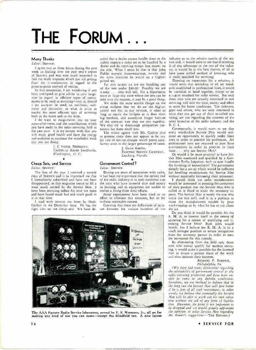
THE FORUM... Many Thanks Editor, SERVICE:
I spent two or three hours during the past week in looking over the past year's copies of SERVICE and was very much surprised to find the ready response which you are getting from the manufacturers in regard to the point-to-point method of testing.
In this connection, I am wondering if you have attempted to give advice in your maga- zine in regard to efficient types of instru- ments to be used in servicing-that is, should a set analyzer be used, an oscillator, volt- meter and ohmmeter, or what in order to render the most efficient type of servicing both in the home and in the shop.
I do want to congratulate you on your accomplishments and the contributions which you have made in the radio servicing field in the past year. It is my earnest wish that you will enjoy good health and have the energy and ambition to continue the wonderful work that you are doing.
J. E. SMITH, PRESIDENT, NATIONAL RADIO INSTITUTE, Washington, D. C.
Cheap Sets, and Service Editor, SERVICE:
The first of the year I received a sample copy of SERVICE and it so impressed me that I immediately subscribed and have not been disappointed, as this magazine seems to fill a want much needed by the Service Man. I have been servicing radios for over ten years and have found much bad and much good in it in that time.
I read with interest the letter by Herb. Corbett in the December issue. He has the right idea on the cheap sets. We have de-
cided that a dealer cannot handle them as the public expects a radio set to be handled by a dealer and do anything except lose money on the sale. What I mean by that is that John Public expects demonstrations, service and the same attention he would on a higher - priced set.
For this reason we are not handling any of the sets under $40.00. Possibly we are wrong . . time will tell. For a department store or large city store where the sets can be sold over the counter, it may be a good thing.
We make the same service charge on the cheap midgets that we do on the higher - priced sets for, in our opinion, it takes as long to repair the midgets as it does their big brothers, and sometimes longer because of the compact way they are put together. We also try to discourage prospective cus- tomers for these small sets.
The writer agrees with Mr. Corbett that at present there does not appear to be any set rate of service charges which prove satis- factory even in the larger percentage of cases.
J. GLEN KIRSTE, ELECTRIC SERVICE COMPANY, Leesburg, Florida.
Government Control? Editor, SERVICE:
During ten years of association with radio, it has been my experience that the service end of the radio industry is in such condition that the men who have invested time and money in learning and in equipment are unable to realize a living from their efforts.
Many experiments have been tried in an effort to alleviate this situation, but so far without noticeable success.
Granting that there are differences of opin- ion between the various branches of the
The AAA Factory Radio Service laboratory, owned by F. S. Wetmore, Jr., all set for making any kind of test you can name-except the blindfold test. A nice layout
74
industry as to the relative merits of the ser- vice end, it would seem to me that if servicing is of any advantage to the rest of the indus- try, it would be to the best interest of all to have some settled method of knowing who is really qualified for servicing.
Drawing on experience for a solution, it would seem that according to all set stand- ards established in professional lines, it would be unethical to band together, except to set a higher standard for radio service. But only those men who are actually interested in real servicing will take the time, money and effort to unite for better conditions. The tinkerers, gyps and others, who are only interested in what they can get out of their so-called ser- vicing, are not regarding the interests of the other branches of the radio industry and the B. C. L.
Consequently, it would seem to me that every worthwhile Service Man would wel- come an opportunity to qualify under State Jaws in order to practice his profession. All professional men are required to pass State examinations in order to practice in their State ... why not Service Men?
Or would it be more practical to have Ser- vice Men examined and qualified by a Gov- ernment Radio Inspector, such as now handle the licensing of transmitters? The government already has a set-up which would be sufficient for handling examinations for Service Men without materially increasing their personnel.
I should think the radio manufacturers would be interested in assuring the consumers of their product that the Service Man who is called in is fitted to make the necessary re- pairs. The Service Man is surely the one who keeps the sets sold, and is in a position to cause the manufacturers trouble by poor workmanship or by what he has to say about the set.
Do you think it would be possible for the R. M. A. to interest itself to the extent of agitating for a system of qualifying and li- censing Service Men? Both sides would benefit, but I believe the R. M. A. is in a much stronger position to secure recognition from the necessary parties in order to start the movement for this remedy.
By eliminating from the field only those men who cannot qualify for modern servic- ing, it would make it possible for the licensed men to secure a greater share of the work and thus increase their incomes.
RICHARD P. ROBERTS, Philadelphia, Pa.
(We have had many discussions regarding the advisability of government control of the radio servicing profession and have been un- able to come to any definite conclusion. Somehow, we are inclined to believe that in the long run the Service Man will fare better if he is free of all such restrictions; in other words, we believe that eventually the Service Man will be able to work out his own salva- tion without the aid of any form of legisla- tion. However, the point is too important to be dropped and we would greatly appreciate the opinions of other Service Men regarding Mr. Robert's suggestions.-THE EDITORS.
SERVICE FOR
www.americanradiohistory.com

THE BOOK of the YEAR PUBLIC ADDRESS SYSTEM DESIGN, INSTALLA- TION AND SERVICE is the book the modern, wide- awake Service Man requires to enter the Public Address field. I't has been especially prepared with the service field in mind and is written for the Service Man who wants to expand his activities by making small and mediummsized Public Address Installations.
In this book you will find the practical information which has been lacking for so many years-written in a manner which you can easily understand and apply to profitable practice.
PART I Part I covers the Kind of Systems required-Acoustic Power Determination-Distribution of Power into Loud Speakers and Headsets, and Calculation of the Amount of Power Needed-Pre-amplifiers and their Arrangement-Design and Selection of Power Ampli- fiers-Calculation of Gain Required-Design of Power Packs-Tubes for Power Amplifiers-Class A and Class B Amplifier Systems - Electric Pick-ups - Attenuator Pads, how to Make and Use them-Volume Level Indicators, Application and Design-Mixing Transformers and Arrangements-Coupling Trans- formers-Power Amplifiers in Parallel Combinations- Arranging Patching Panels, etc.
PART II Part II covers the normal servicing problems that arise in Public Address Work. This section is written in the usual Rider manner, explaining troubles and their remedies in complete detail. Practical installa- tions are also considered with wiring diagrams of various P -A. systems such as Samson, Radio Receptor, etc.
PART III Part III covers Acoustics and Acoustical Treatment, and was written specifically for this book by Vesper A. Schlenker, one of the foremost acoustical engineers in this country. Mr. Schlenker covers in easily under- standable language, the Fundamental Relations of Radiated Sound-Acoustical Properties of Rooms- Frequency Analysis of Noise-Determination of Acoustical Conditions and Noise Level, and the Amount of Power Necessary to Over -ride the Noise-Kinds of Noises present in various Installations and their Minimization-Breakdown of Noises into Frequency Bands-Acoustic Materials and their Properties- Specific Treatment of Rooms-Areas to be Treated- Installation of Acoustic Materials-Applications to Various Kinds of Surfaces in Old and New Buildings. Also chapters on Microphones and Pick-ups-General Types of Loud Speakers and Driving Units-Character- istics of Speakers, their Radiation Properties, and where they should be located. The Appendix to the volume contains a complete decibel table covering the full range of power values to be experienced in practice. This table eliminates the need for extensive calculation. You need this book. It is absolutely indispensable to any man who expects to do Public Address work. Order your copy today. Price, Post Paid, $3.50.
USE THIS COUPON - - - - - - - JOHN F. RIDER 125 West 40th Street New York City, N. Y.
Here is $3.50 for my copy of "Public Address System Design, Installation and Service."
NAME
ADDRESS
CITY STATE
FEBRUARY, 1933
Is Your Future Worth 30? Let me mail you my FREE BOOK-
Mr. B. H. Rietake, Pres.
"PRACTICAL RADIO ENGINEERING"
Write for this interesting booklet. If you have the necessary ambition and experience, this Advance home -study course will help give you the knowl- edge necessary for specialization in the more advanced fields of radio and
Capitol Radio Eng. Inst. its many branches.
. . . SOON! THE MOST
IMPORTANT ANNOUNCE-
MENT WE HAVE
EVER MADE
... watch for it!
Here It Is Write
for this Book Now! It Proves Training
Is Neces- sary for Advance.
ment.
PRACTICAL
RADIO
ENGINEERING
MAIL THIS TODAY!
Capitol Radio Engineering Institute Dept. S-2
14th and Park Road, N. W., Washington, D. C. Please send me your Free, 28 -page booklet, "Practical Radio
Engineering," at no obligation to me.
Name
Address City N. Y. City Representative-M. Schaft. 200 Broadway-Phone Rector 2.4152
oqja. a/4rl«X
MIMI IS
-FREE- THE LATEST
ALLIED BOOK PREPARED EX- CLUSIVELY FOR
THE RADIO SERVICEMAN
Write for our new 1933 World's Fair Issue of the ALLIED radio catalog - an astounding guide to radio's finest mer- chandise, lowest prices, and quickest service. It is pre- pared exclusively for you as a Radio Serviceman- that you may profit. Send for this new ALLIED cata- log today. It is absolutely
FREE FREE and worth having.
SAY You SAW IT IN SERVICE
OVER 2 MILLION
RADIO SETS Statistics show that during the next few
months, over 2 million radio sets sold in 1929, 1930, and 1931 will re- quire servicing and replacement parta. You will get a good share of that business and your reputation will be built up largely on the parts you use.
Let ALLIED supply you with exact duplicate replacements
for power transformers, volume controls, condensers, resistors, tubes, speakers, modernizing equipment, etc. You can depend on ALLIED for-
MERCHANDISE that is new and clean- COMPLETENESS-Radio's largest stock-. VALUES that bring you profits and savings- SPEED-24 hour rush service- PERSONALIZED SERVICE- RELIABILITY - the ALLIED name means permanence and stability.
Alli¢d\r'Radío CORPORATION
833 W. JACKSON BLVD. CHICAGO, ILL.
75
www.americanradiohistory.com

THE MANUFACTURERS... I. R. C. Resistor Indicator
The Resistor Indicator recently announced by the International Resistance Co. is a wire - wound job and therefore can be applied to most any circuit structure, including those of amplifiers, as the unit can handle heavy current.
The Resistor Indicator is a clever arrange- ment. There are two leads with clips and these are connected across the open resistor in receiver or amplifier. The "feeler" or
prod, as shown in the accompanying illustra- tion, is then run along the exposed portion of the wire, directly under the calibrated resistance markings, and brought to a stop when the operation of the receiver or ampli- fier is again normal-or when the correct voltage reading for that particular portion of the circuit is reached. This point at which the prod makes contact on the wire then represents the resistance value of the open resistor-the value being read from the scale, such as 40M, or 40,000 ohms, as in the illustration.
The I. R. C. Resistor Indicator is also very handy as a temporary voltage divider for tapping off fixed voltages from a supply. Resistance values slightly in excess of 100,000 ohms can be covered. By adding resistors of known value in series, the range can be extended to most any figure desired.
New "Universal" Units Universal Microphone Co. has announced
a group of new units particularly adaptable to public-address work. There is, for in- stance, a new remote control panel of Uni- versal make, which is a one -stage microphone amplifier, which may be used in connection with mikes or electric pickups, and as a tele- phone amplifier, a pre -amplifier for home recording, a phono -mike mixing panel, etc.
The panel consists of a single stage ampli- fier to bring the output level of the micro- phone up to approximately that of the phonograph pickup. Equipment is portable, housed in black enamel casing, and includes "A" and "B" with total weight of 20 pounds. There are two output combinations-a low and high impedance-one designed to feed into an amplifier, and the other to feed into a line of the order of 400 to 600 ohms.
The unit is equipped with volume controls and tone control, and uses a type 230 tube.
Universal also has some other input stages, one designed for two -button microphones and the other designed for single -button micro- phones.
Philco Interference Eliminators Philco has announced a new line of con-
denser units especially suitable for interfer- ence elimination work.
Two of these condensers are of the tubular type of construction with self-supporting leads. They are small in size so that they can be used in a limited space, such as within the casing of a small motor, etc., and come in capacities of .05 mfd. and .1 mfd.
In addition to the small condenser units listed above, Philco has available four addi- tional larger capacity condensers for heavier interference elimination. These are uncased condensers, available in 0.25 mfd., 0.5 mfd., 1.0 mfd., and 2.0 mfd.
Balanced Antenna System
The Clough-Brengle Company, of 1134 W. Austin Avenue, Chicago, have announced their new Staticlear Balanced Antenna Sys- tem, specifically designed to eliminate man- made interference.
The Staticlear system departs from the usual type of system in that it employs a two - wire transmission line, without a shield cov-
ering, the two wires of the line being continuously transposed from the point of the antenna to the point of the receiver. The use of this arrangement eliminates capacity to ground which is sometimes excessive when a singe or double shielded cable is used, with the shield grounded.
The complete outfit consists of 75 feet of two -wire transposed line, an antenna trans- former and a receiver transformer. The antenna transformer is used to match the impedance of the antenna to that of the line, and the receiver transformer to match the input impedance of the receiver to that of the line. The line itself is balanced to ground.
It is stated that the system is so designed that it may also be used in connection with an antenna for short-wave reception with no appreciable losses and a decided gain in sig- nal over noise.
Na-Ald Universal Tube -Checking Adapter
The new Na-Ald Universal Tube -Checking Adapter, Type 950XYL, illustrated herewith, permits the checking in most any make of tube checker of forty-seven different tubes. All these forty-seven tubes are checked in this adapter when used in the UY screen -grid
socket of a tube checker having a filament voltage switch; with tube checkers having 14, 25 and 30 -volt filament potentials the 14, 17, 43 and 48 tubes can also be checked with this adapter in addition to the forty-seven tubes.
The adapter has the proper resistance net- work to protect diodes from excessive current as well as to safeguard the tube checker meters from the high current of the mercury- vapor rectifiers.
The Universal Tube -Checking Adapter is sold complete and ready for operation, or in kit form with diagram and instructions for assembling and wiring.
Wirt Rotary Snap Switch The Wirt Company have brought out a
new rotary snap switch with a rating of 3
amperes at 125 volts. It is of the single
pole, single throw type and has low contact resistance. It is designed primarily for use as a power switch for radio receivers and is of the single -hole mounting type.
Littelfuse Protection Plan Littelfuse Laboratories have made the an-
nouncement that hereafter all instruments protected by Instrument Littelfuses will be covered by a $100 Indemnity Protection Guarantee.
According to the manufacturer, this policy has been made possible by several improve- ments in their line during the past year, in- cluding the use of platinum wire in the finest capacities which, it is said, is much more reliable than the metallized quartz fibre for- mally used. A special type of mounting (see illustration) is used for this wire, the support wires being united by a glass bead.
76 SERVICE FOR
www.americanradiohistory.com

BINDERS FOR
SERVICE Every issue of SERVICE contains many articles which are not only val- uable today but will be worth many dollars to you at some future date. Preserve your copies of SERVICE in this hand- some, practical binder. You'll never regret this purchase.
HOLDS 24 COPIES -2 YEARS' ISSUES This handsome, two-tone blue, imitation leather binder is of De Luxe library construction, stamped in gold. It is the most secure method of holding your copies of SERVICE. The individual issues, once bound, cannot fall out or be pulled out and yet it takes less than half a minute to insert or remove the contents.
You know the value of having this information at your finger-tips. The magazines are kept clean and ready for instant reference. With the index and this binder you have the year's most important service information filed and in perfect condition. This SERVICE binder will protect your copies permanently.
Price $2.00 Postpaid
JOHN F. RIDER PUBLICATIONS, INC. 1440 Broadway New York, N. Y.
J4r Vrrakrrn Atlantir (nitu Nrui JrrIIru
On t4g Imarbnialk
Under New Management
FEATURES NEW LOW RATES FOR BOARDWALK HOTEL
ACCOMMODATIONS
PER PER DAY !9 el PERSON With Meals and Private Bath Hot and Cold Sea Water Unexcelled French Cuisine Complete Garage Facilities
Concert Orchestra
EMANUEL E. KATZ, Managing Director
Radio Servicemen: Here's PROFIT and Proteetion for 1"OF
You should receive a profit from two sources on every service job you do. First, by charging a legitimate price for your labor, and second the profit you secure by purchasing your materials at a trade discount. Both profits are necessary to your success.
The RADOLEK Company assists you in in- creasing both. By placing at your disposal an immense stock of over 7,000 different Radio items we make it possible for you to select and secure PROMPT DELIVERY on practically any component needed for the repair of any stand- ard make or model Radio receiver. The TIME SAVED through elimination of misfit mer- chandise and shipping delays makes your working day more productive and swells your earnings.
By quoting YOU the LOWEST WHOLESALE PRICES on BRAND NEW MERCHANDISE direct from the factories of America's leading Radio Manufacturers. We refuse our catalog to any except those whose connection with the Radio industry entitles them to receive whole- sale prices, we SAVE YOU MONEY AND PRO- TECT YOUR PROFITS by maintaining the confidential nature of the prices YOU pay.
YOU need this protection-every man who depends upon Radio service work for a living needs it. Why not encourage it by supporting those who are pioneering it? If you haven't a copy of the 1933 Radolek Profit Guide fill out and attach the coupon below to your letter- head, business card or furnish other evidence of your status in the Radio field, and mail it today!
The RADOLEK CO. 702 Canal Station Chicago, III.
COUPON Enclose with this Coupon a copy of Your Letterhead or Business Card and
MAIL TO THE RADOLEK CO. 702 CANAL STATION CHICAGO, ILL
Name
Address
City ----------State - -- - - -- - J FEBRUARY, 1 9 3 3 SAY You SAW Ir IN SERVICE 77
www.americanradiohistory.com
Index oF Monthly Literature BROADCAST
Amplifiers, A -F.
Acoustically Compensated Volume Con- trol Wolff and Cornell, Electronics, pp 50, February, 1933
Volume Controls in Audio Channels P. V. O'Rourke, Radio World, pp 4, February 18, 1933
Amplifiers, R -F.
Band -Pass Filter (Construction) Radio Review & Television News, pp 268, February, 1933
Gaseous "Noise Gate" Tube J. F. Dreyer, Electronics, pp 40, February, 1933
General
Circuits of "Universal" Midget Sets Radio Retailing, pp 35, February, 1933
Matching Impedance Loads Radio Review & Television News, pp 264, February, 1933
Receivers
Hammarlund Comet "Pro" (New Model) L. W. Martin, Short Wave Craft, pp 604, February, 1933
Midwest All -Wave Super, Part I
Taylor and Dorf, Radio News, pp 544, March, 1933
Scott All -Wave Super (New Model) Taylor and Borst, Radio News, pp 542, March, 1933
PUBLIC-ADDRESS
Acoustically Compensated Volume Con- trol Wolff and Cornell, Electronics, pp 50, February, 1933
Class AAA P -A. Amplifier (Construc- tion) L. J. Littmann, Radio -Craft, pp 536, March, 1933
Handling P -A. Rentals Radio Retailing, pp 24, February, 1933
Rack and Panel P -A. System, Part II (Construction) W. C. Dorf, Radio News, pp 536, March, 1933
Sound Absorption and Materials G. W. Baker, Projection Engineering, pp 11, January, 1933
Technical Terms for the Projectionist Projection Engineering, pp 21, January, 1933
Velocity Microphones (Construction) C. W. Melotte, G. A. Elliot, QST, pp 23-24, February, 1933
SHORT WAVE
A -C. Super -Wasp Brought Up to Date A. A. Dolid, Short Wave Craft, pp 590, February, 1933
Hammarlund Comet "Pro" (New Model) L. W. Martin Short Wave Craft, pp 604, February, 1933
Midwest All -Wave Super, Part I
Taylor and Dorf, Radio News, pp 544, March, 1933
National AGS Short Wave Super James Millen, Radio News, pp 546 March, 1933 (Also Modern Radio, pp 7, February, 1933)
Scott All -Wave Super (New Model) Taylor and Borst, Radio News, pp 542, March, 1933
Short Wave Antenna Design and Con- struction Don C. Wallace, Radio, pp 14, January, 1933
TESTING SYSTEMS
A Perpetual Analyzer L. W. Hatry, Modern Radio, pp 10, February, 1933
Improving the D -C. Set Tester B. J. Montyn, Radio News, pp 538, March, 1933
Low and High Resistance Ohmmeters (Design) A. H. Lynch, Radio -Craft, pp 535, March, 1933
Oscillator Circuits J. E. Anderson, Radio World, pp 3.
January 28, 1933
Practical Tests for Microvoltmeters M. Ferris, Modern Radio, pp 13, February, 1933
Resistors for Test Meters Radio News, pp 554, March, 1933
Shallcross 651 Set Tester (Construction) P. Shallcross, Radio -Craft, pp 534, March, 1933
Simple Capacity Bridge M. O. Sharpe, Radio News, pp 552, March, 1933
V. T. Voltmeters for Servicing C. H. W. Nason, Radio -Craft, pp 544, March, 1933
TUBES
Filamentless Tube (Cold Cathode) Radio -Craft, pp 528, March, 1933
Gaseous Discharge Tubes for Radio Receiver Use J. F. Dreyer, Electronics, pp 40, February, 1933
New Detectors, Rectifiers and Amplifiers Electronics, pp 35, February, 1933
New -Tube Base Connection Table Radio Retailing, pp 43, February, 1933
Tube Reference Index Radio -Craft, pp 532, March, 1933
MISCELLANEOUS
Electronic Musical Instrument (Con- struction) C. E. Denton, Radio -Craft, pp 522, March, 1933
Improving Home Recording on R.C.A., G.E. and Westinghouse Sets
H. F. Pitzer, Radio -Craft, pp 539, March, 1933
Wavelength -Kilocycle Conversion Table Radio World, pp io, February 18, 1933
All articles listed on this page are cross-indexed for your convenience. Titles given are not necessarily the titles of the original articles, but in each case serve to determine the substance of the article. Listings marked with an asterisk (*) are abstracted in this issue. The material in each issue of SERVICE is alphabetically indexed on the Contents Page.
78 SERVICE
www.americanradiohistory.com

' I ,11,,,C
We We Repeat Our Most Popular Offer
SERVICE SAN. SAYS
I'VE been in the service gaine lung enough to know a good thing when I see it, and this method of testing a radio
-et or amplifier by means of point-to-point resistance measurement is sure the berries.
I should say that two years ago this method would not have stacked up so well with good, old voltage analysis-hut with these new-fangled circuits with automatic volume control, duo -diodes and "hush -ent up" tuning, there are more resistors than you can shake a soldering iron at.
Some of these trick circuits are so con- stituted that it is next to impossible to make any sort of a voltage analysis that will indicate the conditions in all portions of the circuit. Therefore, it is essential to resort to the ohmmeter to get results.
More and more of the fellows are turn- ing to the ohmmeter for carrying out all tests, and I know that some of the gang around here have gotten so proficient that they can shoot a resistance test on a re- ceiver as rapidly as they formerly carried out a voltage test.
Now, if you want your resistance tests to he worth a hang, you've got to have a good ohmmeter-which means that it must be accurate not only for high values of resistance, but also the low values.
Accuracy in an ohmmeter is dependent on two factors: i.e., the accuracy of the meter used-and most good meters are accurate nowadays-and the accuracy of the resistors used in the ohmmeter to ob- tain various readings. If the resistors are not accurate to begin with, or fail to main- tain their accuracy over a long period of lime . well, you might ,just as well test with a battery and flashlight bulb!
So many of the fellows are building their own ohmmeters that I wanted to stress Ihi- accuracy point. Accuracy is not mil\ a matter of hitting the right value right on the nose, but also is a matter of the con- struction of the resistor that it may huh/ this accuracy.
To obtain and maintain accuracy -
friends at IRC go in for wire -wound re- sistors which are directly calibrated agaiii-i standards. These resistors are made a-pe- cially for ohmmeters and other neasuri i
instruments which must be accurate.
(Indicator may be bought separately for $2.40)
Once more-the biggest, most popular offer IRC has ever made! For less than the regular cost of the Resistors alone, you get: (1) The famous IRC Re- sistor Indicator, value $2A0: (2) Sturdy steel cabinet, value $2.50; (3) Resistor Repin,e- ment Guide, value $1, and I I )
Color Code Chart, value 25e-- -
$23.55 worth of service helps for only $16.50. Cabinet contains 69 IRC Resistors of most needed types which ordinarily sell for $17.40 alone.
The IRC Resistor Indicator is an indispensable service tool. No circuit information or ohm- meter necessary. Indicator in- stantly gives replacement value of damaged unit and is valuable for checking other Resistors as well.
Offer good for limited time only. Don't miss it! Send check or M.O. at once.
(Price higher in Canada).
This Resistor Indicator FREE
with This IRC Resistor
Kit!
OCK CARD
(Tools not included)
IRC MOTOR RADIO SUPPRESSORS (7ryta74
MOTOR MOW e SUPPPESSOR
SPART: l'ii (; TYPE
mamma
DISTRIBUTOR TYPE
C ORLE rlPti Helpful Booklet, "The Suppression of Motor
Noises," free with each Suppressor Kit.
1933 will be a big year for auto radio more new sets sold-more replacements. Cash in on oppor- tunil by using IRC Suppressors on every job.
SUPPRESSOR KITS M-4 Kit (four -cylinder cars), Four
Spark Plug Resistors, one Distributor Type Resistor $1.50
M-6 Kit (six -cylinder cars), Six Spark Plug Resistors, one Distributor Type Resistor $2.10
M -N Kit (eight -cylinder cars), Eight Spark Plug Resistors, une Distributor Type Resistor $2.70
Individual Suppressors, all types 30c each.
INTERNATIONAL RESISTANCE CO. 76 Wellington St., W. Toronto, Ont., Canada
2006 Chestnut Street Philadelphia, Pa.
SAY You SAW IT Irl SERVICE
www.americanradiohistory.com

RIDER'S PERPETUAL TROUBLE SHOOTER'S MANUALS ARE THE STANDARD OF THE RADIO INDUSTRY
- THE DIAGRAM YOU REQUEST IS
No LONGER AVAILABLE FROM OUR FILES. WE SUGGEST -THAT YOU BUY RIDERS PERPETUAL TROUBLE. SHOOTERS
MANUAL WHICH CONTAINS THE SERVICE INFORMATION COVERING OUR ENTIRE LINE.
4
3J1 FI3Z FI3/AM ar` AVI
-WE ARE PLEASED TO OFFER ADVICE TO OUR FORMER STUDENTS. THE BEST
MANUAL COVERING RADIO RECEIVERS 15 JOHN F. RIDERS PERPETUAL TROUBLE
-SHOOTER'S MANUAI
7 -ENCLOSED HEREWITH IS OUR DATA BOON. IF YOU WANT MORE COMPLETE SERVICE INFORMATION BUY RIDERS PERPETUAL TROUBLE SHOOTER'S
RECEIVER MANUFACTURERS SCHOOLS INSTRUMENT MANUFACTURERS ALL RECOMMEND RIDER'S TROUBLE SHOOTER'S MANUALS
Rider's Volume II contains wiring diagrams and service data on old as well as new receivers. Some of the information on old sets was not available when Volume I was published. Therefore, unless you have Rider's Volume II, you are missing necessary information on sets which need service to- day-sets produced in 1927
1928
SERVICE DATA ON THESE AND MANY OTHER SETS WILL BE FOUND IN VOLUME II.
Advance Electric Atwater Kent American Bosch Bremer Tully Brunswick Bulova Cable -Nelson Capehart Colonial Columbia Crosley Echophone Erla Fada General Electric General Motors Grigsby Grunow Howard Radio Kennedy Montgomery Ward Ozarka Philco Sears Roebuck Silver -Marshall Sparks Withington Steinite Stewart Warner Stromberg Carlson Sentinel U. S. Radio & Television Ware Mfg. Co. Wextark Radio Zenith
1929 1930
1931
Volumes I and II are entirely different-there are no duplicating pages. More and more of the receivers shown in Volume II are coming into your shop for service. You can use this information immediately-the money you spend for Volume II will be returned many times through the service jobs which you can handle with this data. Volume II contains many pages of wiring diagrams and service data on old as well as new sets, power packs, eliminators, auto -radio sets, chassis lay- outs, voltage data, electrical values, color coding, alignment data, trimmer locations, socket layouts, peak frequencies, etc. SPECIAL ... More than 50 pages of point-to-point resistance data. List price $5.00 post paid.
If there is no dealer near you, clip the coupon now and buy direct from us.
RADIO TREATISE COMPANY, INC. 1440 BROADWAY NEW YORK, N. Y.
RADIO TREATISE COMPANY, INC., 1440 Broadway, New York, N. Y.
I want a copy of RIDER'S TROUBLE SHOOTER'S MANUAL, VOLUME II. Here is my $5.00 which will bring it to me post paid.
NAME
ADDRESS
CITY STATE
PRINTED BY
BLANCHARD PRESS NEW YORK
www.americanradiohistory.com