A microprocessor-based Load voltage control using an AC ...
19
A microprocessor-based Load voltage control using an AC chopper A.S. ZEIN EL DIN, Z.MOHAMED, A.A.EL-HEFNAWY, and A.S.ABDEL-GHAFAR Beparment of Electrical Engineering, Faculty of Engineering, Menoufia University, Shebin El-kom, Egypt. Tel.: XX(048) 221549, Fax.: XX(048) 235695, e-mail : IN % "et001@ shebin.eun.eg" Abstract Pulse width Modulated (PWM) control technique for an a-c choppers using harmonic elimination method is proposed. The firing switching instants of a-c chopper for the proposed technique is derived theoretically. By using a microprocessor as a controller, makes it possible to store the firing switching instants time as a look-up table for different load voltage values. Two MOSFET's are used as an a-c chopper. Experimental results verifying the simulation analysis of the a-c chopper fed static (R-L) load and dynamic load (1-ph. induction motor). The proposed strategy is low cost, simplified, and control effective. Keywords A-C chopper, MOSFET's, microprocessor, PWM 1. Introduction A-C choppers or ac voltage regulators have been widely used to obtain variable a-c voltage from a fixed a-c source [I]. A-C choppers are widely used in applications such as industrial heating, lighting control, soft starting of induction motors, speed controllers fans and Manuscript received from Dr: A. S. Zein El- Din at: 111121 1997, accepted at: 261 211998, Engineering research bulletin, Vol. 21, No. 2, 1998, Menoufiya University, Faculty of Engineering, Shebin El- Kom, Egypt, ISSN. 1110-1180.
Transcript of A microprocessor-based Load voltage control using an AC ...

A microprocessor-based Load voltage control using an AC chopper
A.S. ZEIN EL DIN, Z.MOHAMED, A.A.EL-HEFNAWY, and A.S.ABDEL-GHAFAR
Beparment of Electrical Engineering, Faculty of Engineering, Menoufia University, Shebin El-kom, Egypt.
Tel.: XX(048) 221549, Fax.: XX(048) 235695, e-mail : IN % "et001@ shebin.eun.eg"
Abstract
Pulse width Modulated (PWM) control technique for an a-c choppers using harmonic
elimination method is proposed. The firing switching instants of a-c chopper for the
proposed technique is derived theoretically. By using a microprocessor as a controller,
makes it possible to store the firing switching instants time as a look-up table for different
load voltage values. Two MOSFET's are used as an a-c chopper. Experimental results
verifying the simulation analysis of the a-c chopper fed static (R-L) load and dynamic load
(1-ph. induction motor). The proposed strategy is low cost, simplified, and control
effective.
Keywords
A-C chopper, MOSFET's, microprocessor, PWM
1. Introduction
A-C choppers or ac voltage regulators have been widely used to obtain variable a-c voltage
from a fixed a-c source [I]. A-C choppers are widely used in applications such as industrial
heating, lighting control, soft starting of induction motors, speed controllers fans and
Manuscript received from Dr: A. S. Zein El- Din at: 111121 1997, accepted at: 261 211998, Engineering research bulletin, Vol. 21, No. 2, 1998, Menoufiya University, Faculty of Engineering, Shebin El- Kom, Egypt, ISSN. 1110-1180.

pumps. Many of these are conventional phase-controlled a-c controllers using thyristors,
which have the advantages of simplicity of the control circuit and large power capability.
However, these have the inherent drawbacks that power factor decreases when the firing
angle increases and that, Since the content of the line current harmonics is relatively large.
The size of the passive filter circuit becomes bulky. These drawbacks can be overcome by
using PWM a-c chopper.
This chopper offers several advantages such as sinusoidal input current with unity power
factor, fast dynamics, and significant reduction in filter size. Some of PWM a-c chopper
that has been used is symmetrical angle control, asymmetrical angle control and high-
frequency time ratio control [2]. The developments achieved in the field of power
electronics made it possible to improve the performance of electrical system utilities.
Usually solid state power switching devices are employed in source conditioning by
changing either its magnitude or hequency such as converter, inverters, choppers, regulators
or cycloconverters. An a-c voltage regulator is used as one of the power electronics systems
to control an output ac voltage for power ranges horn few watts up to fractions of mega-
watts. Phase-angle microprocessor based hatmonic elirnination in chopper type ac voltage
regulators is used [3]. In this type of regulator, output voltage is controlled by varying the
ON/OFF time ratios of a series controlled switch using a microprocessor as a controller
makes it possible to vary firing instants according to a predetermining firing instants such
that selected dominant lower order harmonics can be eliminated. This in turn leads to
improve system power factor and efficiency.
In this paper, a PWM ac inverter harmonic elimination technique is used. For a half cycle
of the a-c source, a PWM switching fimction composed of M pulses is assumed. Fourier
coefficients of PWM output voltage are then obtained, which are expressed in terms of the
M switching point variables. In addition, the constrains for required output fundamental
voltage and elirnination of harmonics up to 2M-1 order, yield M equations. Solution of
these equations enables the derivation of the required PWM switching paftern for the
chopper [4]. Only two MOSFET's controlled by a microprocessor are used to achieve
PWM technique for an a-c chopper. Different loads are used R-L load and dynamic load
(1-ph. induction motor) in this system. Practical verification of the theoretical predictions is
presented.
2. Description of PWM a-c chopper
The power circuit of a PWM a-c chopper is composed of two uncontrolled bridges and
pair of MOSFET's,, connected one in series, and one in parallel (freewheeling) with the

load as shown in Fig. 1. The series connected MOSFET regulates the power delivered to
the load, and the parallel one provides the freewheeling path to discharge the stored energy
when the series one is turn off . A power MOSFET is a voltage-controlled device and
requires only a small input current. The switching speed is very high and the switching
times are of the order of nanoseconds. Synchronization signal is transferred into carrier
signal through synchoization circuit and input to microprocessor. An INTEL 8085
microprocessor is used in this applications because it is available, low cost and sufficient.
An assembly program stored in EPROM memory interfaced with microprocessor selects
the required switching instants f ian a look-up table that contains different switching
instants corresponding to K value. Charging a timer for ON-time or OFF time and output
two signals from output port of microprocessor delivers Two MOSFETs. A ~~nchonization
circuit and driver circuit of MOSFET are shown in Figs. 2,3 respectively.
Fig. 1 A proposed system of a PWM a-c chopper
- - - Fig. 2 Synchronization circuit

330 ohm I + 5 volt +I 5 volt 5
7400 3
1 K ohm 1 I
MOSFET ; I - - - - - - - - PULSES-:
- - -
Fig. 3 Driver circuit for MOSFET
Consider the output voltage waveform shown in Fig. 4, with six offperiods embracing
five voltages pulses per half cycle. Here, number of On and OFF periods per half cycle is
eleven that is the dominant harmonic for PWM firing strategy. Assuming arbitrary
switching angles > ** 6-. a?3 .. a4' aS per quarter of a cycle, wave is symmetric
around nl2 and performing frequency harmonic analysis yields
2 A(n) = -
71;
&n(n-I)@ - sh(n + I)@ n12 lo p.u.
n - l n + l B( I ), B(3), B(5) . . . . . . . . . B(m) = o (quarter-wave symmetry)
It is clear that there exist five unknown which in turn requires
five equations for its evaluation. This implies that there are five constraints ought to be
fidfilled in selecting values of these angles. These constraints can be set in the following
way:

Where: K = ratio between peak value of fundamental load voltage component to peak value
of input supply voltage. It could be then concluded that number of constraints equals
number of switchings per quarter of a supply voltage cycle. This means that increasing
number of switchings will in turn lead to eliminate more harmonics. [3].
Fig. 4 Voltage waveform harmonic elimination
3- Simulation and Experimental results
A program was constructed for evaluating MOSFET switching angles with eleventh
components eliminated. A flowchart is shown in Fig. 5 represents a program. Load
current is calculated fiom the following equation:
VL = VS at main MOSliET is turned ON but VL= 0 at main MOSFET
is turned OFF
So, the last equation is solved using 4 th order Rung-Kutta technique taking a step of
calculation is 0.1 m. Sec., hence supply current is determined from load current .
Theoretically, and in ideal case, supply current = load current in case of turning ON main
MOSFET, but reaches to zero otherwise.

The calculated and experimental results are presented for five switching instants per quarter
cycle of supply voltage waveform and R-L load with R= 56 ohm and L= 50 m.H., supply
voltage = 11 0 volt and supply ftequency = 50 Hz. In ideal case, during turn on of main
MOSFET (in series) , load voltage equals to supply voltage (neglect drop voltage through
uncontrolled bridge and MOSFET) but in other hand, at main MOSFET is turn off, load
voltage equals to zero because of freewheeling MOSFET parallel path across load. The
main, parallel MOSFETs and synchronization signal at different values of factor K where
K = ratio between peak value of fundamental load voltage to peak value of input supply
voltage is shown in Fig. 6, the result shows ,that a good accuracy of a zero crossing
determined by a microprocessor program and hence an appropriate pulse to MOSFETS.
Also, simulation studies of supply current, load current and terminal load voltage are
represented at Figs. 7a,b - 10 a, b for different values of K. A good agreement
between experimental and simulation results, load current is nearly sinusoidal as increased
in factor K. Instead of R-L load, a single phase induction motor (116 HP, 220 volt, 0.5
Amp.) is connected as a load. Supply current, motor current and terminal voltage for
different values of K are shown in Figs. 1 1 - 14 . The a-c input current has discontinuities
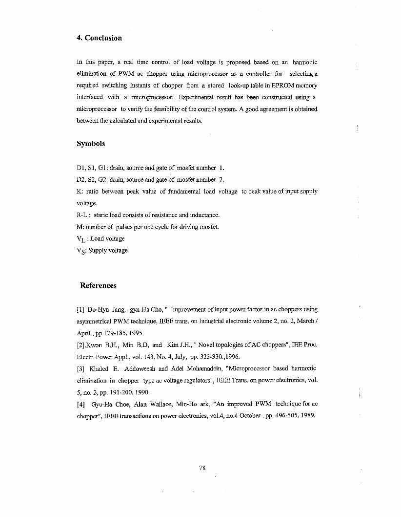
during every cycle even the load current becomes roughly sinusoidal. The speed of the
motor against the variation of factor K is shown in Fig. 15 . To make the filtering burden
less, it is required to increase the number of pulses per quarter cycle. Also this can improve
the wavform of the load voltage close to the pure sine wave but it is necessary to use a
suitable microcontroller or a fast microprocessor to generate a required pulse to MOSFETs.
Fourier analysis of load voltage for different values of K factor is shown in Fig.
16a,b,c,d

Start
\ Read K, input voltage, load parameters, maximum time and
\ step of calculations I
Call subroutine for determining required
switching angles
Using 4th order Rung-Kutta technique to calculate load
current
I Determine supply current
\ print supply current, load current and terminal voltage
increase time by step of calculation
d t i m e c= max imum1 ------. time
Fig. 5 A flowchart represents a simulation program.
4. Conclusion
In this paper, a real time control of load voltage is proposed based on an harmonic
elimination of PWM ac chopper using microprocessor as a controller for selecting a
required switchjng instants of chopper fiom a stored look-up table in EPROM memory
interfaced with a microprocessor. Experimental result has been constructed using a
microprocessor to verify the feasibility of the control system. A good agreement is obtained
between the calculated and experimental results.
Symbols
D 1, S 1, G1: drain, source and gate of mosfet number 1.
D2, S2, G2: drain, source and gate of mosfet number 2.
K: ratio between peak value of fbndamental load voltage to beak value of input supply
voltage.
R-L : staric load consists of resistance and inductance.
M: number of pulses per one cycle for driving mosfet.
VL : Load voltage
VS: Supply voltage
References
[I] Do-Hyn Jang, gyn-Ha Cho, " Improvement of input power factor in ac choppers using
asymmetrical PWM technique, IEEE trans. on Industrial electronic volume 2, no. 2, March /
April., pp 179-1 85, 1995
[2].Kwon B.H., Min B.D, and Kim J.H., " Novel topologies of AC choppers", JEE Proc.
Electr. Power Appl., vol. 143, No. 4, July, pp. 323-330.,1996.
[3] Khaled E. Addoweesh and Adel Mohamadein, "Microprocessor based harmonic
elimination in chopper type ac voltage regulators", lEEE Trans, on power electronics, vol.
5, no. 2, pp. 191-200, 1990.
[4] Gyu-Ha Choe, Alan Wallace, Min-Ho ark, "An improved PWM technique for ac
chopper", E E E transactions on power electronics, vo1.4, no.4 October , pp. 496-505, 1989.

. . . . . . . . . ; . . . . . . . . . j . . . . ............... . . . . . . . . . . . . . . . . . . . . . . . . . . . . . . . . . . . . . . . . . . . . . . . . . . . . . . . . .. E
FrwqC3>=50.00 H k PeriodC33=2O.OOms Duty cyC3>=51.1%
......... / . . . . . . . . . I . . . . . . . . . , . . . . . . . . . . . . . . . . . . . . . . . . . . . . . . . . . . . . . . . . . . .
......... . . . . . . . . . . . . . . . . . . . . . . . . . . . . .
FreqC33=50.00 Hz PeriodC33=20.00ms OutycyC3>=Sl.l%
(4 Fig. 6 Main MOSFET pulses, parallel MOSFET pulses and synchronization signal at
(a) K= 0.2 (b) K= 0.4 (c) K= 0.6 (d) K= 0.8

Main MOSFET pulses, and supply current (1 amp. = 1 div. / 16)
Main MOSFET pulses , Load voltage 1 S.@V 2 S0,OV r0.005 5.OOv f3 STUP
Main MOSFET pulses, and load current (1 amp. = 1 div. 156)
Fig. 7a Experimental results of R-L load for K=0.2
t ime (sec.)
Fig. 7b Simulation results of R-L load for K= 0.2

Main MOSFET pulses, and supply current
Main MOSFET pulses , Load voltage
. ! . , . . , . , , .
. . . . . .
. . , .
. . . . I . . . . : : : : i : ; : :
Main MOSFET pulses, and load current (1 amp. = 1 div. / 56)
Fig. l a Experimental results of R-L load for K=0.4
time (sec.)
Fig. 8b Simulation results of R-L load for K= 0.4

I . . : " ' , . . , . ,
Vrms(2)=19.43 V Vp-p(2)=214,1 V Vaug(2)=-742,ZmV Main MOSFET pulses, and supply current
(1 amp. = I div. 1 16)
Main MOSFET pulses , Load voltage
Main MOSFET pulses, and load current (1 amp. = I div. 156)
Fig. 9a Experimental results of R-L load for K=0.6
, I
, . . , , , , , : ,
o d d ' 0.64 t ime (sec. )
Fig. 9 b Simulation results of R-L load for K= 0.6

Main MOSFET and supply c&&t (1 amp. = 1 div. / 16)
5.WV 2 5 0 , O V +-0,OOs 5,0Om4 Snglf2ST1 . . . . . . , . . , . . ? . . . , , . I . . I . . . . , . . ( 7 . . . . , . . . t . . . . . . 7 . . .
b Main MOSFET puls& , Load voltage
Main MOSFET pulses, and load current (1 amp. = 1 div. 1 56)
Fig. 10a Experimental results of R-L load for K=0.8
Fig. lob Simulation results of R-L load for K= 0.8

Main MOSFET pulses and load voltage
......... i ...,...., i ........,; .,.,..... ; .,,...,. .L ....,,,. i ,..,...,. i ..,....., ,..,,.... ; ....,.,.. f A A
Main MOSFET pulses and supply current (Is = div. / 20 ohm) Fig. 1 1 Motor performance for K=0.2 and motor speed =287 r.p.m.

Main MOSFET pulses and load voltage 5 . o o V 2 lOOB TO. 00s 5.002/ Snslfi! STOI
-
i
i. .................. i.. ..... ..; ..... ....,....+ ........ i ......... i . . . . . . . . . i ....... . , i . . .......
+. - 1 . . . . . . . . '.... ..... i . ........ i . .. " " " ~ .. . . . . . . ........i......... i . ........ I ......... I . . . . . . . . .
- - A
Main MOSFET pulses and load current (IL = div / 0.1 ohm)
8 .
f ] ; 1; I f
......... .................... +.
. . . . . . . . . . . . . . . . . . . . . . . . . . . . . . . . . . . . . . . . . . . ..... A . ........................... I . . . . . . . . . ! . . . . . . . .* 4 $ %
Main MOSFET pulses and supply current (Is = div. 1 20 ohm) Fig. 12 Motor performance for K=0.4 and motor speed =2560 r.p.m.

Main MOSFET pulses and load voltage . 5 .OOV 2 50 .OF SO. 00s 5.002/ snslf2 STO T . ,
- . .................................................................................................. + -
"" .. " ' . . ... ................................................................................. - - A ................................................................................................. - i - A
Main MOSFET pulses and load current (IL = div / 0.1 ohm) 5 . 0 0 ~ 2 5 0 . 0 ~ SO. 00s s.oog/ Snslf2 ST0
Main MOSFET pulses and supply current (Is = div. / 20 ohm) Fig. 13 Motor performance for K=0.6 and motor speed =2812 r . p m

Main MOSFET pulse$ and load voltage
................... ....... i.., . . . . . . ........ ......... ..... ........ ......... - - - ................................................ L . . . . . . . . . . . . . . . . . . . . . . . . . . . . . . . . . . . . . . . . . . . . . . . . A
. . . . . . . . . :.. ....... . . . . . . . . . . . . . . . . . . . . . . . . . . . . . . . . . . . . . . . . . . . . . . . . . . . . . . . . . . . . . . . . . . . . . . . . . . . . . i - - .. . . . . . . . . . . . . . . . . . ' . . . . . . . . . . . . . . . . . . . . . . . . . . . . . . . . . . . . . . . . . . . . . . . . . . . . . . . . . . . . . . . . . . . . . . . . . . . . . - I A
VrmsC2>=23.65mV VavgC2>=-2.872mV Vp-pC2>=246.9mV Main MOSFET pulses and load current (IL = div / 0.1 ohm)
i5.00V 250.0V ~ 0 . 0 0 s 5.00%/ Sng152 STOP y
- ... . . . . . . . .........,......... I . . . . . . . . . L . . . . . . . . - . . . . . . . . , . . . . . . . . . j . . . . . . . . . , . . . . . . . . . # . . . . . . . . .
......... I ......... i . . . . . . . . . , . . . . . i . . . . . . . . - . . . . . . . . , . . . . . . . . . * . . . . . . . . . t . . . . . . . . . : . . . . . . . . . - f A
VrmsC2>= 13.83 V VavgC2>=468.8mV Vp-pC23=206.3 V Main MOSFET pulses and supply current (Is = div. 120 ohm)
Fig. 14 Motor performance for K=0.8 and motor speed =2910 r.p.m.
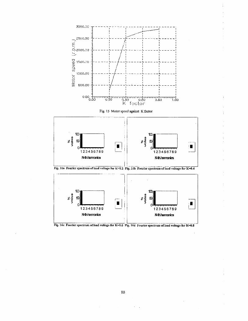
Fig. 15 Motor speed against K factor
LG. 1Ga Fourier spectrum of load voltage for K=O
ig. 16c Fourier spectrum of load voltage for K=0.6
m rig. 16b Fourier spectrum of load voltage for K=0.4
. 16d Fourier spectrum of load voltage for K=0.8