A Method to Estimate Weight and Dimensions of Aircraft Gas ... · PDF fileA Method to Estimate...
44
CR135171 A Method to Estimate Weight and Dimensions of Aircraft Gas Turbine Engines Final Report Volume II: User's Manual r < : -c -135171) ' [HCI r< TIM" IMEIGH1 ABD DIMENSIONS OF AI*CB»FT GAS 'TUHBISE ENGINES. VOLUME 2: US* Final Report (Boeing Co.. Seattle, Wash.) 42 D HC A03/HF 101 May 1977 N77-25172 Onclas 30U28 Boeing Military Airplane Development Seattle, Washington 98124 Prepared for National Aeronautics and Space Administration A NASA-Lewis Research Center Contract NAS3-19913 https://ntrs.nasa.gov/search.jsp?R=19770018228 2018-04-20T19:27:40+00:00Z
Transcript of A Method to Estimate Weight and Dimensions of Aircraft Gas ... · PDF fileA Method to Estimate...

CR135171
A Method to Estimate Weight and Dimensions ofAircraft Gas Turbine Engines
Final Report
Volume II: User's Manual
r < : -c -135171) ' [HCI r< TIM"IMEIGH1 ABD DIMENSIONS OF AI*CB»FT GAS'TUHBISE ENGINES. VOLUME 2: US*Final Report (Boeing Co.. Seattle, Wash.)42 D HC A03/HF 101
May 1977
N77-25172
Onclas30U28
Boeing Military Airplane Development
Seattle, Washington 98124
Prepared for
National Aeronautics and Space Administration A
NASA-Lewis Research Center
Contract NAS3-19913
https://ntrs.nasa.gov/search.jsp?R=19770018228 2018-04-20T19:27:40+00:00Z

1. Report No.
CR135171
2. Government Accession No. 3. Recipient's Catalog No.
4. Title and Subtitle
A Method to Estimate Weight and Dimensions ofAircraft Gas Turbine Engines—Final ReportVol II - Users Manual
5. Report DateMay 1977
6. Performing Organization Code
7. Authors
R. J. Pera, E. Onat, G. W. Klees, E. Tjonneland
8. Performing Organization Report No.
D6-44258
9. Performing Organization Name and Address
Boeing Military Airplane DevelopmentP. O. Box 3707Seattle, Washington, 98124
10. Work Unit No.
11. Contract or Grant No.NAS3-19913
12. Sponsoring Agency Name and Address
National Aeronautics & Space AdministrationWashington, D.C. 20546
13. Type of Report and Period CoveredContractor Report
14. Sponsoring Agency Code
15. Supplementary Notes Final Report (see also NASA CR135170 Method of Analysis and CR135172, Programmer's Manual)
Program Manager, Laurence Fishbach, Wind Tunnel and Flight Division,Mission Analysis Branch, NASA Lewis Research Center, Cleveland, Ohio
16. Abstract
A computerized method has been developed to estimate weight and en-velope dimensions of aircraft gas turbine engines within ±5% to 10%.The method is based on correlations of component weight and designfeatures of 29 data base engines. Rotating components are estimatedby a preliminary design procedure where blade geometry, operatingconditions, material properties, shaft speed, hub-tip ratio, etc.,are the primary independent variables used. The development andjustification of the method selected, the various methods of analysis,the use of the program, and a description of the input-output dataare discussed in this report.
17. Key Words (Suggested by Author(s))
Engine Weight Weight AnalysisGas Turbines Turbine EnginesAircraft Propulsion Computerized SimulationPrediction Analysis Techniques
18. Distribution Statement
Unclassified-Unlimited
19. Security Classif. (of this report)
Unclassified
20. Security Classif. (of this page)
Unclassified
21. No. of Pages
42
22. Price'
•For sale by the National Technical Information Service, Springfield, Virginia 22161

A MHTHOD TO ESTIMATE WEIGHT AND DIMENSIONS OF
AIRCRAFT GAS TURBINE ENGINES
Vol. II - Users Manual
By R. J. Pera, E. Onat,G. W. Klees, E. Tjonneland
1.0 INTRODUCTION
This user's manual for the WATE-1 computer program contains a description of input-output data,
values of typical inputs and sample cases. A description of the method and engineering analysis
is given in CR135170; the Fortran Listings are contained in CR135172.
WATE-1 is designed to function around a component-type engine cycle analysis program
NNEP(l). The calculated thermodynamic output data of NNEP is a necessary input to WATE-1
for component sizing. Use of NNEP is not described here since it is unchanged from its normal
mode of operation.
Normally, only the design point case of NNEP is used to generate the WATE-1 inputs. Addi-
tional NNEP off-design points may be desirable to define other WATE-1 inputs, such as maximum
shaft overspeed, or maximum operating temperature for each component. In order to produce
the most accurate weight estimate, the design case input data should encompass the maximum
performance level required of each component, i.e., maximum flow, work, speed, temperature.
All components that contribute weight must also be included in the NNEP engine model. WATE-1
will not calculate weight for components which are not included in the NNEP engine simulation.
WATE-1 has the ability to also accept an input weight sealer for each component so that selected
components can be increased or decreased (or eliminated altogether) to determine sensitivities,
etc. Both SI and English units of measure can be used.
LIST OF SYMBOLS
R
RPM -
TLP
Ut -
g
J
All
Nstage ~
Radius
Speed
Ut2/2gJAh/Nstage
Tip Speed
32.1415ft-lbf/sec2-lbm
778 BTU/lbm
Enthalpy Change
Number of Stages

2.0 PROGRAM STRUCTURE AND DECK STACKING
The overall program structure is shown in the flow chart, Figure 1. NNEP design point data is
stored in the "thermodynamic data" for use in calculating weights and dimensions (W/D) in the
WATE-1 part of the program. Computer execution time, core storage, and output print require-
ments have been increased slightly over the NNEP program.
The order of deck stacking of the Job Control cards and NNEP input data are unchanged from
the normal operation of NNEP. Two new inputs have been added to the NNEP indicator set.
The indicators, IWT = TRUE and IPLT = TRUE signals that the weight and dimensions calcula-
tions are to be performed, and the WATE-1 Data Set is required following the NNEP inputs.
Figure 2 shows a typical card-stacking arrangement necessary to operate NNEP and WATE-1.
3.0 WATE-1 INPUTS
The WATE-1 inputs are free-field format (NAMELIST), and begin in Column 2. There is no
specified order to the inputs; however, for the concurrence in the following discussion, they have
been grouped into Plot-Print Indicators, Length Indicators, Mechanical Design Indicators, and
Design Values. Figure 3 shows a complete input set for a typical case.
3.1 Plot-Print Indicators
IWT = TRUE - do weight calculation
FALSE — do not do weight calculation
IPLT - T
F
&wISII
ISI0
I0UTCD
I0UTCD
= T
F
= T
F
= 0
1
= 9
must be located in NNEPInputsand optional in WATE-1Inputs
— gas path layout
— no gas path layout
— placed at end of NNEP inputs to signal beginning of WATE-1 inputs
— SI units input
— English units input
— SI units output
— English units
— short form-engine weight, length, and maximum radius
— long form—component weights and dimensions and short form
— debug option and long and short form

NNEPINPUTS
THERMODYNAMICINPUT
NNEPTHERMODYNAMIC
PROGRAM
PERFORMANCEDATA
ARRAY
DESIGNPOINT
WATE-1 INPUTS
W/DINPUT
W/DPROGRAM
THERMODYNAMIC
DATA
1
GAS PATHDISPLAY
PROGRAM
GAS PATHDRAWING
Figure 1 Overall Program Structure
3

& END
IStl
KONFIG (1)
TITLE OF THE ENGINE
& w
END
-
(1)
/
WATE-IINPUTS
NNEPWITH IWT&IPLTINPUTS ADDED
Figure 2 Deck Stacking
4

MQUE 1 NOW BEING USED
IPLT=TIS11=F1SIU=FIJUTCJILLNGCi W M f c C (IWMEC(IWMEC(IwMEC(iwrtEC(Irt<MEC(I«MEC(IwMECiIwMEC(I*MfcC(IrfMEC(IrtMEC(Dt:SVALDESVALOESVALuESVALOcSVALDtSVALOcSVALDcSVALOESVALDESVALOESVALOcSVALUENU
,,,=111
tL
),
,=2
,3
2,3) = •) = •
,5,6,7FAN ,SPLT ,
1,4) = »UUCT ,1111
,
*,
5 )=•6 ) = »7) = »
,a ) = •
LPC ,P6UR ,HPT ,LPT ,
1 , 9 ) = »MI X ,i111(((((<((((
,,,,iii.iiA
11i1
i.0 ) =11) =12i,,,,
,,,,,,
J
2345.o
7^
T
=====•=====
10)11)
•JUCT1
•N02 ••SHAF*•SHAi=»• SsLt+i I15*0.,.45,2*.<*5,1.100.,..5,. 23.55, .2li*0.,=.1,2.
,81,
,91,
,14,
0,3*
11,0,
6*0,0,1,1,0,1,
5*2,
0,4* 0,
5*0,5,2,
-57,
,33*
*o,o,
0*0,,2,1,1,2.7
0.35
,*»,1,8,7, •
,1, •
*00,,4*
,3*0,3*045
1.70
,1
,1,1
0,,2,,5,.5,3.5,2.5,.45,C.,0.,l.,f. ,2.,!.,
1*0. ,•2,2.,1.5,.3,0.,0.,1.,0. ,2.,!.,
015,,143
,= 1.,14*0
( 1,12)=50000( 1,13) =50000
• »• »
.5,1
. ,
.3
.3
,1.5
,.,1
.5,2
853*
,1.5,.55,1!>UGUO.,3.,1.,6*0.,. , 3. , . 6 , 15 C 0 00 . , 3 . , 1 . , 6* C. ,
,12*0.,0. ,
Figures WATE-11nput
5

3.2 Length Indicators
The ILENG input specifies only those components that contribute to the total additive engine
length. The NNEP component number is specified in ILENG in the order that the components
would add in length to achieve the total length. This must start with the first compressor and
end with the furthest downstream nozzle. Figure 4 shows a typical engine and the ILENG inputs
for that engine. The ILENG input does not include duct (4), nozzle (5) or shafts (13) and (14)
because these components do not contribute to the total engine length.
ENGINE LAYOUT
t
13
on
m
14
C LJo n
n !9
r M
ILENG (1) = 1,2,3,6,7,8,9,10,11,12,
FLOW PATH AND COMPONENT NUMBERS
Figure 4 Length Input
6

3.3 Mechanical Design Indicators
The mechanical design indicators (IWMEC) must be specified for each component of the NNEP
simulation, with the exception of the NNEP Controls, Inlet, and Water Injection or any other
component not represented in WATE-1.
A number of shaft components may be required to simulate an engine in NNEP, as shown in Figure
5. WATE-1 will determine the weight only for connecting shafts of major components, such as the
typical HP or LP shaft. In the example of Figure 5, only shaft 15 and shaft 17 would be specified.
The smaller component number must always be used on the inner shaft, with increasing component
numbers as concentric shafts are added around the inner shaft.
IWMEC is a two-dimensional integer array that contains all of the mechanical design indicators. It
is of the form IWMEC (N, M), where M is the component number used in NNEP, and N is the vari-
able number as defined below for each component. Each variable in the IWMEC array for each
component is identified as shown in Figure 3 in free-field NAMELIST format.
10 12
1
c3
C
1 C 17
C \— SH
16
SH
T
J
14
T
OUTER SHAFT15
SHINNER SHAFT
IWMEC (1.15) =IWMEC (1,17) =
Figure 5 Shaft Input
7

3.1.1 Compressors
IWMEC ArrayLocation
1
6
7
Description
Type of compressor being weighed.
'FAN' - Typical fan
'F(/>' - Outer portion of non-rotating splitter fan
'FI' — Inner portion of non-rotating splitter fan
'RSF0' — Outer portion of rotating splitter fan
'RSFI' - Inner portion of rotating splitter fan
'LPC - Low pressure compressor
'HPC - High pressure compressor
This indicates if the fan or compressor has stators.
1 - Stator weight is calculated
0 - Stator weight is not calculated
This is the indicator for 'front' frames in compressors. This input may be:
0
1
2
4
— No frame
- Single bearing frame for turbofans and turbojets withoutPower Takeoff (PTO)
— Single bearing frame with PTO
— Two bearing frame, such as the frame in front of the HPCin the JT8D or JT9D which extends outward to the fanouter case and holds two bearings with PTO
This is the indicator for the 'rear' frame in a compressor.
0
1
2
4
— No frame
— Single bearing frame for turbofans and turbojet withoutPower Takeoff (PTO)
— Single bearing frame with PTO
— Two bearing frame, such as the frame in front of the HPCin the JT8D or JT9D which extends outward to the fanouter case and holds two bearings with PTO
This is the component number connecting to this component for splitflow compressors only. If this is the Fan Outer, the Fan Inner must bespecified. If this is the Rotating Splitter Outer, the inner splitter must bespecified, and vice versa.
Gear box indicator — 0 — No gear or component number of shaft
Number of stages

3.3.2 Turbines
Location
1
3
4
Description
This is the type of turbine.
'HPT' - High pressure turbine
'LPT — Low pressure turbine
Indicator for turbine exit frame.
0 — No frame
1 - Frame
Compressor number from which the RPM is determined
Component number from which the outer radius limit for the turbine isdetermined. If the component number is positive, the outlet dimension isused. If negative, the inlet dimension is used. If 0, it will use the outletof the feeding component.
Number of stages
3.3.3 Burners
Location
1
Description
This is the type of burner being weighed. The input is the burner namein four spaces.
'PBUR' — Primary burner (airframe will be included)
'DBUR' — Duct burner (a mean radius is specified)
'AUG' - Augmentor (no inner wall)
This is the indicator for frame weight, normally only for primary burners.This frame includes a bearing.
0
1
— No frame
— Frame
3.3.4 Ducts
Location
1
9
Description
Input 'DUCT'
Indicator as to type of duct
1 — Dummy — i.e., no weight or length
2 — Length input
3 — Length derived as in a duct connecting a splitter and amixer

3.3.5 Shafts
Location
1
2
3-6
Description
'SHAF' - Standard shaft
Shaft number from inner to outer, i.e., 1, 2, 3, 4 or 5
Turbine numbers connected to this shaft. The last entry is the furthestdownstream turbine. This is used for power summation.
First upstream compressor connected to the shaft
3.3.6 Mixers
Location Description
Type of mixer
'MIX' — The coannular emergence of two streams without mechani-cal mixer
'FMIX' - Forced mixer, mechanical, i.e., Daisy lobed mixer
Indicator for primary input node
0 — Primary is inner
1 - Primary is outer
3.3.7 Nozzles
Location
1
2
Location
3
Description
'NOZ' - Input
Nozzle type
1 - Convergent
2 - C-D variable area
Description
Component number from which the nozzle inlet diameter can be deter-mined. If this diameter is taken from the inlet of the component, the(-) component number must be entered. If (+), the exit node will beused. If the previous component determines the diameter, this locationmay be zero.
Thrust reverser type
0 - None
1 — Fan
— Primary
10

3.3.8 Splitters
Location Description
1 'SPLT' - Input
2 1 - If inner stream is not primary
3.3.9 Annulus Inverting Valve
Location Description
1 Input 'VALV
2 Location of Valve
1 — Inner
2 - Outer
3 Component Number of Opposite Duct
4 0 If Fixed, 1 If Movable
3.3.10 Heat Exchangers
Location Description
1 Input 'HTEX'
2 Type
1 - Fixed Tube
2 - Rotary
3 Flow Direction
1 - Parallel Flow
2 — Counter Flow
3.4 Design Values
This section contains the mechanical and aerodynamic design data necessary to determine the
weight and dimensions of each component. A summary of this array is shown in Table 1. If
desired, the default values, Table 2, can be used for any component by not specifying the inputs
for that component. The data required is in the floating-point two-dimensional array DESVAL
(N, M), where M is the component number from NNEP and N is as defined below. A typical set of
inputs is shown in Figure 3, and a typical range of values is shown in Table 3.
11

The calculated component weight can be adjusted by an input sealer, DESVAL (15, M), which is a
factor applied to the calculated weight. A zero value, however, denotes that no scaling is used. If
it is desired to zero-out the weight of a component, the sealer can be set to a trivial quanti ty such as
.0001.
Table 1 DESVAL/DEFAUL Array
\vRDSITION
TYPE^^^
COMP
TURB
BURN
DUCTS
TRAM/SHAFTS
MIXERS
AIV
HEATEX
NOZ
SPLT
1
MNI
MNI
VR
MACH
STRESS
L/H
L/H
#TUBE
L/D
MNI
2
PRM
TLP*
TR
L/H
RHO
NO. PASS
NO. PASS
MNIP
H/T
3
H/T
SOLID
DIAMEAN
DIAMEAN
H/T
MNI
MNIS
4
SOLID
ARI
REFLOC
REFLOC
MNO
BPR
5
ARI
ARO
RH
6
ARO
MNO
WTIC
7
MNO
REFSTR.2% YIELDSTRESS FORDISK
WTOC
8
TMAXI
MODE
WTW
•TLP =
h/NSTAGES
""""-^POSITION
TYPE^^"\^
COMP
TURB
BURN
DUCTS
SHAFTS
MIXERS
AIV
HEATEX
NOZ
9
TMAXO
RPMR
10
RPMR
11
RHO BLADE
12
MODE
13
RPMSC
14
TMET
15
WEIGHTSCALER
12

Table 2 DEFA UL Array
TYPE
FAN
LPC
HPC
HPT
LPT
PBUR
DBUR
AUG
DUCT
SHAFT
MIXERS
NOZAIVHTEX
1
.55
.5
.4
.3
.45
100.
150.
300.
.4
50000.
1.
1.1.
5000.
2
1.7
1.5
1.4
.25
.25
.015
.015
.015
1.
.286
8.
14*0.8.
.5
3
.45
.4
.7
1.5
1.5
13*0.
13*0.
13*0.
0.
13*0.
13*0.
.5,5
4
1.5
1.5
1.5
1.5
2.
-1.
.5
5
4.
4.
3.
1.5
4.
11*0.
1.1
6
3.
3.
1.5
.45
.55
1.1
7
.45
.45
.3
125000.
125000.
1.1
8
0.
0.
0.
2.
2.
9
0.
0
0.
1.
1.
10
1.11.0
6*0.
6*0.
11
2.
0
0.
12
1.
?
2
13
0.
1
1,
14
0.
na
16
0.
n0.
Table 3. Typical Range of Input Values for DESVAL/DEFAUL
TYPE
FAN
LPC
HPC
HPT
LPT
PBUR
DBUR
AUG
DUCB
SHAFB
MIXERS
NOZAIVHTEX
1
.5-.6
.45-.6
.4-.5
.3-.4
.4-.5
100-150
1 50-200
200-300
.4-.5
40-50 KSI
1.-2.
1.-2..8-1.25000.
2
1.5-1.8
1.5-1.8
1.4-1.7
.2-.3
.1-.3
.01 -.02
.01 -.02
.01 -.02
*
.28-.31
7.-9.
6.- 1Q..3-.5
3 .
.4-. 5
.4-.5
.6-.8
1.-1.5
1.-1.5
*
*
0.
*
0.-.85
.4-.6
.S-.5
4
1.-1.5
1.-1.5
1.-1.5
1.-2.
2.-3.
*
«
*
*
.4-.6»
5
3.-5.
3.-5.
2.-5.
1.-2.
4.-6.
*
6
2.-3.
2.-3.
1.-2.
.45-.5
.55-.6
*
7
.45-.55
.45-.55
.2-.3
100 KSI150 KSI100 KSI150 KSI
8
0.
0.
0.
*
*
*
9
0.
0.
0.
1.
1.
10
1.1.1.0.
11
0.
0.
0.
0.
12
*
*
*
0.
13
1.
1.
1.
0.
14
0.
0.
0.
0.
15
*
*
*
'NOT APPLICABLE - SEE TEXT
13

3.4.1 Compressor
ArrayLocation
1
2
3
4
5
6
7
8
10
11
12
13
14
15
Description
Compressor face inlet Mach number
Maximum first stage pressure ratio
Compressor face hub-tip ratio —
Blade solidity, ratio of blade cord to blade spacing
Blade aspect ratio at first stage
Blade aspect ratio at last stage
Compressor exit Mach number
Maximum compressor inlet temperature. ZERO If design point temperatureis to be used for material selection °R, °K.
Maximum compressor outlet temperature. ZERO If design point temperatureis to be used for material selection °R> °K.
Maximum speed ratio - RPMj^ax/RPMfjesign
Blade material density. ZERO If WATE-1 is to select material.Ib/in3, Kg/cc compressor design type
1. Constant hub radius design
2. Constant mean radius design
3. Constant tip radius design
RPM, sealer, normal input is 1. — use to match known RPM of engine
Temperature at which a change of material is required. If ZERO 1160°Rwill be used, °R, °K.
Compressor weight sealer, input ZERO If no scaling is desired.
3.4.2 Turbines
Location
1
2
3
4
5
6
7
Description
Turbine face inlet Mach number
Turbine loading parameter
UT2/2gJ h/Nstages
Blade solidity blade cord/blade spacing
Blade aspect ratio of first stage
Blade aspect ratio of last stage
Turbine exit Mach number
Disk reference stress — .2% yield, this selects disk material.Ib/in2, Newton's/cm^
14

9
10
11
12-14
15
Turbine design type
1 . Constant tip radius design
2. Constant mean radius design
3. Constant hub radius design
Maximum speed ratio — RPMj^
Turbine control radius inches/cm — blank if transferred from a component
Density of material in turbine blades -
Turbine weight sealer, input ZERO.— If no scaling is desired.
3.4.3 Burners
Location
1
2
3
5-14
15
Description
Burner through-flow velocity, ft/sec, m/sec.
Burner airflow residency time, sec.
Burner mean diameter, in. or cm. If zero, diameter is calculated to matchconnecting component.
Component number for calculating mean burner diameter. Enter zero ifdiameter is specified.
Not used.
Burner weight sealer, enter ZERO.—If no scaling is desired.
3.4.4 Ducts
Location
1
2
3
5-14
15
Description
Duct Mach number.
Length to height ratio of duct, required if mode 2 is used in IWMEC.
Duct mean diameter, in. or cm. If 0., duct diameter is calculated based onnode specified below.
Node number to calculate mean diameter. Enter 0, if mean diameter isspecified. Enter -1, if connecting component is to be used.
Not used.
Weight sealer, ZERO.-if no scaling is desired.
15

3.4.5 Shafts
Location
1
2
3
4-14
15
Description
Shaft allowable stress. Ib/in2, Newton's/cm2
Shaft material density. Ib/in3, Kg/cc
Diameter ratio of shaft Djnner/Douter.
Not used.
Shaft weight sealer. ZERO If no scaling desired.
3.4.6 Mixers
Location
1
2
3-14
15
Description
Effective length to diameter ratio of mechanical mixer, L/ 2A/vr ,where L is the mixer length inlet to exit, A is the total flow area. Enter0. if not a mechanical (forced) mixer.
Number of passages (or lobes) in mixer.
Not used.
Weight sealer. Enter ZERO, if no scaling is used.
3.4.7 Nozzles
1
2
3-14
15
Length to diameter ratio of nozzle
Bypass ratio for mixed flow nozzle for T/R weight.
Not used.
Weight sealer. ZERO, if no scaling desired.
3.4.8 Splitters
Location
2
3-14
15
Description
Only input if first calculated component in flow path.Mach number in.
H/T ratio in.
Blank.
Weight sealer.
16

3.4.9 Annulus Inverting Valve
Location Description
1 Specific length - L/ \#A/7r
2 Number of passages.
3 Mach number of inner.
4 Mach number of outer.
5 Hub radius in inches/cm or - component number from which hub radiusis taken or blank if feeding component determines the hub radius.
6 Inner cylinder weight —
7 Outer cylinder weight — lb/ft2/Kg/m2.
8 Wall weight - lb/ft3/Kg/m2.
9-14 Blank.
1 5 Weight sealer.
3.4.10 Heat Exchangers
Location Description
1 Number of tubes if "Fixed" type.
2 Mach number in primary stream.
3 Mach number in secondary stream.
4 Engine Bypass ratio if "Rotary" type.
4.0 PROGRAM OUTPUT
The output from WATE-1 may be selected in any of three output formats. Either English or SI
units can be selected. Examples of the output for the sample case, Figure 3, are shown for the
short output in Figure 6, the long form, Figure 7, and the debug output, Figure 8. This output
shows the mechanical design and weight breakdown within the individual component. The units in
the output section are shown in Table 4 for English and SI units. The type of units used are noted
in the units section of the output.
A flow path layout is also available for conventional type engines. A typical layout is shown in
Figure 9. The layout is scaled such that it will fit on one page of the output.
17

1GIAL uAKt ti^GliMfc Wt lGHT= 2 Vl i.. AC Lt SSUkltS= 2 62 .0 2
E S T I M A T E D TuTAL LENGTH= 2J6. ESTIMATED MAXIMUM KADIUS
FigureG Short Output
WEIGHT INPUT DATA IN ENGL UNITSHEIGHT OUTPUT DATA IN ENGL UNITS
CuHP WTNO
1234567a9
10111213
cST
G.1029.
0.29.
616.250.126.4o9.
0.^6.
295.<»0.It.
COMPL t N
0.29.
0 •62.25.18.5 .
13.0.
58.58.0.0.
ACCULEN
0.29.29.91.54.72 .78.91.91.
149.2C6.
0.0.
U P S T R E A M RADIUSRI
0.9.C.
16.9.9.
10.9.4.0.C.9.9.
RQ
0.2:0.0.
Id.13.13.ii.12.16.
29.iV.20.13.
Rl
0.0.G.0.C.0.0.G.
16.0.G.
1G.0.
RO
0.0.0.0.0.0.0.0.
21.0.G.
11.0.
DOWR I
0.13.13.16.11.V.
10.9.4.0.G.0.0.
N S T R E A M R A D I U SRO
0.18.16.18.11.13.13.14.21.29.27.0.0.
R I
0.0.
16.0.0.0.0.0.0.0.0.0.0.
RO
0.0.
18.0.0.0.0.0.0.0.0.0.0.
NSTAGE
0300
1002200000
TOIAL BARE ENGINE WE1GHT= 2915. ACCESSQRIES= 262.02
ESTIMATED TOTAL LENGTH= 206. ESTIMATED MAXIMUM RADIUS = 29.
Figure 7 Long Output
18

REPBODUC1BIL1TY OF THEORIGINAL PAGE JS POOR
************** ** H-AN 2 *
* *************2DUCT
M NO VtL T TOT P TOT P STAl ARtA GAM0.524 570. 519. 1905. 1579. 6.9517 1.4005
U TIP STRESS DEN W/AREA TR H/T1258.9 26757.6 0.168 2.339 1.800 0.450
COMPRESSOR 2 MECHANICAL DESIGN
LOADING N STG DIAM U TIP C RPM C RPMO.b74 3.00 39.98 1258.9 7216.9 7216.9
FKAMc WT = 95.67
STAGE 1WD WB WS WN WC CL RHOB RHOD AR65. 5V. 59. 0. 26. 7.4 0.168 0.168 3.50
PR UEL H MACH A R t A K MU8 R TIP Nb U TIP STR WEIGHT TIN1.4789 16.7 0.524 6.952 8.99 19.VV 591256.9 26758. 209. 519.
STAGE 2WD WB WS WN WC CL RHOB RHDD AR
91. 34. 34. 51. 21. 6.2 0.168 0.168 3.00PK JbL H MACH A R t A K HUB R TIP NB U TIP STR WEIGHT TIN
1.4155 16.7 0.4V9 5.180 11.02 lb.9^ fc7 1193.2 20191. 231. 588.
STAGE 3WD wB WS WN WC CL KHOb RHOD AR
V7. 2J. 23. 46. 19. 5.7 0.168 u.168 2.50PR UEL H MACH ARtA R HUB R TIP NB t TIP STR WEIGHT TIN
I,3o7l 16.7 0.475 4.017 12.17 18.23 70 1148.1 15768. 208. 658.
FRAME WT = 2r,5.15
N STG «£ll»HT LENGTH3 1028.68 28.80
DUCTM NO VcL T TOT P TOT P STAT AREA GAM
0.450 t>b2. 727. 5447. 4743. 3.2206 1.3951
PR AO EF PO TO HP2.8600 0.8700 5447.2 726.9 16910.
HI HC WI CWI123.95 174.07 238.50 265.OC
******************* TOTAL COMP WEIGHT IS 1028.680
Figure 8 Debug Output
19

************** ** HPC 5 *
* *************2DUCT
M NO VfcL T TOT P TOT P S F A T Ak tA GAM0.450 5b2. 727. 5447. 4743. 1.6196 1.3951
U TIP STRESS DEN W / A R E A TR H/T1265.1 23331.5 0.168 C. 68 7 1.200 C.700
CUMPRbSSGR 5 MECHANICAL DESIGN
LOADING N SFG OIAM U TIP C RPM C RPM0.651 IG.Ou 25.58 1065.6 11515.5 9727.5
FRAME WT = 118.22
STAGE 1WD WB WS WN WC CL RHUB RHJD AR
^4. 14. 1*. 36. 10. 4.5 O.lbd 0.168 2.00
PR DtL H MACH ARtA R HUB R TIP NB U TIP STR WEIGHT TIN1.3603 17.0 O.*»50 1.320 3.9a 12.79 50 1285.1 23331. 99. 727,
STAGE 2WD WE WS WN WC CL RHQd kHOD AR
*:0. 9. 9. 29. it. 3.6 0.160 0.168 1.94Kk DtL H MACH A R t A R HUB k TIP Nb U TIP STR WEIGHT TIN
1.3.141 17.6 0.435 1.442 9.42 1^.45 to C 125C.7 18516. 75. 800.
STAGE 3WD «b WS WN WC CL KHOB RHOD AR
lt>. 6. 6. 25. 7. 3.0 0.163 0.166 1.89KK u£L H MACH A R t A it HUB R TIP NB U TIP STR WEIGHT TIN
17.a 0.420 1.171 9.75 12.19 7C 1225.3 15046. 59. 873.
S I AGE 4WD WB WS WN WC CL RhOo KHOD AR
13. 4. 4. 21. 6. 2.6 0.168 O.lob 1.83PK DtL H MACH ARtA R HUB R TIP NB U TIP STR WEIGHT TIN
1.270H 17.6 C.HOi 0.970 9.96 1^.00 bl 1206.2 12477. 49. 94t>,t
STAGE 5WJ MB WS WN WC CL KHOB RHOD AR
11. 3. 3. 18. 5. 2.2 0.16d 0.168 1.78Pk DEu H MACH AREA k HUB R Tl P Nb U TIP STR WEIGHT TIN
1.2499 17.8 0.390 0.816 10.15 11.86 93 1191.5 10527. 41. 1017.
STAGE 6MD WB WS WN WC CL RHOB RHOD AR
10. 3. 3. 16. 4. 2.0 0.168 0.166 1.72PR DEL H MACH AREA K HUB R TIP NB U TIP STR WEIGHT TIN
17.6 0.3Y5 0.701 10.28 11.74 104 1180.1 9018. 36. 1069.
Figured Cont.
20

STAGE 7WD WB WS WN WC CL RHOb HhOO AR9. 2. 2. 14. 4. 1*8 0.166 0.168 1.67PR utL H M A C H A R f c A K HU6 R TIP !"4b U TIP
1.2173 17.d 0.360 0.608 10.39 11.65 115 1171.0STR W E I G H T TIN7829. 32. 1159,
SI AGE 8WD Wb WS WN WC CL RHOB KHOD AR
1C. 3. 3. 13. 3. 1*6 0.286 0.286 1.61PK UfcL H M A C H A R t A R HUB R TIP NB U TIP STR W E I G H T TIN
l.<.04<_ 17.t 0.345 0.534 10.47 11.58 126 1163.6 11712. 39. 1229,
ST AGE 9WO Wb WS WN WC CL RHOB RHOO AR
15. 3. 3. 12. 3. 1.5 0.286 0.286 1.56PR L>tL H M A C H A R t A R HUB R TIP NB U TIP STR W E I G H T TIN
1.1926 17.b v>.330 0.475 10.53 11.52 1361157.7 10407. 36. 1299,
S T A G E 10WU Wb WS WN WC CL RHOb RHOL AR
15. c. 2. 11. 3. 1.4 0.2fa& 0.286 1.50PR UtL H M A C H A R E A R HUB R TIP NB U TIP STR
1.18Z<* 17.b 0.315 0.426 10.59 11.47 146 1152.8 9343. 33. 1367,W E I G H T T I N
N STG
10
DUCTM NO
0.3UO
WEIGHT
616.4J
LtNGTH
25.43
VEL T TOT P TOT:>1236.
P STAT ARfcA GAM43231. 0.3874 1.353V
PR AU tF PO TO HP9.406U O.b700 51235.9 1435.6 33965.
HI HO rtl CW1174.07 352.23 134.75 61.97
*****»***********«' T O T A L C3MP WEIGHT IS 616.477
*****#******«
*» PBUR
*«***«
***
RIN ROUT LENGTHb. ?5b
CAS WT24.2
12.909LIN WT
40.4
18.000NOZ W.T
17.8
MACH0.055
INC WT16.4
WSPtC4.59t>FRAME151.3
WTOT250.2
Figure 8 Cont.
21

HPT
DUCTrt NO VtL T TOT P TOT P S T A T AREA GAM
0.500 lido. 2621. *6112. 39327. 0.3977 1.2968
U TIP STRESS DbIM W / A R E A TK H/TllGo.O 9819.5 0.286 C.246 1.000 0.922
TURBINE 7 MECHANICAL UtSIGNH/T N STG LOADING A R E A
0.922 2.000 0.280 0.398UT KT1P RHUB DEL H RPM TORC
1106.0 11.0 10.1 174.5. 11515.5 185913.
STA^E 1L/ISK BLAUE VANE HWD C A S E AR
o.t 2.3 8.4 21.7 4.0 1.50PK UEL H MACH A R E A k HUB R TIP MB U TIP STR WEIGHT LENGTH
1.8453 67.3 0.500 0.398 10. 14 11.01 IbO 1106.0 9820. 42.84 2.02
ST AOE 2DISK bLADt VANc HWD C A S E AK
10.8 o.4 23.7 35.5 6.d 1.50PK Utu H MACH ARtA R HUB R TIP NB U TIP STR WEIGHT LENGTH
a7.^ J.525 0.666 10.14 11. i-^ 1161160.9 16456. 83.19 3.29
N STG LENGTH WEIGHT2 5.31 126.03
DUCTM NO VtL T TOT P TOT P STAT ARtA GAM
0.5-jG 1149. 2J28. 12436. 10243. 1.2074 1.3127
PR TR AD EF PO TO TG.l3.7081 1.2928 0.8600 12435.6 2027.7 2027.7ri IN H OUT AREA FLOW HP
524.74 5.17 1^7.56 JJ969.
TOTAL TURB WEIGHT IS 126.028
** LPT
DUCTM NO VtL T TOT P TOT P STAT ARtA GAM
11<*9. 2028. 12438. 10245. 1.2072 1.3121
Figures Com.
22

U TIP7<i 7.0
TURBlNtH/l
0.765UT
727.0
bTRESS11706.5
DEN0.286
6 MECHANICALN Sib LOADING2.000 0.243
RHP RHUb11.5 8.8
W/AREAC.777
DE SI GNA R E A
1.207DEL H86.9
TR1.000
H/TG.765
RPM7216.9 147693.
STAGE 1DiSK bLADt VANt HWD C A S E AR
5.0 22. •» 66.0 38.9 S.v ^.COPK utL H rtACH A R E A k HUB k TIP NB U TIP STR WEIGHT LENGTH
-*3.<* U.550 1.207 8.83 11.^4 bC 727. C 11709. 142.18 4.77
STAGE 2L»iSK bLADb VANE HtfD CASb Ak
6.V 27.6 81.4 34.0 9.3 3.00Pit DEL H MACH ARhA R HUB R TIP NB J TIP STR WEIGHT LENGTH
l.i.156 43.4 u.57:> 1.652 8.d3 i2.^9 96 780.6 16019. 159.21 4.17
FRAME rtT = 167.79
N STL, LtNGTH WEIGHT2 13. Hi <»69.1S
DUCTM NO VtL 1 TOT P TOT
0.600 lii><t. 1722. 5594.P STAT AKcA GAM4436. 2.3313 1.3249
PR TR AD EF PO TO TC.l2.2236 1.1779 J.StoOO 5593.7 i/21.5 1721.5H IN rt OUT AREA FLOW HP524.77 <»37.dY 16.80 137.56 16912.
TOTAL TURB WEIGHT IS 469.184
**+****»****** ** AUG 10 *
* *
BURNER NUMBER 10R1N ROUT LENGTH MACH WSPfcC0.0 24.120 48.000 0.1*3 11.899
LAS WT LIN WT NOZ WT INC WT WTOT23.7 12C.O 296.1 0.0 43V.8
Figure 8 Cont.
23

************** ** NOZ 11 ** ****«********?NlUZLt 11
568. L ENGT H= TK Wl = 0.0
*****««****«*
* ** DUC I 4 ** *************2DoCT , 4Rrt = 1^.78 RT= 17.69 LENG= o2.l6AKEA= 1.4C1 RHQ=.l6d
CAS WT INC WT WTOT
*» ************ . ** SHAf 12 *
* *
SHAFT00
3.5*Dl
3.01LENG ON WT48.74 0.65 40.03
************** ** SriAF 13 *
* *********** **2SHAFT 13
00 Ul LENG4.35 3.94 18.CC
DN WT1.27 14.33
** ************ ** A C C S *T *
* **» ***# ******2
ACCS WT= 301.414
Figure 8 Com.
24

WEIGHTWEIGHT (
CuMKNu
JH
t>
7B
1C111213
wTtST
0.1132.
0.32.
o78.21$.
0.HUH.
t>2o.4H.
16.
UT UATAJT DATA
ININ
GUMP ACCULfcN
0.29.0.
62.25.id.
5>.13.0.
48. 148. 10.0 .
LEN
0.29.29.91.54.72.78.91.91.39.87.0.0 .
ENGLENGL
URl
0.9.0.
16.9.9.
10.9.4.0.0.9.9.
UNITSUNITS
PSTKEAMKG
C.20.0.
18.1 J.13.11.12 .16.2H.
2n.20.13.
RADRI
0.0.0.0.c.c.0.0.
16.0.c.
1C.0.
I USRO
0.0.0.0.c.0.0.0.
21.0.C.
11.0.
DOWNSTREAM RADIUSR I RO RI RO
0.13.13.16.11.9.
10.9.A.0.C.O.0.
0.18.16.18.11.13.13.IH.21.24.22.0.0.
0.0.
16.0.0.0.0.0.0.0.0.0.0.
0.0.
18.0.0.0.0.0.0.0.0.0.0.
TOTAL bARE ENGINE WEIGHT= 3941. ACCtSSORIES= 3C1 .41
ESTIMATED TOTAL LENGTH= Id7. ESTIMATED MAXIMUM RADIUS* 24.
NSTAGE
0300
1002200000
Figures. Cont.
25

UPLtAIEu INPUf OATA TO kEFLtCl LALCULATED INPUT
to0\
MO. IT re
l INLfcf
I S K L U I f c K-. OUCT B
L, UJLl 3
1 TuRolNEJ TUkolNE•» MlAtK
it- uucr »
ii SHAM
OAF1NP1 LAUNCH0.^38300 03 0.0v.lbOOGo 01 O.uu. 770000 00 C.C0.0 0.0t. l30i.au 01 u.26U<OU-OlU.10300U Ob 0.00.4uuOv>D 01 0. lOUoub 01
j . /Of7.JD 03 0.63925J 330.600uOJ— 01 0. u0.4/ibHb f i C . i O C C C u 01O.tOOOOb C-.
i., bMAFI j.oJOGOi) 04
C A S t L I ULNf IhlLAUON
rLG*iTAl lJN
1i%'jo/
b<y
1C1 \\L131411.
NU. TV PCi. INLtl^ CJrtPKLiKJ S P l l T l c H4 DUCT da wJlrHt^k6 OUC1 B/ lUKOlNfc0 TUrlolNt
» MlAErt
lu uuCT dil NjIiLt!<. SHAI-t
1 J ^rl AF 1
HE 1 OUTFLO*
S T A T P lU.<.3A500C.23b>ul>0 .1:30500j.t3475J0. 131<.4C>3.350^400. 134 05 u0.13756U0.1375ou0.1 J3 7su0.241 il U0.241 3100.241 3100. 10375 u
OATOUr iO.u
-0.16912U0.7700000.0
->j.33voVO0.00.33vo9o0.16V 1200.70O30O.u0.137U5J0.0
0.0
(.. IOOC.0^ Jl0. iO OC Ju u 1
UATINP30.146960 02
C.OC.O
clc0.407330 00u.Jl-577J 003.i-»OO!iU C'O0.00 . L
0.1T".OuL 01O.iCOOoC 01
DATINP4 DATINP5C.O 0.00.37olOD 04 0.265900 03C.O 0.0C.O 0.00.3707CU 04 0.61413D 02(.265000 04 C. 940(00 OC0.380100 04 0.706450 COC.3U030D 04 0.726330 OCC.O 0.00.0 3. 9 CO 00 J 00o.o o.vauoop ocr.iouooj 01 o.iooooo 010.100JOJ 01 0.100000 01
DAT1NP60.900000 000.37620D 040.00.00.370800 04C.lb30CO C50.3bl)20D 040.300400 040.00.183000 05C.lCCCOu 01C. 1COOOD Cl0.10JOOO 01
OATINP7O.C0.101130O.CC.O0.9090900.0C.V672700. 940 1200.0O.C0.0C. 1000000.100000
01
00
0000
0101
UAT1NPU0.0 00.376300 C4 0O.C 0C.O 00.270900 04 00.0 0O.VC244D CO 00.81556b 00 00.0 00.0 00.0 0C. 1CCOCD 01 00.10000D 01 C
OATINP9.0.992220.0.0.132460.0.ICCGOb.100000.C.0.100000.10CCCO.100000
CO
01
Cl01
010101
SIMPLE MuotL
0303030303010303030303030303
Ca00
03
030503
05
KAvrt* o.- A L T l I O O t =
Al Ki-LOrf (L3/Ncl 11-IKw.iTIJ lAL J . « L = T
itC)
DKAbl .»M»LLcu It tKJST
T O T A LPRESSURE
STATP lG.1HM6U Otu.i3226L> j20.3/d^db OJ0.37b2bb 'J2C.J5581J v..>0.35531L) 030. 32Ci2b 03C.boiVo^ uiC.3oUtVu 3to .SVu^BO 020. i7401u JiO.J>5 15 lu 320.35l57o 0^C..j7b2Bb i' 2
OATJJIiO.u
C . *»0 tr o*> 0 4C.C0.0C.oOC»uu 040. 10010J 30O.bOOaOJ u4C . 4 0 C ' t O 040.63v^5j 030.600000-uJLO.V337MJ U4G.40000U 04
C.cCC.C. C v
o . r>
.Jb.jJ13 /J3. -1
C . C»37o5.o i
£
T O T A LTEMPER A TUKE
iTATP30.51B«>rJ C^0.51d67L 03O. 7^6370 C30.726870 03•0. 143560 04O.K3560 C4O.^ f tSOOD 04J. <ri27b J 04c..ir^i6b 040.726670 03O.ijl5/0 040. 131570 040.13157u 04C.7i687L) OJ
1./TOUT3O.t,O.I.3.00.00.00.00.1COOOD 01r.icoooo 01C.103B7U 010.00.iJ92iD 01
TATIC .N PR3PEK1Y OUTPUT D A T A
FUEL/AIR REFERREDRATIO FLOW
STATP4 S1ATP5C.C C.2385CO 030.0 0.264VVL) 03C.O 0.1C9b9D C30.0 0.6197CO 02O.C 0.901830 01C.O 0.0C.»1425D-01 0.139060 02C.208oBD-01 0.46276U 020.208680-trl 0.948010 020.0 O.O717J 020.117900-01 0.15101J 03C.11790u-Pl 0.160650 33C. 117*00-01 0.160650 03O.C 0.477170 02
COMPONENT OUTPUT O A T A
LIATOUT4 JATCHJT5C.lOOOOu 01 0.100000 01C. 180000 01 0.400000 040.0 0.00.0 0.00.130000 31 0.514550 040.214250-31 0.0C.40000J 01 0.467330 000.250uOO 01 0.385770 000.10U4D 01 0.472740 030.0 0.00.483930 33 0.472830 03
0.4o.?OuD 04 C.40000J 04 0.0
r.tc 'cc j 04
. L C J V t R Y = i;.v
V,KUSS Trtkb
TiK
C.6UCGU 04 O.D
COO 0 l l tRATIONi
ST 13Vd5. r< l0. V 3 4 3
T u T A L Jr<A^L Sl-IAFT nt> C.CJ N i T A L L L b TSK C..734?
MACHNUMoEKSTATP6
0.0O.CC.C0.00.0C.O0.00.00 .24CCCD CC0.0C.OO.lOOOuU Jl0.11729D Cl0.127340 00
OATOUT6G.C0.100000 01C.C0.30.985000 000.1C1230 05G. 568000 040.524400 040.167730 C30.00.10000D 010.0
C.O
, PA^L,
FUtL FLJKNfcl TnkoSSuAdi lLS P H L A C - c
S T A T I CPRESSURE
STATP7C.C.0 .0C.O0.00.0C.OC.OO.dC.374C100.0C.O0.18780D0.1469600.374010
OATOUT7G.VOOOODC. 265 9000.0O.CC. 6141800.00.7064500.726330C.O0.3O.v 800000.0
...
(Ln/MK )T/A IK FLOWuKAL» L JP 'JR4G
INTERFACE CUKKfcCT
C2
020202
0003
02
0000
00
F L O W EKfcOKSTATPb
0.00.00.0C.O0.0C.OC.O0.00.00.00.0u.OC.CO.C
DATOUTfc0.1GOOOD 01 00.870000 00 0C.O 0c.o oO.b7000b CO 0.O.V40000 CO 00.8oOOOD 00 00.860000 00 0C. 949900-16 C0.0 00.187210 01 00.0 0
C. C C
101^2. tlS7. /•*(!!<
v. CC. C
bb
DATOUT9.C.286000.0.0.940 60 D.265000.370730.122340.lOOOuO.0.239230.0
.0
01
0104010101
01
Figure 8 Com.

A A A A A A A A ) A A A A A A A A A A A A A A A A A A A A A A A A N N N
CCCLC
c CCLCCCCCCC.LCLCCc V.V.L-I.V.CLCCCC c-CC CCCv-CCC
KPPPPPPPP T T 7 T T T T T TT I T T T T T
PPPPPPP T T T T T T T T T T T
c/L C/L C/L C/L C/L C/L C/L C/L /L C/L C/L C/L I./L C/L C/L
N)
Figure 9 Flow Path

Table 4. Output Units
VARIABLE
Velocity
Temperature
Pressure
Area
Stress
Density
Weight
Length
Enthalpy
Horsepower
Weight flow
Weight flow/unit area
Radius
SI UNITS
m/sec
°K
n/m2
M2
N/cm2
kg/ cm
kg
cm
kwatts
kwatts
kg/sec2
kg/m sec
cm
ENGLISH UNITS
ft/sec
°R
lb/ft2
ft2
lb/in2
.lb/in3
Ib
in
btu/sec
hp
Ib/sec
lb/ft2 sec
in
28

5.0 EXAMPLE CASE
A simple mixed flow augmented turbofan is used as an example for the WATE-1 input and execu-
tion. Figure 10 shows a schematic and a block diagram of the engine. From this block diagram, the
component numbers are determined.
11
?
2 3
" 4 " -
11
12
H
5/
6
7
1C
SH
8
1
\1
7
r
15
91
I9 10 11
12 138
r10
14
Figure 10 Engine Schematic
29

To construct the input deck the indicator section must first be set, Figure 11. In this example, the
units in and out are English, so ISII and ISIO are set false. Since the weight and gas path layout are
desired, 1WT and IPLT are set true. The debug option is turned on with IOUTCD set equal to 2.
The length inputs are then entered in ILENG. Since the duct (4) and shaft (12) and (13) do not
contribute to the total length, they are not entered. Also, the components are entered as the flow
would progress through the engine.
10 uE 1 NL/J BEING USED
IPISIS
LT = T,11=FIO = F
I 'JUT CD =ILI A'
irfIwI t
ENb(MEC( 1
tr• 4_
L )L ,
MfcC( It
,
= 2,32 =•3 =•
M£C( 1 ,-* =•MEC( ]L,
1 W M E C ( It
I *' rtE C ( '1 riiwI 4
MbC( ]L,. ,
C = |
o = f
7 =•d ) = *
MEC( 1 ,S )=«MEC( ]L,
I*MEC( l tl/«I ALjt.
DtL>£OcOtOcUtDLDiDCDtDz£»t
MEC( ItMEC( ItSVAt_w V /A l»,
S V A LSVALSVALSVALSVALSVALSVALSVALSVALSVALSVALNO
r ii X
( 11A.
I
1
i
1
i
1
1
1
lO ) -111213':
, -^
,<+
, 3,0
,7,<3, V
=-—~_
====^—=
,10)
t5 ,6 ,FAN •SPLT*DUCT*HPC •PSUR •HPT *LPT •MIX «•AUC,•NGZ•SHAF•SHAF.524 ,
.45,2
.45,1
100.,.5 , . £.55,.14* C.=^50.
7,,,,t,,,
,81,
, VIt
,14,
C,3*
lit0,
6*0,3,1,1,C,1,6*
5*2,5*5,2,u.
0,4*cs-57,
0,
,33*
*0,C',
1 ,o*G,iiiI
f
.
,2,1,2.7
1.C.25
t-,8,7f •
1,,1, .
.Ci5,6 ,1^43,,
, 1^ )=5GOOO,11),13)
=1.,13-50000
1..0. ,*0. ,
.5,1i,16.3« ,.3
10 ,4,3*0,3*045
1.700.,1.5
tlt •1.,1
.1T •*•
,1,1,5.5,2
2*b>1*2*
*0,,2,,5,5 3 5 5 * < 5 0 0 1 ' " • 2 1 0 1 1
0*0. ti.lt. 2, 2. ,l.t>,.3tO.,0.,l.,C. ,2 .tl.tOtl.lt.t lC*0.ti«i»,1.5, .55, 150010., 3. , 1. ,5*0., 1.1,., 3. ,.6,150000. ,3. ,1 ., 5*0. ,1.1,
0. ,1.1,,11*0. ,1.1 f
C.,1.1,
Figure 11 WA TE-1 Input Example
30

The IWMEC values are now entered. Since no inlet weight calculations are done, the inlet is not
entered. This is true with any component entered in the NNEP KONFIG section; it is not entered
in IWMEC if no routine exists to weigh it. In the example, the IWMEC (1,2) card says a "fan" is
being weighed. The weight will include stators, IWMEC (2,2) = 1, a front frame, IWMEC (3,2) = 1,
and an intermediate frame, IWMEC (4,2) = 4. The IWMEC (1,8) card says a "LPT" is being weighed.
It has a turbine exit frame, IWMEC (2,8) = 1, and it is connected to component 2, IWMEC (3,8) = 7.
The nozzle has variable area capability, IWMEC (2,11) = 2, and its diameter will be taken from the
inlet to the augmentor, IWMEC (3,11) = 10. Since the augmentor has constant diameter, the node
position for taking the diameter is of no consequence.
The DESVAL inputs follow the IWMEC inputs. Component numbers used in DESVAL must agree
with those used in IWMEC. Input of DESVAL data will override the default values. For the exam-
ple case, the fan design card DESVAL (1,2) indicates that the compressor inlet Mach number is
0.524, the maximum first stage pressure ratio is 1.7 and the inlet hub/tip ratio is 0.45. The com-
pressor has a blade solidity of 1.5 with a first blade aspect ratio of 3.5. The last stage has an aspect
ratio of 2.5 and an exit Mach number of 0.45. The inlet and exit temperatures calculated in NNEP
will be used for disk material determination, DESVAL (8,2) and DESVAL (9,2) are 0.; the RPM
ratio between maximum and design is 1.0. The blade material will also be chosen by the code
because DESVAL (11,2) is 0. The design of the fan is a constant mean line since the mode, DESVAL
(12,2), equals 2. Also, no speed scaling or weight scaling will be done since DESVAL (13,2) is 1.0
and DESVAL (15,2) is 0. A material change temperature of 1160°R will be used since DESVAL
(14,2) is 0.
The HP turbine DESVAL (1,7) has an inlet Mach number of 0.5 and a turbine loading of 0.28.
It has 1.5 solidity with inlet and exit blade aspect ratio equal to 1.5. The exit Mach number is
0.55. The disk material is a high strength super/alloy with a reference stress of 150,000 psi. A
constant tip radius is used in the design, DESVAL (8,7) = 3., and a speed ratio of 1. is specified for
stress calculations.
To end the inputs, a "&END" is entered. This will initiate execution of WATE-1. The output of
WATE-1 is shown in Figure 12 for the example case.
31

************** * RBPRODUC1B1L1TY OF THE
PAN 2 lNAL PAGE W PQO«
************?DUCTM NO VfcL T TOT P TOT P STAT AREA GAM
0.524 570. 519. 1905. 1579. 6.9517 1.4005
U TIP STRESS DEN W/AREA TR H/T1258.9 26757.6 0.168 2.339 1.800 0.450
COMPRESSOR 2 MECHANICAL DESIGN
LOADING N STG DIAM U TIP C RPM C RPM0.874 3.00 39.98 1258.9 7216.9 7216.9
FRAMc WT = 95.67
STAGE 1WD WE WS WN WC CL RHOB RHOD AR65. 59. 59. 0. 26. 7.4 0.168 0.168 3.50
PR DEL H MACH AREA R HUB R TIP Nb U TIP STR HEIGHT TIN1.4789 16.7 0.524 6.952 8.99 19.99 59 1256.9 26758. 209. 519.
STAGE 2MD MB WS MN WC CL RHOB RHOD AR
91. 34. 34. 51. 21. 6.2 0.168 0.168 3.00PR DEL H MACH AREA R HUB R TIP NB U TIP STR WEIGHT TIN
i.4155 16.7 0.499 5.180 11.02 16.9i> 67 1193.2 20191. 231. 588.
STAGE 3WD MB WS WN WC CL RHOB RHOD AR
97. 23. 23. 46. 19. 5.7 0.168 0.168 2.50PR DEL H MACH AREA R HUB R TI P NB L TIP STR WEIGHT TIN
1.3671 16.7 0.475 4.017 12.17 18.23 70 1148.1 15768. 208. 658.
FRAME WT = 285.15
N STG ME1GHT LENGTH3 1028.63 28.80
DUCTM NO VtL T TOT P TOT P STAT AREA GAM
0.450 582. 727. 5447. 4743. 3.2206 1.3951
PR AD EF PO TO HP2.8600 0.8700 5447.2 726.9 16910.
HI HO MI CM I123.95 174.07 238.50 265.OC
******************* TOTAL COMP WEIGHT IS 1028.680
Figure 12 WATE-1 Output Example
32

************** ** HPC 5 *
* *
DUCTM NO VEL T TOT P TOT P STAT AREA GAM
0.450 582. 727. 5447. 4743. 1.6196 1.3951
U TIP STRESS DEN W/AREA TR H/T1285.1 23331.5 0.168 0.687 1.200 0.700
CUMPRtSSOR 5 MECHANICAL DESIGN
LOADING N STG DIAM U TIP C RPM C RPM0.651 10.00 25.58 1085.6 11515.5 9727.5
FRAME WT = 118.22
STAGE 1WD WB WS WN WC CL RHOB RHOD AR
24. 14. 14. 36. 10. 4.5 0.168 0.168 2.00
PR DEL H MACH ARtA R HUB R TIP NB U TIP STR WEIGHT TIN1.3603 17.6 0.450 1.820 8.9^ 12.79 50 1285.1 23331. 99. 727.
STAGE 2WD WB WS WN WC CL RHOB KHOD AR
20. 9. 9. 29. a. 3.6 0.168 0.168 1.94HK DLL H MACH ARtA R HUB R TIP NB U TIP STR WEIGHT TIN
1.3^41 17.8 0.435 1.442 9.42 12.45 6C 125C.7 18516. 75. 800.
STAGE 3WD WB WS WN WC CL KHOB RHOD AR
16. 6. 6. 25. 7. 3.0 0.163 0.168 1.89PR DEL H MACH ARtA * HUB R TIP NB U TIP STR WEIGHT TIN
1.2948 17.8 0.420 1.171 9.75 12.19 7C 1225.3 15048. 59. 873.
STAGE 4WD WB WS WN WC CL RHOB RHOD AR
13. 4. 4. 21. 6. 2.6 0.168 0.168 1.83W u£L H MACH ARtA R HUB R TI P NB U TIP STR WEIGHT TIN
1.2704 17.6 O.tOi) 0.970 9.98 12.00 81 1206.2 12477. 49. 946.
STAGE 5WD MB WS WN WC CL RHOB RHOD AR
11. 3. 3. 18. 5. 2.2 0.168 0.168 1.78Pk DEL H MACH AREA R HUB R Tl P NkJ U TIP STR WEIGHT TIN
1.2499 17.8 0.390 0.816 10.15 11.86 93 1191.5 10527. 41. 1017.
STAGE 6WD WB WS WN WC CL RHOB RHOD AR
10. 3. 3. 16. 4. 2.0 0.168 0.168 1.72PR DEL H MACH AREA K HUB R TI P NB U TIP STR WEIGHT TIN
17.b 0.3V3 0.701 10.28 11.74 104 1180.1 9018. 36. 1089.
Figure 12 Cont.
33

STAGE 7WO WB WS WN WC CL RHOB RHOD AR9. 2. 2. 14. 4. 1.8 0.168 0.168 1.67PR OEL H MACH A R E A R HUB R TIP NB U TIP STR WEIGHT TIN
1.2173 17.8 0.360 0.608 10.39 11.65 115 1171.0 7829. 32. 1159.
ST AGE 8WO WB WS WN WC CL RHOB RHOD AR
16. 3. 3. 13. 3. 1.6 0.286 0.286 1.61PR DEL H MACH A R E A R HUB R TIP NB U TIP STR WEIGHT TIN
1.2042 17.fa 0.345 0.534 10.47 11.58 126 1163.6 11712. 39. 1229.
STAGE 9WD WB WS WN WC CL RHOB RHOD AR
15. 3. 3. 12. 3. 1.5 0.286 0.286 1.56PR DtL H M A C H A R E A R HUB R TIP NB U TIP STR WEIGHT TIN
1.1926 17.b 0.330 0.475 10.53 11.52 136 1157.7 10407. 36. 1299.
STAGE 10WD Wb WS WN WC CL RHOB RHOD AR
15. 2. 2. 11. 3. 1.4 0.286 0.286 1.50PR DEL H MACH A R E A R HUB R TIP NB U TIP STR WEIGHT TIN
1.1824 17.8 0.315 0.426 10.59 11.47 146*1152.8 9343. 33. 1367.
N STG W E I G H T LENGTH
10 616.43 25.43
DUCTM NO VEL T TOT P TOT P STAT AREA GAM
0.300 544. 1436. 51236. 48231. 0.3874 1.3539
PR AD EF PO TO HP9.4060 O.b700 51235.9 1435.6 33965.
HI HO rtl CW1174.07 352.23 134.75 61.97
******************* TOTAL COMP W E I G H T IS 616.477
************** ** PBUR 6 ** *************2BURNER N U M B E K 6
RIN ROUT LENGTH MACH WSPEC6.75b 12.909 18.000 0.055 4.596
CAS WT LIN WT NOZ WT INC WT FRAME WTOT24.2 40.4 17.8 16.4 151.3 250.2
Figure 12 Com.
34

************** ** HPT 7 *
****** ******£
JUCTM NO VEL T TOT P TOT P STAT A R E A GAM
0.500 l l t fo . 2621. 46112. 39327. 0.3977 1.2968
U TIP STRESS DEN W / A R E A TK H/Tl lCto .O 9819.5 0.286 C.246 1.000 0.922
T U R B I N E 7 M E C H A N I C A L DESIGNH/T N STG LOADING A R E A
O.S>22 2.000 0.280 0.398UT KT1P R H U B DEL H RPM TORQ
1106.0 11.0 10.1 174.5 11515.5 185913.
STAGE 1DISK BLADE VANE HWD CASE AR
o.t 2.3 8.4 21.7 4.0 1.50PK UEL H M A C H A R E A R HUB R TIP NB U TIP STR W E I G H T L E N G T H
1.8453 67.3 0.500 0.398 10.14 11.01 180 1106.0 9820. 42.84 2.02
STAbE >DISK BLADE VAN fc HWO CASE AR
10.8 6.4 23.7 35.5 6.8 1.50PR DLL H MACH A R E A R HUB R TIP NB U T IP STR WEIGHT LENGTH
2.0063 «7.3 a.525 0.666 10.14 11.55 1161160.9 16456. 83.19 3.29
N STG LENGTH W E I G H T2 5.31 126.03
DUCTM NO VtL T TOT P TOT P STAT AREA GAM
0.550 1149. 2U28. 12436. 10243. 1.2074 1.3127
PR TR AD EF PO TO TG.l3.7081 1.2928 0.8600 12435.6 2027.7 2027.7rl IN H OUT AREA FLOW HP69*.28 524.74 5.17 137.56 33969.
******************* TOTAL TURB W E I G H T IS 126.028
************** ** LPT 8 *
* ****«********2DUCT
M NO VtL T TOT P TOT P STAT A R E A GAM0.550 Ilt9. 2J28. 12438. 10245. 1.2072 1.3127
Figure 12 Cont.
35

U TIP STRESS727.0 11706.5
DEN W/AREA TR H/T0.286 0.777 1.000 0.765
TURBINt 8 MECHANICAL DESIGNH/T N STG LOADING AREA
0.765 2.000 0.243 1.207UT RTIP RHUB DEL H
727.0 11.5 8.8 86.9RPM TORO
7216.9 147693.
STAGE 1DISK 6LADE VANE HWD CASE AR
5.0 22.4 66.0 38.9 Sr.V 2.00PR uEL H MACH AREA R HUB R TIP NB U TIP STR WEIGHT LENGTH
1.4669 *3.4 0.550 1.207 8.83 ll.i>4 80 727.0 11709. 142.18 4.77
STAGE 2DISK. bLADt VANE HWD CASE AR
6.V 27.6 81.4 34.0 9.3 3.00P* DEL H MACH ARtA R HU8 R TIP NB U T IP STR WEIGHT LENGTH
1.5156 43.4 u.575 1.652 8.<t3 12.39 98 780.6 16019. 159.21 4.17
FRAME WT = 167.79
N STG LENGTH WEIGHT2 13.41 469.18
DUCTM NO VEL T TOT
0.600 1154. 1722.
PR2.2236H IN5 24 . 7 7
TR1.1779H OUT437.87
P TOT5594.
AD EF0.8000
AREA16.80
P STAT AREA GAM4436. 2.3313 1.3249
PO5593.7FLOW137.56
TO
HP16912.
TD.l1721.5
******************* TOTAL TURB WEIGHT IS 469.184
************** ** AUG 10 *
* *************£BURNER NUMBER 10
R1N ROUT LENGTH0.0 24.120 48.000
CAS WT LIN WT NOZ WT23.7 120.0 296.1
MACH0.143
INC WT0.0
WSPEC11.899WTOT43V.8
Figure 12 Cont.
36

************** ** NOZ 11 ** ****9********2NOZZLt 11WtlGHT= 568.95 LENGTH= 48.239 TR Wl= 0.0
************** ** DUCT 4 ** *************2DUCT , 4RH* 15.78 RT= 17.69 LENG= 62.16AKEA= 1.401 RHO=.l6d
CAS WT INC WT WTOT13.8556 29.3964
************** ** SHAF 12 *
* *
SHAFT 12DO Dl LENG ON WT
3.54 3.U1 48. 7A 0.65 40.03
************** ** SHAF 13 *
* *************2SHAFT 13
00 Ul L.ENG DN WT4.35 3.94 18.00 1.27 14.33
************** ** ACCS HT ** 9
************£
ACCS WT= 301.414
Figure 12 Com.
37
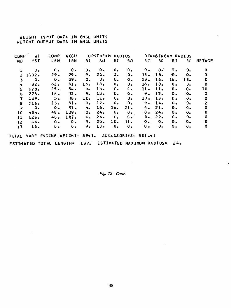
WEIGHT INPUT DATA IN ENGL UNITSWEIGHT OUTPUT DATA IN ENGL UNITS
COMP WTNO
1i3<*56789
10111213
£ST
0.1132.
0.32.
678.275..139.516.
0.<*#<».626.44.16.
COMPLfcN
0.29.0.
62.25.Id.5.
13.0.
48.48.0.0.
A CCULEN
0.29.29.91.54.72.78.91.91.
139.187.
0.0.
U P S T R E A M RADIUSRl
0.9.0.
16.9.9.
10.9.4.0.C.9.9.
KG
0.20.0.
18.13.13.11.12.16.24.24.20.13.
RI
0.0.0.0.C.0.0.0.
16.0.C.
10.0.
RO
0.0.0.0.C.0.0.0.
21.0.C.
11.0.
DOWNSTREAM RADIUSR I
0.13.13.16.11.9.
10.9.4.0.0.0.0.
RO
0.18.16.18.11.13.13.14.21.24.22.0.0.
RI
0.'0.16.0.0.0.0.0.0.0.0.0.0.
RO
0.0.
18.0.0.0.0.0.0.0.0.0.0.
NSTAGE
0300
1002200000
TOTAL BARE ENGINE WEIGHT= 3941. ACCtSSORIES= 301.41
ESTIMATED TOTAL LENGTH= 187. ESTIMATED MAXIMUM RADIUS' 24.
Fig. 12 Com.
38

AAAAA A A A ) A A A A A A A A A A A A A A A A A A A « A A A A N N N))
Cc CCCCCCCCCCCCtCC KPPPPPPPP T T T T T T T T T )t uCL-cwCCCCCC C CCCCLCLLCLPPPPHlV TfTTIT T I_CC CCCOCCC PPHPPPP T T T T T T T T T T T )
c/L C/L C/L C/L -C/L C/L C/L C/L )/L C/L C./L C/L L/L -C/L C/L
72. Cont.

UPUAlEo INPUf O A T A TO KEf-LtCI CALCULATED INPUT
NO. lireI INLtl
.. o-MP«L.>x.1 S f L l l l t K•* OU d ^: Loflp^LjKU UJLl J
/ T o k o T J tJ lOKiilNE•» M lA t<<
U JUCI bili NoZ-iLt»<: ShAM
1M»H
C A S t lOLNf l l -
UA[ 1NP1
0.^38500 03o.iuoGoj 010.773000 00C.OI .i30oOu 010.100030 Ov0.400OOO 01
O.^booo j ol0 . / O J 7 J O 030 .boO uOLi-010 • 4 /<: bbu C iO.tOOOOLi Oto.oOOCOJ O4
U\ UNK^
0.00. 0
C . O0.0
0.26LOOU-U 10.00. lOOooJ Jlo.O0.0392 bo J3O.oC. lOCC Oo 01G. lOOoOo Jl0. lO oCOo o 1
OATINP30.146960 020.4i -oOuO C4C.OC.O0.5 14350 04
C . C0.4<,7330 00o.j!.'5'77j GO3.i.-tOOOU ci0.0O.I.
O.lV.OOlr 01
O.iCOOou 01
OAT1NP4C.O0.37olOD 04C.OC.CC.3707CU 04(.26SOfb 04C. 380100 34C.3bo30D 04C.O0.00.0f . iniiooj 3 1O.lOoOOJ 01
JATINP50.?0.265900 030.00.00.614190 02C . 9 4 C C C ' u 0(0.7o6450 000.72633D OCo.O3. J CO 000 000.98oOOP 000.1DOOOO Cl0.100000 01
DATINP60.90000D 000.376200 04C.O0.00.37080D 04C.lb3C.fO Ci.0.3b020D 040.300400 040.0C.163003 05O. lOCCOo 01C. 1CCCCD Clo.icoooo 01
UATINP7O.C0.101130o.tiC.O0.9090900.0C.9C727D0.9401200.0O.C0.0C.I CO 000O.I DO 000
01
00
OSoo
Cl01
uATINPBC.O0.37630D L4O.CC.O0.370900 04O.u0.9C24*u CC0.815560 00G.O0.0O.Cr. 1C COCO Cl0.1COOOC 01
UATINP9o.r0.9922200.00.00.132460O.U0.1CCOOL.O. lOOOCuO.U0.0O.ICOOOOc.iroccoC .ICC 000
ro
01
Cl01
010101
ILAFUN SIMPLE Mu_tL
STATIL .N PRCIPEKIY OUTPUT O A T A
r-L 0*STA 1 UN
1<:*»
^o1bV
1C1 ili1314
1 ;
W c l o H TrLCM
STA IP1u.«.3tOOD 03C.23oX>tJ 03O.J3o50D 030.13475J 030.iJi»4u 033.350J40 010.13405u 030.13756U OJ0.1371>bO 03G.lo37iu 03o.^nl31J 030.241310 030.241310 030.103750 C3
T U T A LP KE bSU.it
ST AIP<:C. InlS^bU 0<:
o. i J 226u 020.3 /d_ jo 0^0.37b2bo O2C. J>ba 10 o jC. 355510 o30. 32 022 o 03( • bb j t Oo o 2l".3ou-»9o 020.37U2BO o2o. 37401o J^O. j515/o 320. 3bl57o •JtC. j7b2Bu I' 2
IOTALT E M P E R A fUKE
S T A T P 3o . b l f t S f o CoO.L>ld67L 030.7/:o370 C30.720870 03j. 143560 04
C. 143560 C4O.^f.5000 04J.ii-27bo 04C. 1/JlbL 040.726d7J 030. ijlS /D 040. 131570 C4O.i3157u 04C. 7,6670 OJ
FUEL/AIRRAT 13
S T A T P 4C.C0.0C.O0.0O.CC.o0.214250-010.208080-01C.2C868D-Cil0.00.11 79 OD —0 1C. 1 1 79 Oj —0 10.117900-01O.C
REFERRED(=L3W
S I A T P 5C . 2 3 8 5 C O 030.26499o 03C.1C9690 C30.6197CO 020.901830 010.00.139060 020.462760 020.948C10 02O.t7717i) 02O.lSlolJ 030.160650 030.160650 030.477170 02
MACHNUMaf-KS T A T P 6
0.0O.CC.C0.0C.OC.O0.0C.OC . 2 4 C C C O C C0.0C.Oo.iooooo Jl0.117290 ClC. 127340 oO
S T A T I CPRESSURE
S T A T P 7C .C0.0G.O0.00.0C.OC .0o.OC.374C100.0C.OC.18780D0.146960C. 374010
INTERFACE C D K K t C T E O
C2
020202
FLCJW ERROkSIATPb
O.o0.00.0C.O0.0C.OC.O0.0C.O0.00.00.0
C.Co.c
COMPONENT OUTPUT UATA
No'. TV PC* INLtl2 LoMHKLbKj Si>LmcH4 DUCT 3i oJMfKtbkt> OUC1 B/ lURdlNb0 TunolNty MlAEr t
lo ouCT 3
»! NjZtLtI.. SHAH
1 j inAF i
a *.„. o..
Alk r 1.0* |L3/
D A T O u r i0.0
-0.1b912U Ca0.7700OO UO0.0
-\J. 339 090 03
0.00.3 39 o9o Ou0.169 12 U C5u.70< <30 03O.U
0.13705J 050.0
C.O
ALI 1 I UUt
oAIJUli0.0
C.iCir oo 04C.C0.0C.boowoo 040. 10010U iO
C.40L' v.u C40.b39L5o 03o.60GOOO-ol0. 133790 04C. 400000 04
c.ccr ,Co ( s
l .«TOUT3O.oO.o3.o0.0o.G0.0
C . iCGGGG 01C.lu3«7U 010.0O.i392it> 310.4<y'OuO 04
r .c f ' ct j f4
UAIOUT4C.lOOOOo 31C.18000D 01C.O0.00.130000 010.21425U-31C 'lOOOGJ Ul0.250uOD 010.101140 010.00.483933 03C.40000J 34
C.bl.t COO 04
J AT OUT 50.100000 Cl0.400000 040.00.00.514550 040 .0
0.335770 OO0.472740 030.00.472830 030.0
0.3
DATOUT6O.C0.100000 01C.C0.00.985000 000.1C1230 05C 56ROOO OA0.524400 040.167730 C30.00.100000 010.0
C.O
OATOUT70.900000C. 265 900C .00.0C.0141UO0.00 7 06^5 00.726330C.O0.30.9800003.0
„.-
0003
02
nnUO00
00
DATOUT6O.ICOOOO 010.870000 00c.oC.OO.b70000 COO.V40000 CO& 6 b GOOD 00o.aboooo ooC. 94 99 00-160.00.187210 010.0
C.O
OATOUT9o.c0.28600Co .00.00.94060C
0.2650000.3 70 730O.L22340C.louOoDO.C0 .2392.30O.C
» .P
01
0104010101
01
= o. n tCJVHY= i;.-«COn 0 l l tKAT l - JN i ^ PAi iL^
jLo 1 -JII.3J OKL5S TrlhOiT 13Vd'.."l F O b L hLJU (Ln/HKl lil<rt . t!Nc 1
l . . iT-LLco IrtKJiT
JS.olL.C Tu lAL J ^ < A ^ L SHAFT
JNi( AL Li 0 T S t - C
<; . '/ 34 3 N t T 1 nK o S T / « 1 K f L 'JW
i.C D o A f l A l L oKAL-C..734? SPlLLAGr « LIP ORSC
w • CU I
Figure 12 Cont.

6.0 PROGRAM DIAGNOSTICS
The WATE-1 program contains error printout to aid the user in trouble shooting an input deck. A
listing of the error messages and their meanings are shown in Table 5. None of these errors will
cause termination of the program. The component routine in which the error occurred will be
terminated and the program will continue its calculations. The components calculated after an
error may or may not be in error.
Table 5. Error Messages
1. "Compressor, I, pressure ratio is too high" - more than 20
compressor stages calculated. First stage maximum pressure
ratio too small.
2. "Compressor, I. stage and blade parameters, meaningless" -
stage inlet Mach number less than or equal to zero, or hub
radius of compressor equals zero.
3. "Duct is not converging - error only called for rotating
splitter fan component. Inlet or exit Mach numbers of fan
may be input incorrectly.
4. "Error in shaft" - iteration for shaft diameter not converging.
Check shaft inputs.
5. "Turbine, I, work or radius too high, RC = , X.XX" - more
than 9 turbine stages calculated - turbine loading parameter
too small or control radius improperly input.
6. "Turbine, I, stage and blade parameters meaningless" - Mach
number or hub radius less than or equal to zero.
41
REFERENCES
1. Fishbach, L. H. and Caddy, M. J., "NNEP - The Navy-NASA Engine Program," NASA TM
X-71857, Dec. 1975.
42