A metallographic study of the path of fatigue failure in ...
38
H I LL INO I UNIVERSITY OF ILLINOIS AT URBANA-CHAMPAIGN PRODUCTION NOTE University of Illinois at Urbana-Champaign Library Large-scale Digitization Project, 2007.
Transcript of A metallographic study of the path of fatigue failure in ...

HI LL INO IUNIVERSITY OF ILLINOIS AT URBANA-CHAMPAIGN
PRODUCTION NOTE
University of Illinois atUrbana-Champaign Library
Large-scale Digitization Project, 2007.

UNIVERSITY OF -ILLINOIS BULLETINISSUED WEEKLY
Vol. XXV May 15, 1928 No. 37
[Entered as second-class matter December 11, 1912. at the post office at Urbana, Illinois, underthe Act of August 24, 1912. Acceptance for mailing at the special rate of postage provided
for in section 1103, Act of October 3, 1917, authorized July 31, 1918.]
A METALLOGRAPHIC STUDY OF THEPATH OF FATIGUE FAILURE
IN COPPER
BY
HERBERT F. MOORE
AND
FRANK C. HOWARD
BULLETIN No. 176ENGINEERING EXPERIMENT STATION
Peust#uaw at cn UzxvIaT m or IUINoIS, UiAsNA
Paics: TwmNr CarNts

T THE Engineering Experiment Station was -established byact of the Board of Trustees of the University of Illinoison December 8, 1903. It is the purpose of the Station to
conduct investigations and make studies of importance to theengineering, manufacturing, railway, mining, and other industrialinterests of the State.
The management of the Engineering Experiment Station isvested in an Executive Staff composed of the Director and hisAssistant, the Heads of the several Departments in the Collegeof Engineering, and the Professor of Industrial Chemistry. This-Staff is responsible for the establishment of general policies gov-erning the work of the Station, including the approval-of-materialfor publication. All members of the teaching staff of the Collegeare encouraged to engage in scientific research, either directly orin cooiperation with the Research Corps composed of full-timeresearch assistants, research graduate assistants, and specialinvestigators.
To render the results of its scientific investigations availableto the public, the Engineering Experiment Station publishes anddistributes a series of bulletins. Occasionally it publishes circu-lars of timely interest, presenting informationý of importance,compiled from various sources which may not readily be acces-sible to the clientele of the Station.
The volume and number at the top of the front cover pageare merely arbitrary numbers and refer to the general publica-tions of the University. Either above the title or below the sealis given the number of the Engineering Experiment Station bul-letin or circular which should be used in referring to these pub-lications....
For copies of bulletins or circulars or for other informationaddress
THE ENGINEERING ExaPEIMENT STATION,UNiv srrt or Ilu'VoTS,
URRANA, ILLIOIS

UNIVERSITY OF ILLINOIS
ENGINEERING EXPERIMENT STATION
BULLETIN No. 176 MAY, 1928
A METALLOGRAPHIC STUDY OF THE PATH
OF FATIGUE FAILURE IN COPPER
BY
HERBERT F. MOORERESEARCH PROFESSOR OF ENGINEERING MATERIALS
AND
FRANK C. HOWARDINSTRUCTOR IN CHEMISTRY
ENGINEERING EXPERIMENT STATIONPUBLISHED BY THE UNIVERSITY OF ILLINOIS, URBANA

q

CONTENTSPAGE
I. INTRODUCTION . . . . . . 5
1. Introductory . . . . . . . . . . . . 5
2. Acknowledgments . . . . . . . . . 5
II. METALLOGRAPHIC STUDY OF FATIGUE FAILURE IN COPPER 5
3. Previous Metallographic Studies of Fatigue Cracks 5
4. Material Studied . . . . . . . . 6
5. Apparatus and Specimens for Developing FatigueCrack . . . . . . . . . . . . 7
6. Procedure in Etching Specimens . . . . . . 7
7. Procedure in Developing a Fatigue Crack . . . 9
8. Structure of Specimens Before Being Subjected toRepeated Stress . . . . . . .. 9
9. Structure of Copper in the Vicinity of a FatigueCrack . . . . . . . . . . . . 16
III. CONCLUSIONS . . . . 16
10. Cone1ii~inn~........................................10. Conclusions . . . . . . .

LIST OF FIGURESNO. PAGE1. Specimen Used in Repeated-stress Tests ... . . . . . . . 72. Macrograph of Fatigue Cracks in Cold-drawn Copper Specimen . . . . 83. Testing Machine Used for Repeated-stress Tests . . . . . .. . 84. Micrograph of Drawn and Annealed Copper . . .. . . . . . 95. Micrograph of Cold-drawn Copper, Longitudinal Section . . . . . . 106. Micrograph of Cold-drawn Copper, Transverse Section . . . . . . 117a. High-magnification Micrograph of Annealed Copper-Mottled . . . . 127b. High-magnification Micrograph of Annealed Copper-Herring-bone 138. Micrograph of Cast Copper . . . . . .. . . . . . . . 149. Micrographs of Cast Copper . . . . . . . . . . . . . . 15
10. Micrograph of Fatigue Crack in Rolled and Annealed Copper . . . . . 1811. Micrograph of Fatigue Crack in Cold-drawn Copper . . . . . . . 1912. Micrograph of Fatigue Crack in Cold-drawn Copper, Repolished after De-
velopment of Crack .... . . . . . . . . . . 1913. Micrograph of Fatigue Crack in Cast Copper . . . . . . . . . 2014. Micrograph of Disturbance Lines Around Fatigue Crack in Cold-drawn
Copper . . .. . . . . . . . . . . . . . . . . 2115. Micrographs of Disturbance Lines Around and Ahead of Fatigue Cracks in
Cold-drawn Copper . . . . . . . . . . . . . . 22
16. Micrograph of Surface Disturbance Lines Showing Possible Formation ofFatigue Crack in Cold-drawn Copper . . . . . . . . . . 23
17. Micrograph of Disturbance Lines Ahead of a Fatigue Crack in Rolled andAnnealed Copper ..... . . . . . . . . . . 24
18. Micrograph of Fatigue Crack in Cold-drawn Copper . . . . . . . 2519. Micrograph of Fatigue Crack in Cold-drawn Copper . . . . . . . 26
20. Micrograph of Fatigue Crack in Cast Copper . . . . . . . . . 27
A METALLOGRAPHIC STUDY OF THE
PATH OF FATIGUE FAILURE IN COPPER
I. INTRODUCTION
1. Introductory.-The study of the failure of metals under re-peated stress, commonly known as "fatigue" of metals, has usuallybeen carried on by means of mechanical tests of strength. It has,however, become evident that a study of the nature and mechanismof the progressive fracture which seems to constitute fatigue failuremay well employ metallographic examination as an aid in explainingthe beginning and the progress of a fatigue fracture. This bulletinrecords such a study of progressive fracture in copper.
2. Acknowledgments.-Most of the micrographs shown in thisbulletin were taken by Mr. K. L. Schanbacher in connection with hisbachelor's thesis in chemical engineering, and the writers wish tomake a very special acknowledgment to him for his diligence andcare in that work.
This study has been carried on as a part of the work of theEngineering Experiment Station of the University of Illinois, and hasbeen under the general administrative direction of Dean M. S. Ket-chum, director of the Engineering Experiment Station, and of Profes-sor D. B. Keyes, head of the Division of Applied Chemistry, and Pro-fessor M. L. Enger, head of the Department of Theoretical and Ap-plied Mechanics.
II. METALLOGRAPHIC STUDY OF FATIGUE FAILURE IN COPPER
3. Previous Metallographic Studies of Fatigue Cracks.-Variousinvestigators have taken micrographs of fatigue cracks and Mr. F. F.Lucas, Metallurgist of the Bell Telephone Laboratories, New York,has made a very careful study of the path of fatigue failure in Armcoiron.*
In his investigation of the path of fatigue failure, with magnifi-cations ranging from 100 to 4800, he found that in the case of Armcoiron:
"1. Non-metallic inclusions in Armco iron are a potential source ofweakness when such metal is subjected to reversed cycles of stress.
*Lucas, F. F., "Observations on the Microstructure of the Path of Fatigue Failure in aSpecimen of Armco Iron," Trans. Am. Soc. for Steel Treating, April, 1927.
6 ILLINOIS ENGINEERING EXPERIMENT STATION
"2. Iron carbide when occurring as inclusions in Armco iron is not asource of weakness.
"3. Non-metallic inclusions seem to be insecurely seated in the metaland the boundary between the inclusion and the metal is the path oftenfollowed by the fatigue crack.
"4. The non-metallic inclusions act as 'stepping-stones' for the fatiguecrack.
"5. Grain boundaries do not appear to be a potential source of weak-ness.
"6. Reversed cycles of stress appear to produce disturbances in thestructure of the metal in advance of the visible crack, as disclosed by lightetching. This condition at times can be disclosed by deeper etching.
"7. Disturbances in the metal structure adjoining the path of fatiguefailure seem to be highly localized to the immediate neighborhood of thecrack.
"8. Slip planes, strain lines, Neumann bands or other similar markingswere not found if the strained condition of the metal immediately adjoin-ing the crack is disregarded."
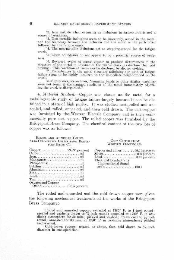
4. Material Studied.-Copper was chosen as the metal for ametallographic study of fatigue failure largely because it can be ob-tained in a state of high purity. It was studied cast, rolled and an-nealed, and rolled, annealed, and then cold drawn. The cast copperwas furnished by the Western Electric Company and is their com-mercially pure cast copper. The rolled copper was furnished by theBridgeport Brass Company. The chemical content of the two lots ofcopper was as follows:
ROLLED AND ANNEALED COPPERALSO COLD-DRAWN COPPER FROM BRIDGE- CAST COPPER FROM
PORT BRASS CO. WESTERN ELECTRIC CO.
Copper.................99.895 per cent Copper and Silver........ 99.91 per centCarbon ......................... . nil Silver .................... . 0.006 per centIron........................... nil Lead.................... 0.01 per centManganese...................... nil Electrical ConductivityPhosphorus.....................nil (International Stand-Sulphur................. .... . nil ard) ................... 100.1Aluminum ...................... nilZinc............................ nilLead........................... nilT in ............................ nilOxygen and Copper
Oxide................ 0.105 per cent
The rolled and annealed and the cold-drawn copper were giventhe following mechanical treatments at the works of the BridgeportBrass Company:
Rolled and annealed copper: extruded at 13800 F. to 1 inch round;pickled and washed; drawn to 7/ inch round; annealed at 1290° F. in oxi-dizing atmosphere for 30 min.; pickled and washed; drawn cold to % inchround; annealed for 30 min. at 1290° F. in oxidizing atmosphere; pickledand washed.
Cold-drawn copper: treated as above, then cold drawn to 1 inchdiameter in one operation.

THE PATH OF FATIGUE FAILURE IN COPPER
FIG. 1. SPECIMEN USED IN REPEATED-STRESS TESTS
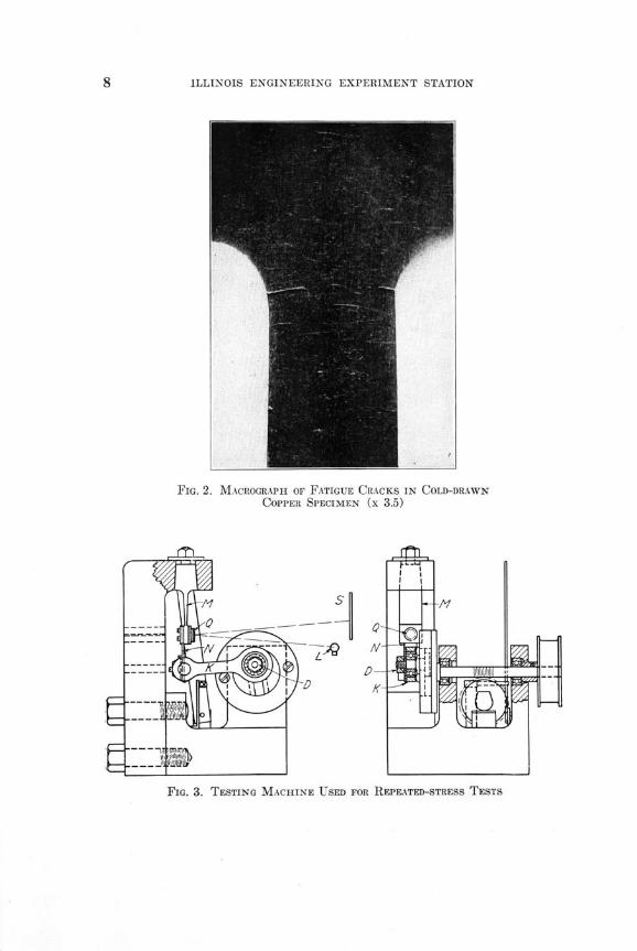
5. Apparatus and Specimens for Developing Fatigue Crack.-Thetest specimens in which fatigue cracks were developed are shown inFig. 1. The specimen was clamped at its upper end. and the lower endwas bent back and forth in a plane perpendicular to the plane of thepaper. The points of maximum bending stress were at the junctionof fillet (%-inch radius) and the narrower part of the specimen. Fig-ure 2 shows a specimen with a fatigue crack in it. Figure 3 showsthe testing machine used to subject the specimen to cycles of re-peated stress. The specimen N is fastened at one end to the calibratedspring M and the other end is vibrated back and forth by the con-necting rod K, which is operated by the variable-throw crank D. Ifthe throw of the crank D is increased, the bending moment is in-creased, and the deflection of Q, a concave mirror attached to thecalibrated spring, is increased, causing a motion of the ray of lightreflected from the lamp L to the screen S. The image of a filament ofthe lamp is focussed at S. The length of the band of light, reflectedon the screen S as the machine runs, is a measure of the bendingmoment, and hence of the range of flexural stress in the specimen. Acounter is provided to measure the number of cycles of stress applied.
6. Procedure in Etching Specimens.-Each specimen studied waspolished over the surfaces near the fillets, using Nos. 1 to 0000 emerypaper and, finally, jeweler's rouge. Various etching solutions weretried to bring out the microstructure of the copper. Some etching
8 ILLINOIS ENGINEERING EXPERIMENT STATION
FIG. 2. MACROGRAPH OF FATIGUE CRACKS IN COLD-DRAWN
COPPER SPECIMEN (x 3.5)
FIG. 3. TESTING MACHINE USED FOR REPEATED-STRESS TESTS
THE PATH OF FATIGUE FAILURE IN COPPER
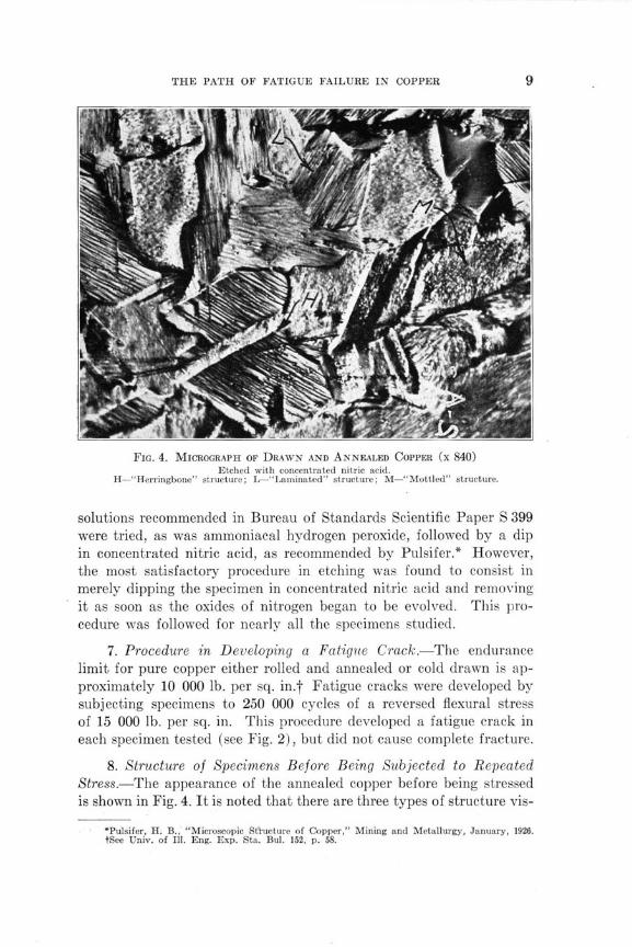
FIG. 4. MICROGRAPH OF DRAWN AND ANNEALED COPPER (x 840)Etched with concentrated nitric acid.
H-"Herringbone" structure; L-"Laminated" structure; M-"Mottled" structure.
solutions recommended in Bureau of Standards Scientific Paper S 399were tried, as was ammoniacal hydrogen peroxide, followed by a dipin concentrated nitric acid, as recommended by Pulsifer.* However,the most satisfactory procedure in etching was found to consist inmerely dipping the specimen in concentrated nitric acid and removingit as soon as the oxides of nitrogen began to be evolved. This pro-cedure was followed for nearly all the specimens studied.
7. Procedure in Developing a Fatigue Crack.-The endurancelimit for pure copper either rolled and annealed or cold drawn is ap-proximately 10 000 lb. per sq. in.t Fatigue cracks were developed bysubjecting specimens to 250 000 cycles of a reversed flexural stressof 15 000 lb. per sq. in. This procedure developed a fatigue crack ineach specimen tested (see Fig. 2), but did not cause complete fracture.
8. Structure of Specimens Before Being Subjected to RepeatedStress.-The appearance of the annealed copper before being stressedis shown in Fig. 4. It is noted that there are three types of structure vis-
*Pulsifer, H. B., "Microscopic StYucture of Copper," Mining and Metallurgy, January, 1926.tSee Univ. of Ill. Eng. Exp. Sta. Bul. 152, p. 58.
ILLINOIS ENGINEERING EXPERIMENT STATION
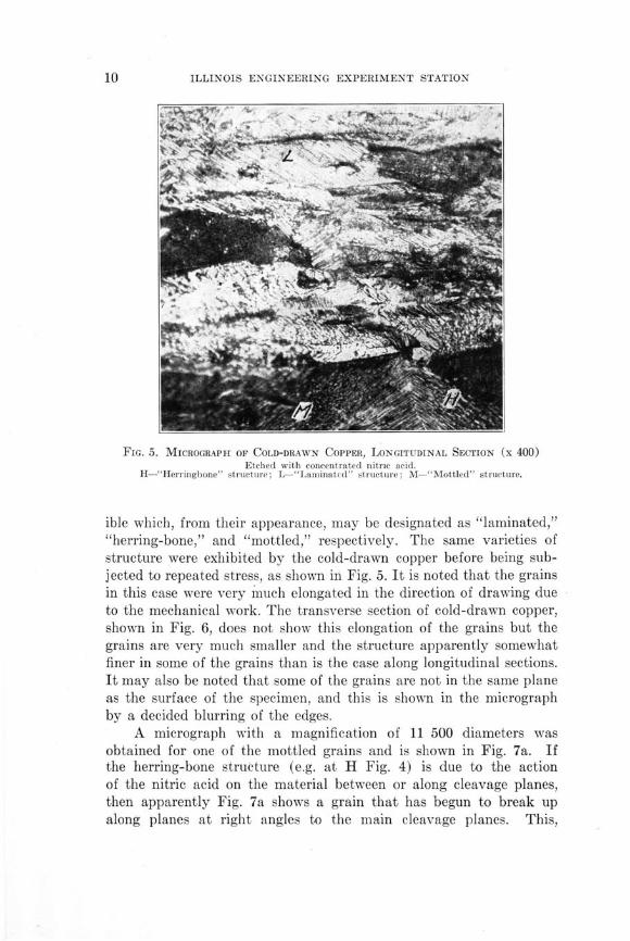
FIG. 5. MICROGRAPH OF COLD-DRAWN COPPER, LONGITUDINAL SECTION (x 400)Etched with concentrated nitric acid.
H-"Herringbone" structure; L-"Laminated" structure; M-"Mottled" structure.
ible which, from their appearance, may be designated as "laminated,""herring-bone," and "mottled," respectively. The same varieties ofstructure were exhibited by the cold-drawn copper before being sub-jected to repeated stress, as shown in Fig. 5. It is noted that the grainsin this case were very much elongated in the direction of drawing dueto the mechanical work. The transverse section of cold-drawn copper,shown in Fig. 6, does not show this elongation of the grains but thegrains are very much smaller and the structure apparently somewhatfiner in some of the grains than is the case along longitudinal sections.It may also be noted that some of the grains are not in the same planeas the surface of the specimen, and this is shown in the micrographby a decided blurring of the edges.
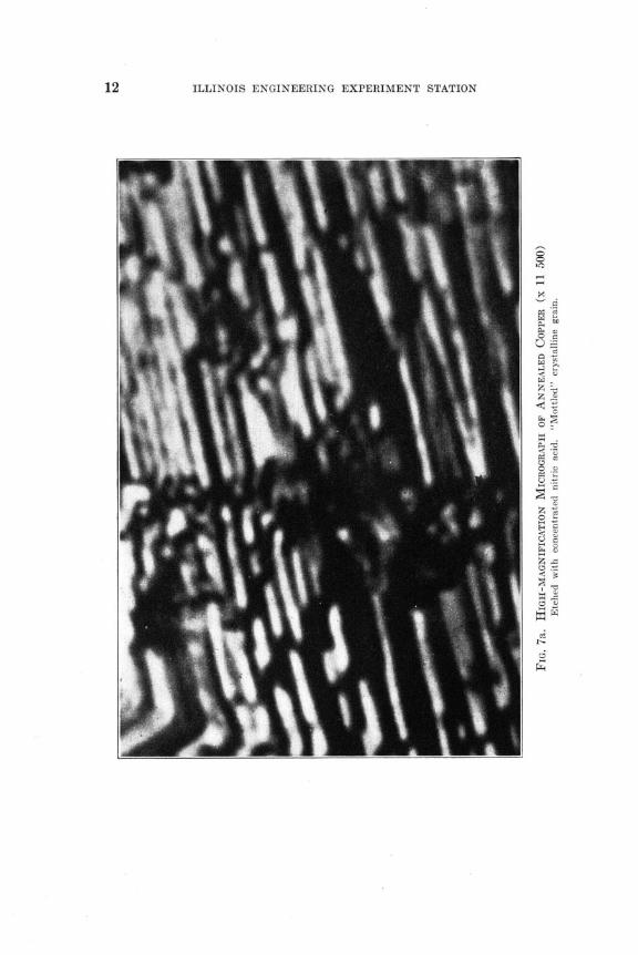
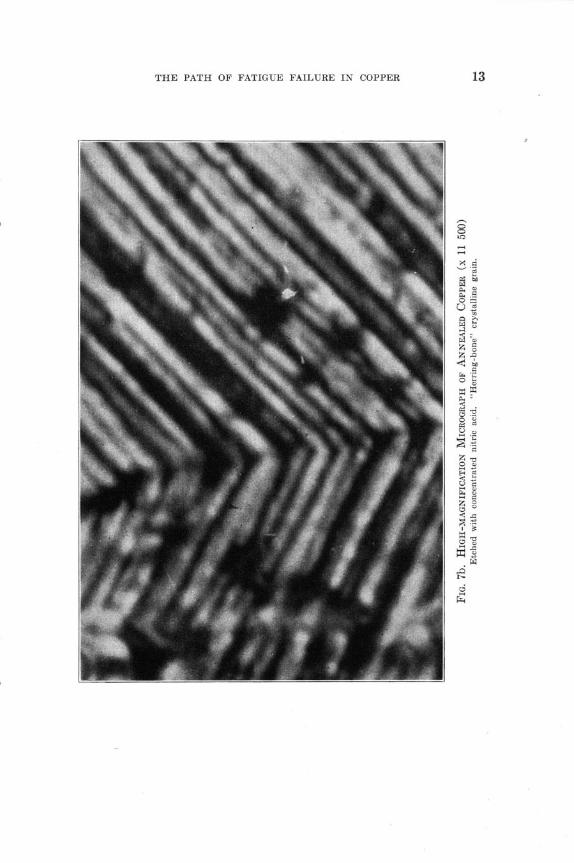
A micrograph with a magnification of 11 500 diameters wasobtained for one of the mottled grains and is shown in Fig. 7a. Ifthe herring-bone structure (e.g. at H Fig. 4) is due to the actionof the nitric acid on the material between or along cleavage planes,then apparently Fig. 7a shows a grain that has begun to break upalong planes at right angles to the main cleavage planes. This,

THE PATH OF FATIGUE FAILURE IN COPPER
~W> ~
FIG. 6. MICROGRAPH OF COLD-DRAWN COPPER, TRANSVERSE SECTION (x 1300)Etched with concentrated nitric acid.
therefore, would seem to indicate not only that there is a set of second-ary cleavage planes at right angles to the primary cleavage planesbut also that in this particular case the annealing not only failedto remove the evidences of strain within the crystal but also failed to"heal" a grain that had started to disrupt.
The distance between the laminated or parallel lines in the micro-graphs (Figs. 4, 7, 18, and 19) can be measured and then the corre-sponding distance in the specimen can be calculated. It was foundthat this distance varied from 0.0004 to 0.001 millimeters. These dis-tances are well within the theoretical resolving power of the objectivesused. The theoretical resolving power is the smallest distance that
may be resolved optically; or d = 2a where X = the wave length of
light used in mm., a - numerical aperture, d = the smallest resolvabledistance in mm. A Bausch and Lomb green filter was used in thiswork so that X = 0.00053 mm.; for the oil immersion objective a = 1.3,
ILLINOIS ENGINEERING EXPERIMENT STATION
THE PATH OF FATIGUE FAILURE IN COPPER
z 5Q ,
0 s
S

ILLINOIS ENGINEERING EXPERIMENT STATION
FIG. 8. MICROGRAPH OF CAST COPPER (X 800)Etched with concentrated nitric acid.
0.00053therefore d .00053 0.0002 mm.
2 X 1.3Figure 8 shows the structure of a piece of the same copper as
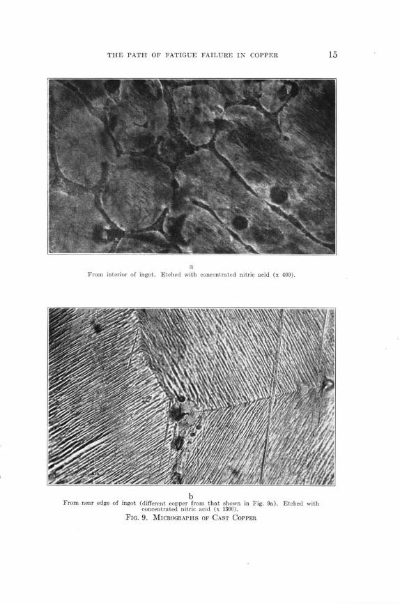
shown in Figs. 4 and 5 after being remelted and cast into a mold. Thelaminated and herring-bone structures seem to be absent in this case;however, in Fig. 9 are shown micrographs of cast copper supplied bythe Western Electric Company. The specimen 9b was taken fromnear the edge of the ingot. The appearance of the micrograph suggestsa very fine laminated structure within the grain. Figure 8 shows amicrograph of cast copper taken from the interior of an ingot; noevidence of laminated structure is shown, and this was typical of allspecimens of cast copper or cast alloys of copper (other than thatshown in Fig. 9b) which have been examined by the writers.
THE PATH OF FATIGUE FAILURE IN COPPER
aFrom interior of ingot. Etched with concentrated nitric acid (x 400).
bFrom near edge of ingot (different copper from that shown in Fig. 9a). Etched with
concentrated nitric acid (x 1300).
FIG. 9. MICROGRAPHS OF CAST COPPER

ILLINOIS ENGINEERING EXPERIMENT STATION
FIG. 10. MICROGRAPH OF FATIGUE CRACK IN ROLLED AND ANNEALED COPPER (X 100)
Unetched.
The laminated structures, herring-bone structures, and, perhaps,the mottled structure found in the unstressed copper seem to showplanes within crystalline grains which are particularly susceptible tochemical attack. Whether these planes are also indicators of struc-tural weakness is an interesting question on which a little light isthrown by the results of the repeated stress tests. It would be veryinteresting to find out whether these planes that are susceptible tochemical attack bear any relation to the characteristic planes of thespace lattice of copper, but the writers have no data to offer on thatquestion.
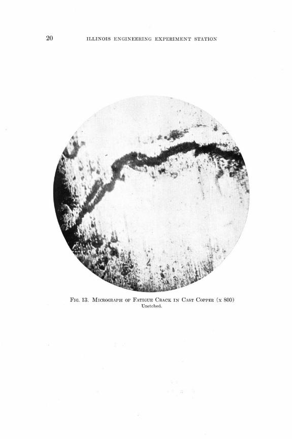
9. Structure of Copper in the Vicinity of a Fatigue Crack.-Figures10, 11, 12, and 13 are micrographs of unetched specimens taken so asto show a fatigue crack developed as described on page 9. Figure 10is a micrograph of annealed drawn copper; Fig. 11 is a micrographof cold-drawn copper; Fig. 12 is a micrograph of cold-drawn copperrepolished after the development of the fatigue crack; and Fig. 13 is amicrograph of cast copper from the Western Electric Co.
Lucas in his study of fatigue cracks in Armco iron reported a"disturbed region" round the crack. Figures 10 and 11 show such a
THE PATH OF FATIGUE FAILURE IN COPPER
disturbed region very plainly for the drawn and annealed, and thecold-drawn copper. Figure 12 is interesting as showing that the evi-dences of the disturbed area are removed by repolishing. Figure 13,showing a fatigue crack in cast copper, gives little evidence of a dis-turbed region around the crack. This is in accord with the evidenceshown by micrographs of copper etched after the development of afatigue crack.
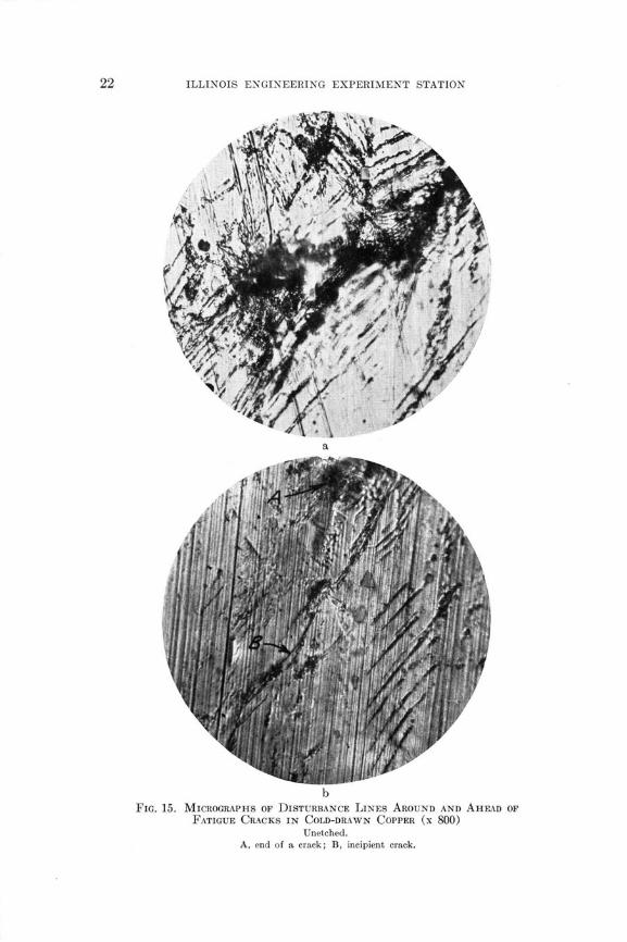
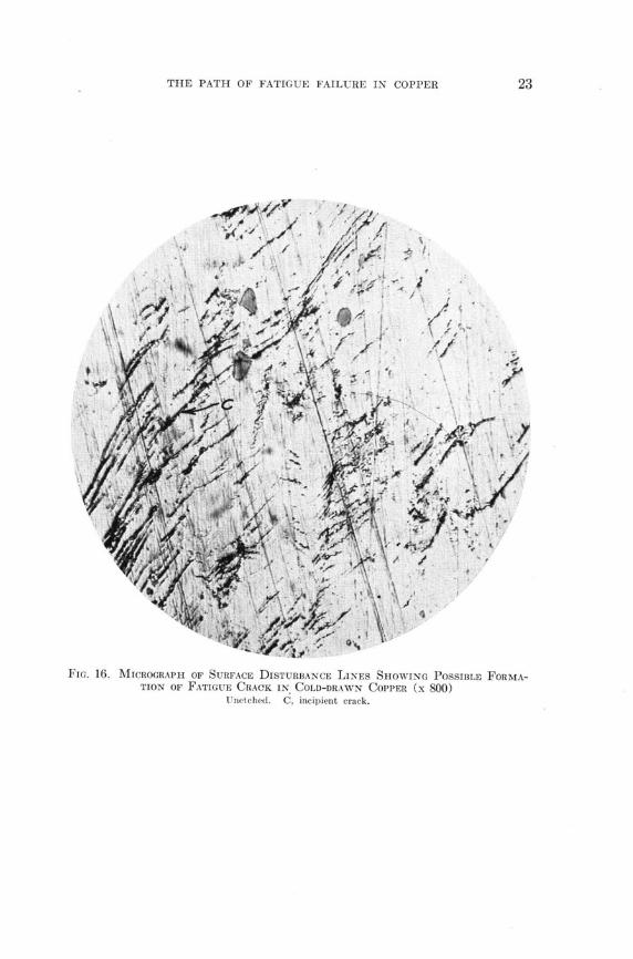
In Figs. 14 and 15 a general tendency towards parallelism be-tween crack and disturbance lines is noted, while Figs. 15 and 16show disturbance lines apparently acting as advance agents for theprogress of the crack. Figure 17 shows disturbance lines in drawn andannealed copper.
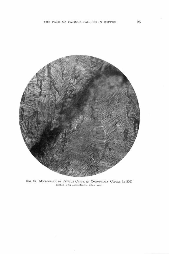
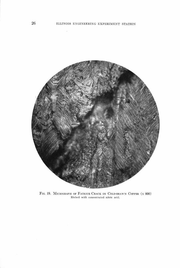
Figures 18 and 19 are micrographs showing the appearance ofcold-drawn copper in the vicinity of a fatigue crack after the surfaceof the metal had been etched with concentrated nitric acid. Thedisturbed region around the crack is less clearly marked than was thecase for the unetched surfaces shown in Figs. 10 to 17, inclusive, andis shown as an out-of-focus blurred region at the edge of the crack.The crystalline structure of the copper is similar to that shown inFig. 5, and no change in that structure is apparent. In certain placesthere seems to be a tendency for the crack to follow a path parallelto the laminae of the grains, but at other places the crack goes acrossthese laminae.
To the writers a study of Figs. 10 to 18, inclusive, suggests thefollowing picture of the origin and spread of a fatigue crack in copper:The crack originates in surface disturbances such as are shown inFigs. 15 and 16. Once the crack is started it spreads inwards and alsoalong the surface, the major factor governing its spread being thestress concentration at its edges, and a minor factor being local planesof weakness in different crystalline grains. The copper tested wasalmost free of inclusions; in Fig. 16 the incipient crack C is seen pass-ing at the edge of an inclusion, as was frequently found by Lucas in hisstudy of Armco iron. In general, however, the inclusions are so few,except possibly in the case of cast copper, and so widely scattered thatthey do not affect the path of the crack in the copper specimensstudied.
III. CONCLUSIONS
10. Conclusions.-As a result of the investigation the followingconclusions are given:
ILLINOIS ENGINEERING EXPERIMENT STATION
(1) By etching with concentrated nitric acid there wasbrought out in the rolled copper tested an intra-granular struc-ture consisting of laminae separated by planes especially sensitiveto chemical attack. This structure was brought out in one speci-men of cast copper tested.
(2) Specimens of rolled copper, subjected to repeated flexureuntil a fatigue crack developed, showed a surface disturbance ofthe metal in the vicinity of the crack. This surface disturbanceseems analogous to that found by Lucas in Armco iron, but ismuch more clearly marked in the case of rolled cold-drawncopper.
(3) The surface disturbance is shown in micrographs of un-etched specimens by lines. The crack as it forms tends to extendparallel to these lines, and the lines seem to develop ahead of thecrack, and in the direction which the crack follows as it progresses.Polishing the surface of a specimen removed or covered up alltraces of this disturbance.
(4) The rolled copper tested had in it so few inclusions thatany tendency of the crack to take a course from inclusion to in-clusion was not in evidence.
(5) Specimens of rolled copper etched after the developmentof a fatigue crack showed no evidence of any change in crystallinestructure, and after the surface had been eaten away by theetching reagent the disturbed region in the vicinity of the crackwas much less in evidence than on the unetched surface.

THE PATH OF FATIGUE FAILURE IN COPPER 19
FIG. 11. MICROGRAPH OF FATIGUE CRACK IN COLD-DRAWN COPPER (x 100)Unetched.
FIG. 12. MICROGRAPH OF FATIGUE CRACK IN COLD-DRAWN COPPER, REPOLISHED AFTERDEVELOPMENT OF CRACK (X 100)
ILLINOIS ENGINEERING EXPERIMENT STATION
FIG. 13. MICROGRAPH OF FATIGUE CRACK IN CAST COPPER (x 800)Unetched.
,Ný, -11:ý

THE PATH OF FATIGUE FAILURE IN COPPER
FIG. 14. MICROGRAPH OF DISTURBANCE LINES AROUND FATIGUE CRACK
IN COLD-DRAWN COPPER (X 800)
Unetched.
ILLINOIS ENGINEERING EXPERIMENT STATION
bFIG. 15. MICROGRAPHS OF DISTURBANCE LINES AROUND AND AHEAD OF
FATIGUE CRACKS IN COLD-DRAWN COPPER (X 800)
Unetched.A, end of a crack; B, incipient crack.
THE PATH OF FATIGUE FAILURE IN COPPER
FIG. 16. MICROGRAPH OF SURFACE DISTURBANCE LINES SHOWING POSSIBLE FORMA-TION OF FATIGUE CRACK IN COLD-DRAWN COPPER (X 800)
Unetched. C, incipient crack.

ILLINOIS ENGINEERING EXPERIMENT STATION
FIG. 17. MICROGRAPH OF DISTURBANCE LINES AHEAD OF A FATIGUE CRACKIN ROLLED AND ANNEALED COPPER (X 800)
End of crack not in field of view. Unetched.
THE PATH OF FATIGUE FAILURE IN COPPER
FIG. 18. MICROGRAPH OF FATIGUE CRACK IN COLD-DRAWN COPPER (X 800)Etched with concentrated nitric acid.
ILLINOIS ENGINEERING EXPERIMENT STATION
FIG. 19. MICROGRAPH OF FATIGUE CRACK IN COLD-DRAWN COPPER (x 800)Etched with concentrated nitric acid.
THE PATH OF FATIGUE FAILURE IN COPPER
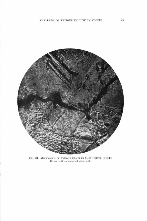
FIG. 20. MICROGRAPH OF FATIGUE CRACK IN CAST COPPER (x 800)
Etched with concentrated nitric acid.

RECENT PUBLICATIONS OFTHE ENGINEERING EXPERIMENT STATIONt
Bulletin No. 115. The Relation between the Elastic Strengths of Steel inTension, Compression, and Shear, by F. B. Seely and W. J. Putnam. 1920. Twentycents.
Bulletin No.116. Bituminous Coal Storage Practice, by H. H. Stoek, C. W.Hippard, and W. D. Langtry. 1920. None available.
Bulletin No. 117. Emissivity of Heat from Various Surfaces, by V. S. Day,1920. Twenty cents.
Bulletin No.118. Dissolved Gases in Glass, by E. W. Washburn, F. F.Footitt, and E. N. Bunting. 1920. Twenty cents.
*Bulletin No. 119. Some Conditions Affecting the Usefulness of Iron Oxidefor City Gas Purification, by W. A. Dunkley. 1921. Thirty-five cents.
Circular No. 9. The Functions of the Engineering Experiment Station ofthe University of Illinois, by C. R. Richards. 1921.
Bulletin No. 120. Investigation of Warm-Air Furnaces and Heating Systems,by A. C. Willard, A. P. Kratz, and V. S. Day. 1921. Seventy-five cents.
Bulletin No. 121. The Volute in Architecture and Architectural Decoration,by Rexford Newcomb. 1921. Forty-five cents.
Bulletin No. 122. The Thermal Conductivity and Diffusivity of Concrete, byA. P. Carman and R. A. Nelson. 1921. Twenty cents.
Bulletin No. 123. Studies on Cooling of Fresh Concrete in Freezing Weather,by Tokujiro Yoshida. 1921. Thirty cents.
Bulletin No. 124. An Investigation of the Fatigue of Metals, by H. F. Mooreand J. B. Kommers. 1921. Ninety-five cents.
Bulletin No. 125. The Distribution of the Forms of Sulphur in the Coal Bed,by H. F. Yancey and Thomas Fraser. 1921. Fifty cents.
Bulletin No. 126. A Study of the Effect of Moisture Content upon the Ex-pansion and Contraction of Plain and Reinforced Concrete, by T. Matsumoto.1921. Twenty cents.
Bulletin No. 127. Sound-Proof Partitions, by F. R. Watson. 1922. Forty-five cents.
Bulletin No. 128. The Ignition Temperature of Coal, by R. W. Arms. 1922.Thirty-five cents.
Bulletin No.129. An Investigation of the Properties of Chilled Iron CarWheels. Part I. Wheel Fit and Static Load Strains, by J. M. Snodgrass andF. H. Guldner. 1922. Fifty-five cents.
Bulletin No. 130. The Reheating of Compressed Air, by C. R. Richards andJ. N. Vedder. 1922. Fifty cents.
Bulletin No.181. A Study of Air-Steam Mixtures, by L. A. Wilson withC. R. Richards. 1922. Seventy-five cents.
Bulletin No. 132. A Study of Coal Mine Haulage in Illinois, by H. H. Stoek,J. R. Fleming, and A. J. Hoskin. 1922. Seventy cents.
Bulletin No. 133. A Study of Explosions of Gaseous Mixtures, by A. P.Kratz and C. Z. Rosecrans. 1922. Fifty-five cents.
Bulletin No. 184. An Investigation of the Properties of Chilled Iron CarWheels. Part II. Wheel Fit, Static Load, and Flange Pressure Strains. UltimateStrength of Flange, by J. M. Snodgrass and F. H. Guldner. 1922. Forty cents.
tOnly a partial list of the publications of the Engineering Experiment Station is publishedin this bulletin. For a complete list of the publications as far as Bulletin No. 134, see thatbulletin or the publications previous to it. Copies of the complete list of publications can be ob-tained without charge by addressing the Engineering Experiment Station, Urbana, Ill.
*A limited number of copies of bulletins starred are available for free distribution.
ILLINOIS ENGINEERING EXPERIMENT STATION
Circular No. 10. The Grading of Earth Roads, by Wilbur M. Wilson. 1923.Fifteen cents.
Bulletin No. 135. An Investigation of the Properties of Chilled Iron CarWheels. Part III. Strains Due to Brake Application. Coefficient of Friction andBrake-Shoe Wear, by J. M. Snodgrass and F. H. Guldner. 1923. Fifty cents.
Bulletin No. 136. An Investigation of the Fatigue of Metals. Series of1922, by H. F. Moore and T. M. Jasper. 1923. Fifty cents.
Bulletin No. 137. The Strength of Concrete; its Relation to the Cement,Aggregates, and Water, by A. N. Talbot and F. E. Richart. 1923. Sixty cents.
Bulletin No. 138. Alkali-Vapor Detector Tubes, by Hugh A. Brown andChas. T. Knipp. 1923. Twenty cents.
Bulletin No. 139. An Investigation of the Maximum Temperatures and Pres-sures Attainable in the Combustion of Gaseous and Liquid Fuels, by G. A. Good-enough and G. T. Felbeck. 1923. Eighty cents.
Bulletin No. 140. Viscosities and Surface Tensions of the Soda-Lime-SilicaGlasses at High Temperatures, by E. W. Washburn, G. R. Shelton, and E. E.Libman. 1924. Forty-five cents.
Bulletin No. 141. Investigation of Warm-Air Furnaces and Heating Sys-tems. Part II, by A. C. Willard, A. P. Kratz, and V. S. Day. 1924. Eighty-fivecents.
Bulletin No. 142. Investigation of the Fatigue of Metals; Series of 1923, byH. F. Moore and T. M. Jasper. 1924. Forty-five cents.
Circular No. 11. The Oiling of Earth Roads, by Wilbur M. Wilson. 1924.Fifteen cents.
Bulletin No. 143. Tests on the Hydraulics and Pneumatics of House Plumb-ing, by H. E. Babbitt. 1924. Forty cents.
Bulletin No. 144. Power Studies in Illinois Coal Mining, by A. J. Hoskinand Thomas Fraser. 1924. Forty-five cents.
Circular No. 12. The Analysis of Fuel Gas, by S. W. Parr and F. E. Vanda-veer. 1925. Twenty cents.
Bulletin No. 145. Non-Carrier Radio Telephone Transmission, by H. A.Brown and C. A. Keener. 1925. Fifteen cents.
Bulletin No. 146. Total and Partial Vapor Pressures of Aqueous AmmoniaSolutions, by T. A. Wilson. 1925. Twenty-five cents.
Bulletin No. 147. Investigation of Antennae by Means of Models, by J. T.Tykociner. 1925. Thirty-five cents.
Bulletin No. 148. Radio Telephone Modulation, by H. A. Brown and C. A.Keener. 1925. Thirty cents.
Bulletin No. 149. An Investigation of the Efficiency and Durability of SpurGears, by C. W. Ham and J. W. Huckert. 1925. Fifty cents.
Bulletin No. 150. A Thermodynamic Analysis of Gas Engine Tests, by C. Z.Rosecrans and G. T. Felbeck. 1925. Fifty cents.
Bulletin No. 151. A Study of Skip Hoisting at Illinois Coal Mines, by ArthurJ. Hoskin. 1925. Thirty-five cents.
Bulletin No. 152. Investigation of the Fatigue of Metals; Series of 1925, byH. F. Moore and T. M. Jasper. 1925. Fifty cents.
*Bulletin No. 153. The Effect of Temperature on the Registration of SinglePhase Induction Watthour Meters, by A. R. Knight and M. A. Faucett. 1926.Fifteen cents.
*Bulletin No. 154. An Investigation of the Translucency of Porcelains, byC. W. Parmelee and P. W. Ketchum. 1926. Fifteen cents.
Bulletin No. 155. The Cause and Prevention of Embrittlement of BoilerPlate, by S. W. Parr and F. G. Straub. 1926. Thirty-five cents.

THE PATH OF FATIGUE FAILURE IN COPPER
Bulletin No. 156. Tests of the Fatigue Strength of Cast Steel, by H. F.Moore. 1926. Ten cents.
*Bulletin No.157. An Investigation of the Mechanism of Explosive Reac-tions, by C. Z. Rosecrans. 1926. Thirty-five cents.
*Circular No. 13. The Density of Carbon Dioxide with a Table of Recalcu-lated Values, by S. W. Parr and W. R. King, Jr. 1926. Fifteen cents.
*Circular No. 14. The Measurement of the Permeability of Ceramic Bodies,by P. W. Ketchum, A. E. R. Westman, and R. K. Hursh. 1926. Fifteen cents.
*Bulletin No.158. The Measurement of Air Quantities and Energy Losses inMine Entries, by A. C. Callen and C. M. Smith. 1926. Forty-five cents.
*Bulletin No.159. An Investigation of Twist Drills. Part II, by B. W. Bene-dict and A. E. Hershey. 1926. Forty cents.
*Bulletin No. 160. A Thermodynamic Analysis of Internal Combustion EngineCycles, by G. A. Goodenough and J. B. Baker. 1927. Forty cents.
*Bulletin No.161. Short Wave Transmitters and Methods of Tuning, byJ. T. Tykociner. 1927. Thirty-five cents.
Bulletin No. 162. Tests on the Bearing Value of Large Rollers, by W. M.Wilson. 1927. Forty cents.
*Bulletin No.163. A Study of Hard Finish Gypsum Plasters, by Thomas N.McVay. 1927. Twenty-five cents.
Bulletin No. 164. Tests of the Fatigue Strength of Cast Iron, by H. F.Moore, S. W. Lyon, and N. P. Inglis. 1927. Thirty cents.
Bulletin No. 165. A Study of Fatigue Cracks in Car Axles, by H. F. Moore.1927. Fifteen cents.
BulletinNo. 166. Investigation of Web Stresses in Reinforced ConcreteBeams, by F. E. Richart. 1927. Sixty cents.
*Bulletin No. 167. Freight Train Curve-Resistance on a One-Degree Curveand a Three-Degree Curve, by Edward C. Schmidt. 1927. Twenty-five cents.
*Bulletin No.168. Heat Transmission Through Boiler Tubes, by Huber 0.Croft. 1927. Thirty cents.
*Bulletin No. 169. Effect of Enclosures on Direct Steam Radiator Perform-ance, by Maurice K. Fahnestock. 1927. Twenty cents.
*Bulletin No. 170. The Measurement of Air Quantities and Energy Losses inMine Entries. Part II, by Alfred C. Callen and Cloyde M. Smith. 1927. Forty-five cents.
*Bulletin No. 171. Heat Transfer in Ammonia Condensers, by Alonzo P.Kratz, Horace J. Macintire, and Richard E. Gould. 1927. Thirty-five cents.
*Bulletin No. 172. The Absorption of Sound by Materials, by Floyd R. Wat-son. 1927. Twenty cents.
*Bulletin No. 173. The Surface Tension of Molten Metals, by Earl E. Lib-man. 1928. Thirty cents.
*Circular No. 16. A Simple Method of Determining Stress in Curved Flex-ural Members, by Benjamin J. Wilson and John F. Quereau. 1928. Fifteen cents.
*BulletinNo.174. The Effect of Climatic Changes upon a Multiple-SpanReinforced Concrete Arch Bridge, by Wilbur M. Wilson. 1928. Forty cents.
*Bulletin No.175. An Investigation of Web Stresses in Reinforced ConcreteBeams. Part II. Restrained Beams, by Frank E. Richart, and Louis J. Larson.1928. Forty-five cents.
*Bulletin No. 176. A Metallographic Study of the Path of Fatigue Failurein Copper, by Herbert F. Moore and Frank C. Howard. 1928. Twenty cents.

THE UNIVERSITY OF ILLINOISTHE STATE UNIVERSITY
UrbanaDAVID KI•IEY, Ph.D., LL.D., President
THE UNIVERSITY INCLUDES THE FOLLOWING DEPARTMENTS:
The Graduate School
The College of Liberal Arts and Sciences (Curricula: General with majors, inthe Humanities and the Sciences; Chemistry and Chemical Engineering;Pre-legal, Pre-medical, and Pre-dental; Pre-journalism, Home Economics,Economic Entomology, and Applied Optics)
The College of Commerce and Business Administration (Curricula: GeneralBusiness, Banking and Finance, Insurance, Accountancy, Railway Adminis-tration, Railway Transportation, Industrial Administration, Foreign Com-merce, Commercial Teachers, Trade and Civic Secretarial Service, PublicUtilities, Commerce and Law)
The College of Engineering (Curricula: Architecture, Ceramics; Architectural,Ceramic, Civil, Electrical, Gas, General, Mechanical, Mining, and RailwayEngineering; Engineering Physics)
The College of Agriculture (Curricula: General Agriculture; Floriculture; HomeEconomics; Landscape Architecture; Smith-Hughes--in conjunction with theCollege of Education)
The College of Education (Curricula: Two year, prescribing junior standing foradmission-General Education, Smith-Hughes Agriculture, Smith-HughesHome Economics, Public School Music; Four year, admitting from the highschool-Industrial Education, Athletic Coaching, Physical Education
The University High School is the practice school of the College ofEducation)
The School of Music (four-year curriculum)
The College of Law (three-year curriculum based on two years of college work.For requirements after January 1, 1929 address the Registrar)
The Library School (two-year curriculum for college graduates)
The School of Journalism (two-year curriculum based on two years of collegework)
The College of Medicine (in Chicago)
The College of Dentistry (in Chicago)
The School of Pharmacy (in Chicago)
The Summer Session (eight weeks)
Experiment Stationa and Scieutific Bureaus:E U. . Agricultural ExperimentStation; Engineering Experiment Station; State Natural History Survey;State Water Survey; State Geological Survey; Bureau of EducationalResearch.
The Libray collections contain (June 1, 1926) 711,743 volumes and 155,331pamphlets.
For catalogs and information address•S- THE REGISTRAR
.Urbana, Illinois

'I.** &
¼. ..
- x
^/ J