A Me Co Portal Scraper Reclaimer
38
NP 01 TEC TECHNOLOGIES stacker • reclaimer • shiplaoder • systems worldwide © Ameco • AgileBusiness™
-
Upload
adityapathak -
Category
Documents
-
view
185 -
download
13
description
Portal Scraper and Reclaimer for Fertlizer Plants by Ameco
Transcript of A Me Co Portal Scraper Reclaimer

NP
01
R
TEC
TEC
HN
OLO
GIE
S
R
s t a c k e r • r e c l a i m e r • s h i p l a o d e r • s y s t e m s w o r l d w i d e
© A
mec
o • A
gile
Busi
ness
™

NP
02

NP
03
AMECO offer a full line of Stackers, Reclaimers, and Blending Systems for handling all kind of bulk materials such as fertilizers, sulphur, wood chips and bark, limestone and clay, soy meal, coal, cement, clinker, ores, etc... AMECO has references throughout the world in the Chemical and Petro-Chemical Industries, Mining Industry, Pulp and Paper Industry, Cement Industry, Power Generation and Co-Generation Plants, Ports and Harbour facilities.
The highly perfoming team of specialists - more than 25 years of experience, and equiped with amazing sophisticated «state of art» automated design tools - is at your disposal for designing, specifying and supplying a bulk handling system for your particular needs.
Enter in the history of AMECO and make your succesful business.
Stephane KillianChairman of the Board
AMECO’S headquaters, Illfurth - France

NP
04
P O R T A L S C R A P E R B Y A M E C OThe portal scraper is normally used in a production line as bulk material buffer store.
The store operates with stockpiles placed in line. While building up one pile, another pile is being reclaimed. Being the historically
main product of AMECO since 1932, we have a strong knowledge in this system and our machines are handling a broad range
of bulk materials, eg. woodchips, urea, ammonium nitrates, coal, gypsum, iron ores...
The input material comes on a rubber-belt conveyor and is
discharged through the stacker traveling on rails alongside
the store at a constant speed. Its height above the top of the
pile is kept at a minimum distance to reduce dust emission.
Alternatively, stacking can take place by using a tripper car
supported by a frame structure above the pile.
The stacker and the portal scraper travel on separate rails
along the store.
The portal scraper reclaimer is moving alongside the pile
to be reclaimed onto two tracks supported on concrete
foundations and located at each side of the pile.
The reclaiming is accomplished by one or several luffing
scraper arm(s) long enough to reach across the pile.
The arms are made of a boom equipped with chains and
blades for dragging the material to a belt conveyor.

NP
05
Boom
Boom
Electrical feed for power and controls is
accomplished by use of multicomposition
cable and motor cable reel.
The machine may be operated locally using controls located
on operating console inside the cabin or from a remote location.
The two scraper arms are linked together at a knee joint. The secondary
arm lifts the material to the top of the pile, feeding the primary arm.

NP
06
S I D E S C R A P E R S T O R E B Y A M E C OThe side scraper is used in a production line as small bulk material buffer store.The store operates with stockpiles placed in line. While building up one pile, another pile is being reclaimed. The store can be circular or longitudinal.
The input material comes on a rubber-belt conveyor and is discharged through the stacker traveling on rails alongside the store. Its height above the top of the pile is kept at a minimum distance to reduce dust emission.
Alternatively, stacking can take place by using a tripper car supported by a frame structure above the pile.The stacker and the portal scraper travel on separate rails along the store.The side scraper reclaims the material by means of a scraper chain which removes material from the pile, thanks to a
scraper arm long enough to reach across the pile.The arm is made of a boom equipped with chains and blades for dragging the material to a belt conveyor.

NP
07
General performance of AMECO equipment
Max. capacity built : 2500m3/h – 1200TPH to 3000TPH
Max span built : 63.5m – 65m
Being one of the historically main product of AMECO since 1932, we have
a strong knowledge in this system and this type of machine is mainly
handling woodchips.

NP
08H O M O G E N E I Z I N G S T A C K E R - R E C L A I M E R S S Y S T E M S
PrEHOMOGENISATION
A prehomogenising store is often
necesary when the chemical
composition of raw material varies
greatly (e.g limestone, clay or coal).
The most common stacking
methods are chevron, windrow and
cone shell. These methods consist of
stacking a large number of layers on
top of each other in the direction of
the pile.
1 . LO N G I T u d I N A L H O M O G E N I z I N G S TA C k E r - r E C L A I M E r S y S T E M
The longitudinal stacker-reclaimer system operates
with two piles. One pile is stacked while the other is
being reclaimed.
The input material comes on a rubber-belt conveyor
and is discharged through the stacker traveling
on rails alongside the store at a constant speed. Its
height above the top of the pile is kept at a minimum
distance to reduce dust emission.
The reclaimer bridge moves alongside the pile onto
two rails located on each side of the pile.
reclaiming takes place from the face of the pile to be reclaimed by a
harrow travelling on the bridge reclaimer. The sweeping movements
of the harrow cause the material to slide on the pile base.
A scraper conveyor equipped with chains and blades drags the
material to a belt conveyor located along the pile, and the material
goes to the next process step.
Electrical feed for power and controls is accomplished by use of
multicomposition cable and motor cable reel.
The machine may be operated locally using controls located on
operating console inside the cabin or from a remote location.
CounterweightStation boom

NP
09
2 . C I r C u L A r H O M O G E N I z I N G S TA C k E r - r E C L A I M E r S y S T E M
Boom
Boom
The circular homogenizing stacker-reclaimer system is staking material in one ring shaped pile. The stacker is located on the centre column, allowing rotation in both directions. Its height above the top of the pile is kept at a minimum distance to reduce dust emission.
The reclaimer bridge rotates around the central column.
Like the longitudinal reclaimer bridge, reclaiming takes place from the face of the pile to be reclaimed by a harrow traveling on the bridge reclaimer. The sweeping movements of the harrow cause the material to slide on the pile base.A scraper conveyor equipped with chains and blades drags the material to a central hopper.In order to maximize the storage capacity, the homogenised material leaves the store by an underground conveyor.

NP
010
MISSION IMPOSSIBLE SuCCESSFuLin operation 6 months A.R.O.
Early January, the client called a meeting in Longyearbyen to discuss the possibility of installing a new port facility near the Svea coal mine, in Sptizbergen. After two days of travelling we arrived in a land of complete darkness.
A good layer of snow was on the runway and the pilots explained us that they were very much used to this type of situations. Coming out of the plane was uneasy, as a bitter cold wind was greeting our arrival with large tick flakes. Due to a decision of the client, we were not asked to go to the mine area as no one was sure that we would be able to make it back due to bad weather conditions. The meetings took then place in the client’s offices in Longyearbyen.
During the first discussions with the client it became apparent that very strict delivery dates would be required in order to comply with the stringent weatherconditions of the area and the fact that it was of the utmost necessity that the coal being produced be exported during the same year. Normally such machines are delivered FOB port of export in a time frame of eleven to thirteen month there is to be added travelling timeon the ship, unloading and erection which could is such area be as much as two and a half month.
In this case the client made it clear that he wished that the machine with the complete conveyor belt installation should be commissioned by July 15th, as the first ship could be loading coal at such date.
We then inquired about the possibilities coalat such date. We then inquired about the possibilities of crane hiring in the area and were informed that the largest one would be a 25 ton crane.
Furthermore, the client did not have a suitable existing jetty and that such will have to be constructed to allow shiploader erection.
We decided then that due to all these conditions that the only possible solution would be to erect and test the machine somewhere at a port and load it onto a ship or a barge to bring it in due time to the site thus leaving sufficient time for a partial jetty construction long enough to accommodate the shiploader in the beginning
MISSION IMPOSSIBLE STARTS
On January 21 the agreement was signed and then Mission Impossible started.Due to all client and weather constraints, the machine had to be redesigned practically from scratch. The long lead items purchase orders were placed within the month of January, and the structural manufacturer was selected right away, not on price but on delivery capabilities. Thedrawings were fed to the structural shop as soon as they became available.
Of course, the client had waived its right to comment on the drawings, but this was even more bearing on us since the site conditions had never been dealt with by our engineers.
Mid of April, the client visited the structural manufacturing shop and saw already many large structures being completed. Although the battle was not won yet, he was somewhat reassured that we were in the right direction. The port of Gdansk was chosen for erecting the machine on the grounds that the structural steel shop was Polish, and that the port of Gdansk is on the North Sea.
The erection took two month but mostly due to the fact that importing goods into Poland is not so easy and requires much time and efforts.
THE VOYAGE TO THE POLE
When finally the ship arrived several days after originally planned, it wasa brand new ship who made
NP
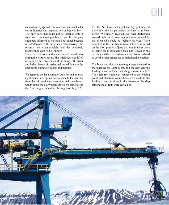
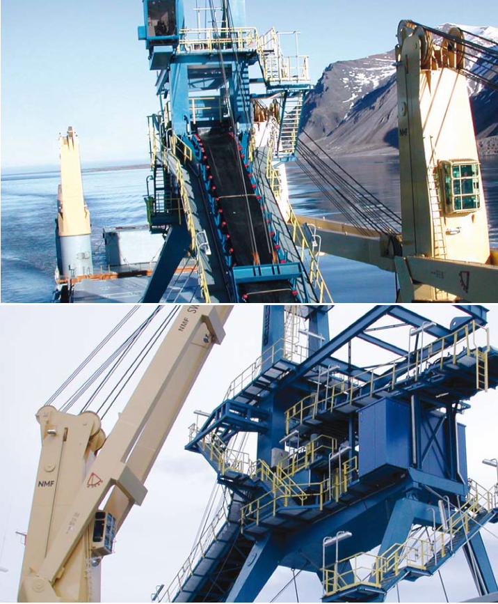
011to 13th. No it was not night but daylight since at these times there is permanent daylight in the Polar Circle. We finally reached our final destination around eight in the morning and were greeted by the client who could not believe his eyes. Three days before the rail tracks were not even installed on the short portion of jetty that was in the process of being built. Unloading took until seven in the evening and then we had twenty four hours on hand to use the ships cranes for completing the erection.
The brace and the counterweight were attached to the machine the same night, and the next day the loading spout and the belt slinger were attached. The cable reel cable was connected to the feeding point and electrical connections were made to the loading spout. At three in the afternoon, the ship left and small tests were carried on.
its maiden voyage with our machine, our shiploader was fully tested and inspected everything was fine. The only parts that could not be installed onto it were one counterweight brace that the shipping engineers informed us we should not attach because of interference with the cranes manoeuvring, the seventy tons counterweight and the telescopic loading tube with its belt slinger. These last items could create unsafe conditions during the journey at sea. The shiploader was lifted on deck by the own cranes of the heavy-lift carrier and lashed heavylift carrier and lashed down to the deck using numerous cables and manilas.
We departed on the evening of July 9th and after an eight hours interruption due to some bolts shearing from the ship engine exhaust pipe, and some heavy winds along the Norwegian shores we came to see the Spitzbergen Island in the night of July 12th

NP
012
AMECO’S shiploarder loaded, in the Van Mijen Fjord

NP
013
On July 8th, the shiploader was already tested and completely erected except for the counterweight box and loading chute with belt slinger, as well as one of the counterweight braces all these items that could endanger the safety of the journey at sea while sailing to the Spitzbergen Island final destination Svea.
The ship arrived late afternoon and the loading took the major portion of the night, and lashing, another twelve hours.On our journey to final destination, we had to cross under the new bridge connecting Sweden to Denmark. The bridge is only 55 meter above sea level and optically it looked as we were not going to clear the bottom of the bridge. A rapid calculation shiploader height about 35 meters plus ships height unknown but estimated at least 15 meters above deck, prompted us to brace ourselves for the impact. Of course, the shipping agency had checked all this before and the Captain let his ship go at the full speed of 22 Knot to its encounter.
Finally we passed and pressure dropped. On our journey, after some hardship due to a failure of the bolts attaching the exhaust pipe to the main ship engine, and staying for eight hours on the anchor, we were blessed with force 7 and 8 winds along the Norwegian shores for a full day.On July 13th early morning, we have entered the Van Mijen Fjord and are sailing in between two rows of glaciers covered mountains.
Daylight is 24 hours in this zone at that time of year.
NP
014

NP
015
S h i p S i z e s m a x 61,000 dW T
S h i p S i z e s m i n 20 000 dW T
L o a d i n g r a t e 2000 t/h
P r o d u c t h a n d l e d Coal
P r o d u c t d e n s i t y 0 .85
P r o d u c t S i z e 50 mm
L o a d i n g d e v i c e Belt S l inger
r a i l c e n t e r d i s t a n c e 10 m
B o m m L e n g t h 27.5 m
S l u i n g A n g l e +/- 75°
T o t a l W e i g h t 230 t
T o t a l P o w e r i n s t 270 kW
T o t a l P o w e r u s e d 200 kW
Shiploader data
Maxi boom upper posit ion + 45 °
Maxi boom lower posit ion (at - 30°
Hoist ing speed at bai l 2 ,3 m/min
Number of cable 2
Cables diameter 28 mm
Motor ’s power 37 kW
Safety brake release power pack motor 2.2 kW
detail of hoisting drum and Safety brake
Belt Width 1600 mm
Belt speed 2 .45 m/sec
Troughing Angle 20°
C. to C . Pul leys 27.5 m
drive Power 75 kW
Belt Width 1400 mm
Belt speed 2 .95 m/sec
Troughing Angle 45°
C. to C . Pul leys 11 m
drive Power 45 kW
detail of boom belt drive pulleys
Feeder Belt details

NP
016
CIrCuLAr STACkEr rECLAIMEr SySTEMS by Ameco
An automated system allowing very large pile diameters and low profile bulding outlines tailored closely to the machine shape
These machines are designed around a central column solidly anchored to the ground via foundations or piling. The reclaimer is located at the lower portion of the system, and is composed of a portal structure with machinery room, made of heavy plates and sections, connected to the central column using a large diameter sluing ring without gear. The other side of the portal structure is fitted to a traveling truck with driven and idle wheels rolling on a crane rail of circular shape.Inside the machinery room, one hoisting drum using planetary gear reducer, allows to raise and lower the reclaimer arms.
At the lower portion of the machinery room structure, two smaller sluing rings connect the primary reclaiming boom to the machinery room allowing luffing movement of the boom, via a hoist drum and cable system located inside the machinery room. The upper hoist sheaves are installed inside the upper elbow element of the portal structure. Reclaiming is achieved by two beams connected together by sluing rings. These arms are fitted out with chains and blades for scraping the product from the pile and bringing it, via a chute located below the central column, to the reclaim conveyor installed in a tunnel below the store.
The chain devices are driven, via chain sprockets, by one, two or three spiral bevel gear reducers directly attached to the chain drive shafts. The chain required tension is achieved by using take-up screws fitted with bevel spring washers thus allowing enough elasticity to the take-up system to compensate for the chain jogging movement caused by the use of an eight tooth sprocket.
For some large machines, or upon customer’s request, this take-up device can be arranged using hydraulic cylinders and hydraulic power pack..This reclaimer type does not require the use of any counterweight unlike the CSS type machines. The reclaimer is equipped with an operator cabin housing the electrical switch gear and PLC cabinet for both the stacker and the reclaimer.
Electrical feed is achieved by bringing power and control cables through one of the legs of the central column into a box located inside the central column allowing cable chain feeding. A cable chain system or cable carts system is used for allowing a full 360° rotation to the reclaimer. This cable chain or cable carts system carries also the cables going from the motor control center and PLC cabinet to the stacker.
Should it be required for any reason whatsoever that the machines could be required to make several consecutive 360° rotations, it could be arranged using a collector ring inside of the central column. The cable chain system would then only limit the movement in between the stacker and the reclaimer to a maximum of 360°
The operator cabin houses also an operator interface terminal allowing full control and monitoring of the reclaimer and the stacker. Access to the reclaimer is arranged from the bottom level at the pile center by a stair and generously sized platforms. Another stairway is attached to the portal structure thus allowing also access from the road around the pile outskirt.

NP
017

NP
018

NP
019
The access to the sluing stacker is achieved using ladders to an intermediate platform and further ladders to reach the two walkways on the stacker boom.
The stacker is located at the top of the central column and could be designed to carry some of the incoming loads of the field feeder conveyor. A sluing support is attached to the top of the central column using a large diameter sluing ring with internal gear. If conveyor loads are to be accounted for then a second sluing ring will be placed on top of the sluing support thus allowing to have an incoming conveyor support that is independent from the stacker sluing.
The incoming conveyor can then be supported on this structure by using a roller system eliminating the horizontal loads due to the heat expansion and conveyor take-up loads. The sluing movement of the stacker is achieved using a planetary gear with spur gear pinion engaging directly to the sluing ring internal gear.
The stacker boom is attached to the sluing support via tow pillow blocks and a shaft. Depending on the size of the stacker and also upon client’s requirements, the luffing movement of this machine could be arranged using hoist winding drum and cable or hydraulic cylinders and power pack.
When hydraulic power pack and cylinders are used, the stacker counterweight is directly attached to the end of the luffing stacker boom for counterbalancing the boom overhang load and some of the product
load. When cable hoist is used, the counterweight does not counterbalance the boom directly but only the sluing support.The hoist boom is equipped with conveyor pulleys, troughing and return idlers, belt scrapers, chutes and skirt boards, end baffle plate, and more generally all components required to design a safe conveyor system.
The stacker is controlled from the operator cabin located on the reclaimer. It can build piles in two different manners either cone shell type piles (the best suited) or chevron piles upon request by the operator.
Platforms located on each side of the stacker boom give easy access to all conveyor components. Conveyor is covered with easily opened covers. The boom is luffing using a hoisting system designed with reeling drum, cable and sheaves. via hydraulic coupling, and directly mounted to the chain drive shaft.
The large bay windows allow clear sight of the reclaiming area. A split system air conditioner is keeping the temperature inside the cabin to comfortable levels. Both switch gears for stacker and reclaimer are located inside this room.
The cabin is hanging from the side of the reclaimer portal structure. Access to the cabin is arranged with a stairway from the floor level at the center of the pile. Further access is arranged from the walkway at the outskirt of the pile over the portal reclaimer structure. A floodlight is installed on top of the cabin to illuminate the working zone.

NP
020
CIrCuLAr STACkEr rECLAIMEr SySTEMS by Ameco
The moste economical automatic storage facility using a stacker reclaimer system in outdoors applications
These machines are designed around a central column solidly anchored to the ground via foundations or piling. The reclaimer is located at the lower portion of the system, and is composed of a machinery room made of heavy plates and sections, connected to the central column using a large diameter sluing ring with gear.Inside the machinery room, two planetary type sluing drive gear reducers engage their pinions extending through the bottom of the structure, onto the sluing ring gearing, which is fixed with respect to the central column, thus allowing the reclaimer sluing movement. At the lower portion of the machinery room structure, two smaller sluing rings connect the reclaiming boom to the machinery room allowing luffing movement of the boom, via a hoist drum and cable system located on top of the machinery room, and a hoisting boom attached to it. The reclaiming boom is fitted out with chains and blades for scraping the product from the pile and bringing it, via an elevating trough attached to the reclaimer machinery room, into a chute located around the lower portion of the central column.The chain device is driven, via chain sprockets, by one or two spiral bevel gear reducers directly attached to the chain drive shaft. The chain required tension is achieved by gravity using the catenary’s effect of the chain upper strand. A screw type take-up is used for positioning the take-up sprockets and adjusting the length of the catenaries. The reclaimer boom vertical load is equilibrated using large concrete counterweights placed onto the machinery
room tail portion, at the opposite side of the reclaimer arm connection. This counterweight is calculated to optimize the overhang load that is applied to the sluing ring.The reclaimer is equipped with a motor control center housing the electrical switch gear and PLC cabinet for both the stacker and the reclaimer. Electrical feed is achieved by bringing power and control cables through one of the legs of the central column into a box located inside the central column. A cable chain system is used for allowing a full 360° rotation to the reclaimer if so desired. This cable chain system carries also the cables going from the motor control center and PLC cabinet to the stacker. An operator cabin is located at an elevated level on the front of the machinery room. This cabin houses an operator interface terminal allowing full control and monitoring of the reclaimer and the stacker. Access to the reclaimer is arranged from the bottom level by a short ladder first to allow the reclaimer to come very close to the reclaim conveyor, and then by stairways and generously sized platforms. The top of the machinery room is receiving a circular platform giving access to the sluing stacker. The stacker is located at the top of the central column and could be designed to carry some of the incoming loads of the field feeder conveyor. A sluing support is attached to the top of the central column using a large diameter sluing ring with internal gear. If conveyor loads are to be accounted for then a second sluing ring will be placed on top of the

NP
021
CIrCuLAr STACkEr rECLAIMEr SySTEMS by Ameco

NP
022
sluing support thus allowing to have an incoming conveyor support that is independent from the stacker sluing. The incoming conveyor can then be supported on this structure by using a roller system eliminating the horizontal loads due to the heat expansion and conveyor take-up loads. The sluing movement of the stacker is achieved using a planetary gear
with spur gear pinion engaging directly to the sluing ring internal gear. The stacker boom is attached to the sluing support via tow pillow blocks and a shaft. Depending on the size of the stacker and also upon client’s requirements, the luffing movement of this machine could be arranged using hoist winding drum and cable or hydraulic cylinders and power pack. When hydraulic power pack and cylinders are used,
the stacker counterweight is directly attached to the end of the luffing stacker boom for counterbalancing the boom overhang load and some of the product load. When cable hoist is used, the counterweight does not counterbalance the boom directly but only the sluing support.The hoist boom is equipped with conveyor pulleys, troughing and return idlers, belt scrapers, chutes and skirt boards, end baffle
plate, and more generally all components required to design a safe conveyor system. The stacker is controlled from the operator cabin located on the reclaimer. It can build piles in two different manners either cone shell type piles (the best suited) or chevron piles upon request by the operator.

NP
023

NP
024
Our machines allows for large reclaiming and stacking capacities and rates, either for indoor or outdoor application. Full automatic operation, no operators needed. Highly accurate reclaiming rate with fine tunning and remote setting. Full self diagnostic with programmable controller and operator interface terminal.
All of your requirements will be adhered to, just inform us of your specific needs Ameco systems are designed to follow your specific requests.
“”

NP
025
NP
026

NP
027
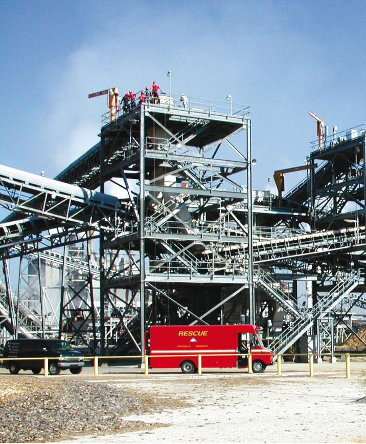
AMECO’S systems are designed for the greatest projects

NP
028
The shiploader is the last piece of equipement in the material handling system. The shiploader’s position, at the end of the product stream, must be failure free.
AMECO shiploader are available either for bulk handling, or bag handling, or bag and bulk depending on thre tool connected on the shiploader. In order to easily intechange the tools on the shiploader, a resting tower can be placed at one end of the jetty. The resting tower is designed to receive either the bulk loading spout, telescopic loading tube or the bag loading spiral chute.An operator cabin is located on the same level as the counterweight boom and is accessible by the platform looking towards the shiploader luffing boom. The top of the traveling bridge receive the conveyor system. Access is given to all maintenance points by way of stairs and ladders.
“”

NP
029

NP
030All stacking modes can be selected from the local operator interface terminal. Stacking modes are : chevron mode, windrow mode, axial mode or cone shell mode.
“
”

NP
031
Main drives such as belt, and hoist drives are designed with enclosed gears, eliminating the need for secondary gearing. Only the traveling and sluing movements are designed using secondary open gears such as spur gear ring on the powered wheels, spur gears on large diameter sluing rings for circular stackers.

NP
032

NP
033

NP
034
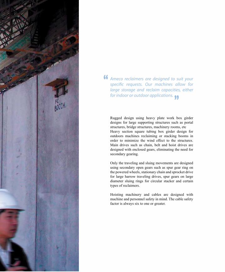
Rugged design using heavy plate work box girder designs for large supporting structures such as portal structures, bridge structures, machinery rooms, etcHeavy section square tubing box girder design for outdoors machines reclaiming or stacking booms in order to minimize the wind effect to the structures. Main drives such as chain, belt and hoist drives are designed with enclosed gears, eliminating the need for secondary gearing.
Only the traveling and sluing movements are designed using secondary open gears such as spur gear ring on the powered wheels, stationary chain and sprocket drive for large harrow traveling drives, spur gears on large diameter sluing rings for circular stacker and certain types of reclaimers.
Hoisting machinery and cables are designed with machine and personnel safety in mind. The cable safety factor is always six to one or greater.
Ameco reclaimers are designed to suit your specific requests. Our machines allow for large storage and reclaim capacities, either for indoor or outdoor applications.
“”

NP
036
uPdATE ANd HIGHTLIGHTS ONWWW.AMECO-Fr.COM

NP
037
© 2
008
Agi
leBu
sine
ss™
• P
hoto
s A
MEC
O S
.A
R
43, rue du 21 Novembre F-68720 ILLFURTHTél. : +33(0)3 89 25 59 69 Fax : +33(0)3 89 25 59 68
H E A D Q U AT E R S
AMECO N.A.4001A Wetherburn Way Norcross, GA 30092Tel. +1.770.797.2656Fax +1.770.797.2799
U S O F F I C E
R
Florent GERARDWuhan Economic and Technological Development ZoneHUBEI - CHINAPhone : +(86) 13147197147
AMECO SCORPIOBulk Handling Ltd«SCORPIO HOUSE», III Floor132, Wheeler Road, Cox TownBangalore - 560 005, INDIA.Phone 1 : +91 80 25484733
C H I N A O F F I C E
I N D I A O F F I C E