
A LSS-based registration of stereo thermal–visible videos of multiple people using belief...
12
A LSS-based registration of stereo thermal–visible videos of multiple people using belief propagation Atousa Torabi ⇑ , Guillaume-Alexandre Bilodeau LITIV, Department of Computer and Software Engineering, École Polytechnique de Montréal, P.O. Box 6079, Station Centre-ville, Montréal, Québec H3C 3A7, Canada article info Article history: Received 5 March 2012 Accepted 15 January 2013 Available online 12 July 2013 Keywords: IR camera Visible camera Dense stereo matching Belief propagation Local self-similarity Multimodal video registration abstract In this paper, we propose a novel stereo method for registering foreground objects in a pair of thermal and visible videos of close-range scenes. In our stereo matching, we use Local Self-Similarity (LSS) as similarity metric between thermal and visible images. In order to accurately assign disparities to depth discontinuities and occluded Region Of Interest (ROI), we have integrated color and motion cues as soft constraints in an energy minimization framework. The optimal disparity map is approximated for image ROIs using a Belief Propagation (BP) algorithm. We tested our registration method on several challenging close-range indoor video frames of multiple people at different depths, with different clothing, and different poses. We show that our global optimization algorithm significantly outperforms the existing state-of-the art method, especially for disparity assignment of occluded people at different depth in close-range surveillance scenes and for relatively large camera baseline. Ó 2013 Elsevier Inc. All rights reserved. 1. Introduction In the recent years, by reduction in the price of infrared sensors, there has been a growing interest in visual surveillance using ther- mal–visible imaging system for civilian applications. The advanta- ges of jointly using a thermal camera with a visible camera have been discussed comprehensively in [1–4]. Combining visible and infrared information allows to better handling shadow, reflection, noise, misdetection, and missing information. The combined data enables better detection and tracking of people. Moreover, for hu- man activity analysis, the joint use of thermal and visible data en- ables us to better detect and segment the regions related to the object that people may carry based on their temperature differ- ences compared to the human body. A fundamental issue associated to data fusion of close-range thermal–visible imaging is accurately registering corresponding information and features of images with dramatic visual differ- ences. For a close-range scene, matching corresponding features in a pair of visible and thermal videos is much more difficult than for a long-range scene. People might be in very different sizes due to their distances to the camera, in different poses, and at different levels of occlusion. They might have colorful/textured clothes that are visible in color images, but not in thermal images. On the other hand, there might be some textures observable in thermal images caused by the amount of emitted energy from different parts of the human body that are not visible in a color image. Due to the high differences between thermal and visible image characteristics, finding correspondence for entire scene is very challenging. Instead registration is focused on the foreground ROIs. The dense two-frame stereo correspondence is the only viable approach for registering possibly occluded objects at mutiple depths in the scene. Stereo matching is a well-studied subject for unimodal imaging system. An extensive taxonomy of two-frame stereo correspondence algorithms is described in [5]. However, this subject is new for multimodal visual surveillance applications. We summarize the problems associated to multimodal dense stereo as follows: Dissimilar patterns . This problem is specific to multimodal dense stereo. It is caused by the different types of image modalities. The corresponding regions in two images might be differently textured or one textured while the corresponding one is homogenous. Depth discontinuities. This difficulty is caused by segmentation results that contain two or more merged objects at different depths in the scene. In this case, correct disparities might be sig- nificantly different between neighboring pixels located on the depth boundaries. Occlusions. Some pixels in one view might be occluded in the other view. Therefore they should not be matched with pixels in the other view. The main motivation of our proposed algorithm is the limitation of current approaches for registering occluded people ROIs. In this 1077-3142/$ - see front matter Ó 2013 Elsevier Inc. All rights reserved. http://dx.doi.org/10.1016/j.cviu.2013.01.016 ⇑ Corresponding author. E-mail addresses: atousa.tora [email protected] (A. Torabi), guillaume-alexandre. [email protected] (G.-A. Bilodeau). Computer Vision and Image Understanding 117 (2013) 1736–1747 Contents lists available at SciVerse ScienceDirect Computer Vision and Image Understanding journal homepage: www.elsevier.com/locate/cviu
-
Upload
guillaume-alexandre -
Category
Documents
-
view
213 -
download
0
Transcript of A LSS-based registration of stereo thermal–visible videos of multiple people using belief...

Computer Vision and Image Understanding 117 (2013) 1736–1747
Contents lists available at SciVerse ScienceDirect
Computer Vision and Image Understanding
journal homepage: www.elsevier .com/ locate /cviu
A LSS-based registration of stereo thermal–visible videos of multiplepeople using belief propagation
1077-3142/$ - see front matter � 2013 Elsevier Inc. All rights reserved.http://dx.doi.org/10.1016/j.cviu.2013.01.016
⇑ Corresponding author.E-mail addresses: atousa.tora [email protected] (A. Torabi), guillaume-alexandre.
[email protected] (G.-A. Bilodeau).
Atousa Torabi ⇑, Guillaume-Alexandre BilodeauLITIV, Department of Computer and Software Engineering, École Polytechnique de Montréal, P.O. Box 6079, Station Centre-ville, Montréal, Québec H3C 3A7, Canada
a r t i c l e i n f o
Article history:Received 5 March 2012Accepted 15 January 2013Available online 12 July 2013
Keywords:IR cameraVisible cameraDense stereo matchingBelief propagationLocal self-similarityMultimodal video registration
a b s t r a c t
In this paper, we propose a novel stereo method for registering foreground objects in a pair of thermaland visible videos of close-range scenes. In our stereo matching, we use Local Self-Similarity (LSS) assimilarity metric between thermal and visible images. In order to accurately assign disparities to depthdiscontinuities and occluded Region Of Interest (ROI), we have integrated color and motion cues as softconstraints in an energy minimization framework. The optimal disparity map is approximated for imageROIs using a Belief Propagation (BP) algorithm. We tested our registration method on several challengingclose-range indoor video frames of multiple people at different depths, with different clothing, anddifferent poses. We show that our global optimization algorithm significantly outperforms the existingstate-of-the art method, especially for disparity assignment of occluded people at different depth inclose-range surveillance scenes and for relatively large camera baseline.
� 2013 Elsevier Inc. All rights reserved.
1. Introduction
In the recent years, by reduction in the price of infrared sensors,there has been a growing interest in visual surveillance using ther-mal–visible imaging system for civilian applications. The advanta-ges of jointly using a thermal camera with a visible camera havebeen discussed comprehensively in [1–4]. Combining visible andinfrared information allows to better handling shadow, reflection,noise, misdetection, and missing information. The combined dataenables better detection and tracking of people. Moreover, for hu-man activity analysis, the joint use of thermal and visible data en-ables us to better detect and segment the regions related to theobject that people may carry based on their temperature differ-ences compared to the human body.
A fundamental issue associated to data fusion of close-rangethermal–visible imaging is accurately registering correspondinginformation and features of images with dramatic visual differ-ences. For a close-range scene, matching corresponding featuresin a pair of visible and thermal videos is much more difficult thanfor a long-range scene. People might be in very different sizes dueto their distances to the camera, in different poses, and at differentlevels of occlusion. They might have colorful/textured clothes thatare visible in color images, but not in thermal images. On the otherhand, there might be some textures observable in thermal imagescaused by the amount of emitted energy from different parts of the
human body that are not visible in a color image. Due to the highdifferences between thermal and visible image characteristics,finding correspondence for entire scene is very challenging. Insteadregistration is focused on the foreground ROIs.
The dense two-frame stereo correspondence is the only viableapproach for registering possibly occluded objects at mutipledepths in the scene. Stereo matching is a well-studied subject forunimodal imaging system. An extensive taxonomy of two-framestereo correspondence algorithms is described in [5]. However, thissubject is new for multimodal visual surveillance applications. Wesummarize the problems associated to multimodal dense stereo asfollows:
� Dissimilar patterns. This problem is specific to multimodal densestereo. It is caused by the different types of image modalities.The corresponding regions in two images might be differentlytextured or one textured while the corresponding one ishomogenous.� Depth discontinuities. This difficulty is caused by segmentation
results that contain two or more merged objects at differentdepths in the scene. In this case, correct disparities might be sig-nificantly different between neighboring pixels located on thedepth boundaries.� Occlusions. Some pixels in one view might be occluded in the
other view. Therefore they should not be matched with pixelsin the other view.
The main motivation of our proposed algorithm is the limitationof current approaches for registering occluded people ROIs. In this

A. Torabi, G.-A. Bilodeau / Computer Vision and Image Understanding 117 (2013) 1736–1747 1737
paper we present a global optimization algorithm for partial imageROI registration. we formulate a multimodal stereo matching in aMarkov Random Fields (MRFs) framework using color and motioninformation as smoothness assumptions in order to elegantly han-dle depth discontinuities, occlusions, and non-informative pixelscaused by dissimilar patterns (corresponding pixels that do notcontain similar visual information). Applying global optimizationto multimodal stereo problem is challenging since most similaritymeasures, which are used for color images, are not viable for mul-timodal images. We integrate LSS as similarity measure in our glo-bal optimization algorithm.
The rest of the paper is organized as follows: The overview ofthe current multimodal registration approaches that gives insightabout the limitations of exisiting methods is presented in Section2. In Section 3, we describe the strengths of LSS as a viable imagefeature for matching thermal and visible images. In Section 4, theoverview of our registration system is presented, and, in Section5 each step of our algorithm is described in details. Our experimentis presented in Section 6 and demonstrate that our method is effi-cient for video surveillance applications and outperforms the cur-rent state-of-the-art method. Finally, in Section 7, we concludethis paper by describing the advantages and limitations of ouralgorithms.
2. Related works
In the thermal–visible video surveillance research context, themajority of the image registration approaches are related to globalimage registration that globally transform a reference image on thesecond image. Krotosky and Trivedi give a comparative survey ofmultimodal registration approaches [6]. Global transformation ap-proaches, either extract low-level image features such as edge fea-tures [7], or temporal–spatial features such as object trajectories[8,9] to estimate a transformation matrix that transforms one im-age on another with the assumption that all the objects in thescene approximately lie in one depth plane. A few works in litera-ture cover a video registration method appropriate for close-rangepeople monitoring. These methods have been categorized as par-tial image ROI registration [6].
In previous partial image registration approaches excludingours [10,11,4], MI is the only similarity measure used in local densecorrespondence algorithm for human monitoring applications[6,12,13]. The accuracy of MI as a similarity metric is directly af-fected by the MI window sizes. For unsupervised human monitor-ing applications, obtaining appropriate MI window sizes for theregistration of multimodal pairs of images containing multiplepeople with various sizes, poses, distances to cameras, and differ-ent levels of occlusion is quite challenging. In the video surveil-lance context, Chen et al. proposed a MI-based registrationmethod for pairs of thermal and visible images that matches win-dows on foreground regions in the two images with the assump-tion that each window contains one single depth plane [12]. Intheir method, the problem of depth discontinuity inside an ROIwas not addressed. Later, Krotosky and Trivedi proposed a MI-based disparity voting (DV) matching approach [6]. Their method,for each ROI column, computes the number of votes related to eachdisparity and assigns a disparity with maximum votes. Their meth-od theoretically considers depth discontinuities that may occur be-tween neighboring columns, but it ignores vertical depthdiscontinuity where the pixels on a column belong to multipledepths. For example, two people with different heights, wherethe shorter person is in front of the taller one. To the best of ourknowledge, in our context of visual surveillance, all the existingmethods for multimodal stereo matching are local correspondenceapproach.
Recent global stereo algorithms have achieved impressive re-sults by modeling disparity image as Markov Random Field(MRF) and determining disparities simultaneously by applying en-ergy minimization method such as belief propagation [14–16], andgraph cuts (GC) [17,18]. Tappen and Freeman have shown that GCand BP produce comparable results using identical MRF parame-ters [19]. Sun et al. proposed a probabilistic framework to integrateinto BP model, additional information (e.g., segmentation) as softconstraints [14]. Moreover, they have shown that the powerfulmessage passing technique of BP deals elegantly with texturelessregions and depth discontinuity problems. Later, Felzenszwalband Huttenlocher proposed an efficient BP algorithm that dramat-ically reduced the computational time [15]. Their method is inter-esting for time sensitive applications like video surveillance. Morerecently, different extension of this efficient BP was proposed inseveral works [20,21].
In our previous work, we have shown that Local Self-Similarity(LSS), as a similarity measure, is viable for thermal–visible imagematching and outperforms various local image descriptors andsimilarity measures including MI, especially for matching corre-sponding regions that are differently textured (high differences)in thermal and visible images [11]. Also we presented an extensivestudy of MI and LSS as similarity measure for human ROI registra-tion in [4]. In [10,4], we proposed a LSS-based local stereo corre-spondence using disparity voting approach for close-rangemultimodal video surveillance applications. In this work, we adoptLSS as similarity measure in an energy minimization stereo modelusing the efficient BP model [15].
3. MI and LSS for multimodal image registration
Mutual information (MI) is the classic dense similarity measurefor multimodal stereo registration. The MI between two imagewindows L and R is defined as
MIðL;RÞ ¼X
l
Xr
Pðl; rÞlogPðl; rÞ
PðlÞPðrÞ ; ð1Þ
where Pðl; rÞ, is the joint probability mass function and PðlÞ and PðrÞare the marginal probability mass functions. Pðl; rÞ is a two-dimen-sional histogram gðl; rÞ normalized by the total sum of the histo-gram. gðl; rÞ is computed as for each point, the quantized intensitylevels l and r from the left and right matching windows (L and R)increment gðl; rÞ by one. The marginal probabilities PðlÞ and PðrÞare obtained by summing Pðl; rÞ over the grayscale or thermalintensities.
Local Self-Similarity (LSS) is a descriptor that capture locallyinternal geometric layout of self-similarities (i.e., edges) withinan image region (i.e., human body ROI) while accounting for smalllocal affine deformation. Initially, this descriptor has beenproposed by Sechtman and Irani [22]. LSS describes statistical co-occurrence of small image patch (e.g. 5� 5 pixels) in a largersurrounding image region (e.g. 40� 40 pixels). First, a correlationsurface is computed by a sum of the square differences (SSD) be-tween a small patch centered at pixel p and all possible patchesin a larger surrounding image region. SSD is normalized by themaximum value of the small image patch intensity variance andnoise (a constant that corresponds to acceptable photometricvariations in color or illumination). It is defined as
Spðx; yÞ ¼ exp � SSDpðx; yÞmaxðvarnoise;varpatchÞ
� �: ð2Þ
Then, the correlation surface is transformed into a log-polarrepresentation partitioned into e.g. 80 bins (20 angles and 4 radialintervals). The LSS descriptor is defined by selecting the maximalvalue of each bin that results in a descriptor with 80 entries. A

1738 A. Torabi, G.-A. Bilodeau / Computer Vision and Image Understanding 117 (2013) 1736–1747
LSS descriptor is firstly computed for a ROI within an image then itcan be compared with other LSS descriptors in a second imageusing a measure such as L1 distance. LSS has two interesting char-acteristics for our application: (1) LSS is computed separately as aset of descriptors in one individual image and then it is comparedbetween pair of images. In contrast, MI is computed directly be-tween the two images. This characteristic makes LSS viable to beused in a global correspondence approach. (2) The measurementunit for LSS is a small image patch that contains more meaningfulpatterns compared to a pixel as used for MI computation. Thisproperty makes LSS describing layout accurately without beingtoo sensitive to detailed texture variances. For multimodal humanROI matching, where human body have similar layouts in bothmodalities but they are not identical in textural appearance, LSSis a powerful feature.
In our application, before matching the LSS descriptors betweenpair of thermal and visible images, we discard the non-informativeones using a simple method. Non-informative descriptors are theones that do not contain any self-similarities (e.g. the center of asmall image patch is salient) and the ones that contain high self-similarities (a homogenous region with a uniform texture/color).A descriptor is salient if all its bin’s values are smaller than athreshold. The homogeneity is detected using the sparseness mea-sure of [23]. Discarding non-informative descriptors is like an im-plicit segmentation or edge detection, which increases thediscriminative power of the LSS measure and avoids ambiguousmatching. It is important to note that the remaining informativedescriptors still form a denser collection compared to sparse inter-est points. Fig. 1 shows pixels having informative descriptors(white pixels) for a pair of thermal and visible images. The regionsbelonging to the human body boundaries and some image patternsare the informative regions.
4. Overview of our approach
Our registration algorithm is designed for video surveillancesystems where the input data is a pair of synchronized thermaland visible videos. In our algorithmic design, it is feasible to adda new module for higher level processing, such as tracking. How-ever, in this work, we only focus on the registration algorithm.The overall algorithm consists of several steps as shown in Fig. 2.At each time step t, the input data of our system is a rectified pairof thermal and visible frames at t and rectified visible frame att � 1. For the visible spectrum, two consecutive frames are neededto compute the optical flow in a later step of our algorithm. Due tothe high differences in imaging characteristics of thermal and vis-ible sensors, our registration is focused on the pixels that corre-spond to ROIs. As the first step of our algorithm, we extractimage ROIs on pair of thermal and visible images using a back-
Fig. 1. Informative LSS descriptors. (a) Visible image and informative L
ground subtraction method [24]. Each image ROI is defined by itsbounding box. The registration is applied on the pixels inside thebox. In the thermal spectrum, a bounding box is surrounding aforeground region at time t. In the visible image, a bounding boxis surrounding overlapping foreground regions at time t � 1 andt. In this way, for efficiency, the optical flow computations (laterstep) are performed only inside the visible image bounding box.The next step is extracting LSS descriptors for foreground pixels in-side the bounding boxes at frame t. In Fig. 2, the image results ofthis step show pixels with informative LSS in white and non-infor-mative ones in black (informative pixels are determined using themethod described in Section 3).
The main body of our registration algorithm begins after LSSfeature extraction. Registration is done by matching visible ROIson thermal ROIs. The reason for matching visible ROIs on thermalROIs is that for color image, both color and motion cues are avail-able to be used as complementary image cues in our registrationmodel. However, for thermal image, the color cue is not defined.In our matching strategy, each bounding box on visible image isviewed as a smaller image. Registration is done separately for eachbounding box. Disparities are assigned to all pixels inside a boxusing a global optimization that minimizes an energy functionwhich is described in details in the following sections. Our energyfunction consists of a data term and a smoothness term as shownin the dotted block in Fig. 2. The data term is computed based onself-similarities matching between pixels that contain informativeLSS descriptors. The smoothness term is computed using motionand color cues of pixels inside a bounding box in the visible image.To extract the motion cues, we compute the optical flow using astate-of-the-art method [25]. Then, we use mean-shift segmenta-tion to cluster the motion vector fields extracted in the previousstep [26]. To extract the color cues, we apply the same mean-shiftsegmentation on pixel intensities to compute the color segmenta-tion. Fig. 2 shows results of optical flow, motion segmentation, andcolor segmentation. Finally, the disparities are assigned to pixelsinside the bounding box using an efficient belief propagationmethod [15].
5. Detailed description
We assume that a bounding box may contain one or more hu-man body ROIs and background. In this section, we give a detaileddescription of our proposed multimodal dense stereo correspon-dence algorithm.
5.1. Thermal–visible stereo model
We formulate the registration as a multi-labeling problem (weuse the notation from [15]). We assume that P is the set of all pixels
SS descriptors. (b) Thermal image and informative LSS descriptors.

Fig. 2. Block diagram of thermal–visible dense stereo matching algorithms augmented with input images, intermediate and disparity image results.
A. Torabi, G.-A. Bilodeau / Computer Vision and Image Understanding 117 (2013) 1736–1747 1739
inside the image bounding box and that L is a set of labels, whichare disparity quantities in our problem. A labeling f assigns a labelfp 2 L to each pixel p 2 P. We model our stereo matching using aMarkov Random Field (MRF) framework and estimate the qualityof labeling using an energy function defined as,
Eðf Þ ¼Xp2P
DpðfpÞ þXðp;qÞ2N
Vðfp; fqÞ; ð3Þ
where N are edges in the image graph and p represents a pixel. Inour image graph, we use a four-connected neighborhood system.In this energy function, the first term is referred as the data term,which is the cost of assigning label fp to pixel p. The second termis the smoothness term, which represents the cost of assigning la-bels fp and fq to two neighboring pixels.
5.2. Data term
The data term only encodes the similarity distance of informa-tive LSS descriptors on matching thermal and visible pixels for apreset disparity range. The similarity distance is basically the L1distance between two informative LSS descriptors on a pair of ther-mal and visible images.
DpðfpÞ ¼L1ðpl;prÞ if pl;pr 2 informative1 otherwise
�; ð4Þ
where pl is the LSS descriptor of pixel p inside bounding box on thevisible image and pr is the LSS descriptor of possible matching pixelof p on the corresponding line of thermal image by disparity fp. Inour dataterm, if two matching pixels are containing informativeLSS descriptors (more details Section 3); we compute a normalizedL1 distance as data term. Otherwise we, simply assign the maxi-mum possible value for data term since matching is not defined if

Fig. 3. (a) Image window, (b) foreground, (c) optical flow and (d) motion segments.
1740 A. Torabi, G.-A. Bilodeau / Computer Vision and Image Understanding 117 (2013) 1736–1747
one of the pixels either on thermal or visible does not contain aninformative descriptors. Then, we map the data term to values be-tween [0–255] as pixel intensity interval values.
5.3. Smoothness term
In our stereo model for pair of thermal–visible videos, thesmoothness term has a crucial role for passing the influence ofmessages from pixels with informative LSS far away to non-infor-mative ones, while the influence in the depth discontinuousregions should fall off quickly. For this reason, we incorporated vi-sual cues including motion and color segmentation in the stereomodel as soft constraint to accurately determine disparities. Themain advantage of this approach rather than a segment-based ste-reo algorithm such as [21], which assumes that depth discontinuityoccurs on the boundary of segmented regions as a hard constraint,is that messages are still passed between segmented region; there-fore it is more robust to incorrect segmentation results. In the fol-lowing, we describe how we incorporate motion and color in oursmoothness term.
5.3.1. MotionSince our data are videos of moving people at different depths
in the scene, we incorporated the motion information in oursmoothness term. Motion segmentation is a visual cue that pro-vides a reasonable estimate of existing depth planes in the scene.We assume that each human ROI includes one or more motion seg-ments, but each motion segment belongs to one and only one hu-man ROI. In order to imply this assumption, we apply some level ofover-segmentation. Thus, as a soft constraint, we consider that dis-parity discontinuities take place at some motion segment bound-aries. However, not all the motion segment boundaries representdepth discontinuities.
Fig. 4. (a) Foregorund visible, (b) motion segmentation, example of oversegmentation,
We apply a simple two-frame motion segmentation using twoconsecutive color image frames t � 1 and t. Firstly, we computethe motion vector field for all pixels (including foreground andbackground) inside the window of an ROI using an optical flowmethod based on block-matching [25]. Second, we apply themean-shift segmentation method proposed in [26] (on foregroundpixels) for segmenting the motion vector field computed in theprevious step, and for assigning a mean velocity vector to each seg-ment. We apply motion segmentation only on foreground regionsinside the image window at frame t in order to extract also a seg-ment associated to temporary stationary person for which its meanvelocity vector is zero. Mean-shift segmentation is applied on(2 + 2) feature point dimensions, where two dimensions are relatedto spatial dimensions and the two others are related to the twomotion vector components in x and y directions. Fig. 3 shows themotion segmentation result of three merged people in one ROIwhere two people are moving and the other one is temporary sta-tionary. In order to visualize the motion segments, motion vectorsare mapped to HSV color space. Our motion segmentation resultsin a set of regions SM ¼ sm1; . . . ; smmf g inside the image window.
There are three difficulties associated with motion segmenta-tion. First, an image ROI belonging to objects closer to the cameramight be too over-segmented and fragmented into several motionsegments. Second, imperfect foreground segmentation causessome pixels inside an ROI not being assigned to any motion seg-ments. Fig. 4(a) and (b) show an example of over segmentation;(c) and (d) an example of imperfect background subtraction. Third,the occluded pixels at frame (t � 1), which are visible at frame t,have no defined motion vectors. This last difficulty causes inaccu-rate motion segment boundaries that do not correspond to actualdepth discontinuities in the image. Fig. 5 shows an example of mo-tion segmentation where the motion segment boundaries are inac-curate due to the existing occluded pixels. Applying motion
(c) foreground visible, (d) motion segmentation, example of misdetected regions.
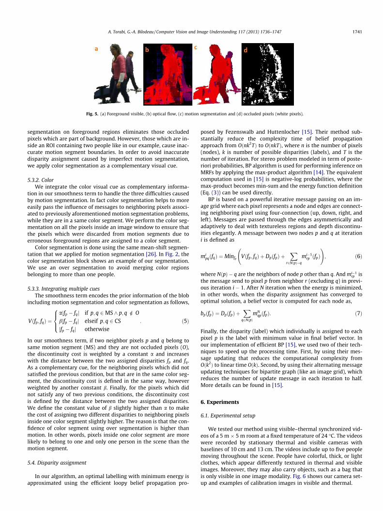
Fig. 5. (a) Foreground visible, (b) optical flow, (c) motion segmentation and (d) occluded pixels (white pixels).
A. Torabi, G.-A. Bilodeau / Computer Vision and Image Understanding 117 (2013) 1736–1747 1741
segmentation on foreground regions eliminates those occludedpixels which are part of background. However, those which are in-side an ROI containing two people like in our example, cause inac-curate motion segment boundaries. In order to avoid inaccuratedisparity assignment caused by imperfect motion segmentation,we apply color segmentation as a complementary visual cue.
5.3.2. ColorWe integrate the color visual cue as complementary informa-
tion in our smoothness term to handle the three difficulties causedby motion segmentation. In fact color segmentation helps to moreeasily pass the influence of messages to neighboring pixels associ-ated to previously aforementioned motion segmentation problems,while they are in a same color segment. We perform the color seg-mentation on all the pixels inside an image window to ensure thatthe pixels which were discarded from motion segments due toerroneous foreground regions are assigned to a color segment.
Color segmentation is done using the same mean-shift segmen-tation that we applied for motion segmentation [26]. In Fig. 2, thecolor segmentation block shows an example of our segmentation.We use an over segmentation to avoid merging color regionsbelonging to more than one people.
5.3.3. Integrating multiple cuesThe smoothness term encodes the prior information of the blob
including motion segmentation and color segmentation as follows,
Vðfp; fqÞ ¼ajfp � fqj if p; q 2MS ^ p; q R O
bjfp � fqj elseif p; q 2 CSjfp � fqj otherwise
8><>: : ð5Þ
In our smoothness term, if two neighbor pixels p and q belong tosame motion segment (MS) and they are not occluded pixels (O),the discontinuity cost is weighted by a constant a and increaseswith the distance between the two assigned disparities fp and fq.As a complementary cue, for the neighboring pixels which did notsatisfied the previous condition, but that are in the same color seg-ment, the discontinuity cost is defined in the same way, howeverweighted by another constant b. Finally, for the pixels which didnot satisfy any of two previous conditions, the discontinuity costis defined by the distance between the two assigned disparities.We define the constant value of b slightly higher than a to makethe cost of assigning two different disparities to neighboring pixelsinside one color segment slightly higher. The reason is that the con-fidence of color segment using over segmentation is higher thanmotion. In other words, pixels inside one color segment are morelikely to belong to one and only one person in the scene than themotion segment.
5.4. Disparity assignment
In our algorithm, an optimal labelling with minimum energy isapproximated using the efficient loopy belief propagation pro-
posed by Fezenswalb and Huttenlocher [15]. Their method sub-stantially reduce the complexity time of belief propagationapproach from Oðnk2TÞ to OðnkTÞ, where n is the number of pixels(nodes), k is number of possible disparities (labels), and T is thenumber of iteration. For stereo problem modeled in term of poste-riori probabilities, BP algorithm is used for performing inference onMRFs by applying the max-product algorithm [14]. The equivalentcomputation used in [15] is negative-log probabilities, where themax-product becomes min-sum and the energy function definition(Eq. (3)) can be used directly.
BP is based on a powerful iterative message passing on an im-age grid where each pixel represents a node and edges are connect-ing neighboring pixel using four-connection (up, down, right, andleft). Messages are passed through the edges asymmetrically andadaptively to deal with textureless regions and depth discontinu-ities elegantly. A message between two nodes p and q at iterationi is defined as
mipqðfqÞ ¼ Minfp Vðfp; fqÞ þ DpðfpÞ þ
Xr2NðpÞ�q
mi�1rp ðfpÞ
!; ð6Þ
where NðpÞ � q are the neighbors of node p other than q. And mi�1rp is
the message send to pixel p from neighbor r (excluding q) in previ-ous iteration i � 1. After N iteration when the energy is minimized,in other words, when the disparity assignment has converged tooptimal solution, a belief vector is computed for each node as,
bpðfpÞ ¼ DpðfpÞ þX
q2NðpÞmN
qpðfpÞ: ð7Þ
Finally, the disparity (label) which individually is assigned to eachpixel p is the label with minimum value in final belief vector. Inour implementation of efficient BP [15], we used two of their tech-niques to speed up the processing time. First, by using their mes-sage updating that reduces the computational complexity fromOðk2Þ to linear time OðkÞ. Second, by using their alternating messageupdating techniques for bipartite graph (like an image grid), whichreduces the number of update message in each iteration to half.More details can be found in [15].
6. Experiments
6.1. Experimental setup
We tested our method using visible–thermal synchronized vid-eos of a 5 m � 5 m room at a fixed temperature of 24 �C. The videoswere recorded by stationary thermal and visible cameras withbaselines of 10 cm and 13 cm. The videos include up to five peoplemoving throughout the scene. People have colorful, thick, or lightclothes, which appear differently textured in thermal and visibleimages. Moreover, they may also carry objects, such as a bag thatis only visible in one image modality. Fig. 6 shows our camera set-up and examples of calibration images in visible and thermal.

Fig. 6. (a) Camera setup. The halogen lights behind the cameras are used for calibration, (b) visible calibration image and (c) thermal calibration image.
Fig. 7. Detailed registration a person carrying a hot pot. (a) Foreground thermal image (green image), (b) foreground visible image (red image), and (c) registration of visibleimage on thermal image (overlayed red image on green image). (For interpretation of the references to color in this figure legend, the reader is referred to the web version ofthis article.)
Fig. 8. Detailed registration of a person carrying a bag. (a) Foreground thermal image (green image), (b) foreground visible image (red image), and (c) registration of visibleimage on thermal image (overlayed red image on green image). (For interpretation of the references to color in this figure legend, the reader is referred to the web version ofthis article.)
Fig. 9. Three examples of our tested video frames.
1742 A. Torabi, G.-A. Bilodeau / Computer Vision and Image Understanding 117 (2013) 1736–1747

A. Torabi, G.-A. Bilodeau / Computer Vision and Image Understanding 117 (2013) 1736–1747 1743
In order to simplify the matching to a 1D search, the thermaland visible cameras were calibrated using the standard method de-scribed in [27] and implemented in the camera calibration toolboxof MATLAB [28]. Since in the thermal images, the calibration check-board pattern is not visible at room temperature, we illuminatedthe scene using high intensity halogen bulbs placed behind thetwo cameras. In this way, the dark squares of the checkboard ab-sorb more energy and appear visually brighter than the whilesquares in the thermal images.
Figs. 7 and 8 illustrate two examples of successful registrationof visible image on thermal foreground images using our algo-rithm. Column (a) represents the foreground thermal image (greenimage), column (b) is foreground visible image (red image), and fi-nally column (c) displays the registered images (i.e. correctlyaligned and mis-aligned regions). Also, these two figures illustratethe benefit of combining thermal and visible information. Peopleare at different depth levels and with different clothing (such aswearing scarf or jacket). Background subtraction is imperfect andincludes false positive (shadows) and false negative (partial misde-tections) errors. In Fig. 7, a person carries a hot pot that is clearlydistinguishable in thermal image, but not as easy to detect in thevisible image. In Fig. 8, a person is carrying a bag at room temper-ature, and hence is not detected in the thermal image. Our globaloptimization approach has successfully estimated correct disparity
Fig. 10. Comparison of the disparity accuracy of LSS + DV and LSS + BP methods. Respec(second row), LSS + BP disparity map (thrid row), and sum disparity error (forth row) fo
for the bag region since it is connected to the person region in theimage.
In order to assess our registration for video surveillance applica-tions, we compared our proposed Local Self-Similarity based BeliefPropagation algorithm (LSS + BP) with the state-of-the-art MutualInformation based Disparity Voting algorithm (MI + DV) in [6]and with our previous work, Local Self-Similarity based registra-tion using DV matching (LSS + DV) in [10,4]. We focus on two mainaspects that demonstrate the efficiency of our method compared toprevious works: (1) depth discontinuity handling of occluding/oc-cluded people, and (2) the effect of different disparity ranges,whether small or large, on the registration performance. In the fol-lowing sections, we present our comparative evaluation regardingthese two aspects.
6.2. Evaluation of disparity and registration accuracy in occlusions
In order to demonstrate the disparity accuracy improvement ofour matching approach compared to state-of-the-art DV matchingapproaches [6,10,4] for occlusion handling, we quantitatively com-pared the disparity results of our proposed BP and of DV. In orderto perform a fair comparison, we use LSS as similarity measure inthe two approaches. We generated ground-truth disparities for vis-
tively columns (a), (b), and (c) are ground-truth (first row), LSS + DV disparity mapr visible foreground pixels of examples in Fig. 9.

Fig. 11. Comparison of LSS + DV and LSS + BP methods registration accuracy (large disparity range of [5–50] pixels): (a) LSS + BP detailed registration and (b) LSS + DVdetailed registration.
0 100 200 300 400 500 600 700 800 9000
0.1
0.2
0.3
0.4
0.5
0.6
Frame
Ove
rlapp
ing
erro
r LSS+BPMI+DV
a0 100 200 300 400 500 600 700 800 9000
0.1
0.2
0.3
0.4
0.5
0.6
Frame
Ove
rlapp
ing
erro
r LSS+BPLSS+DV
bFig. 12. Overlapping error using disparity range [2–20]: (a) LSS + BP vs. MI + DV and (b) LSS + BP vs. LSS + DV.
0 500 1000 1500 2000 2500 3000 3500 40000
0.10.20.30.40.50.60.70.80.9
11
Frame
Ove
rlapp
ing
erro
r LSS+BPMI+DV
a0 500 1000 1500 2000 2500 3000 3500 4000
00.10.20.30.40.50.60.70.80.9
11
Frame
Ove
rlapp
ing
erro
r
LSS+BPLSS+DV
bFig. 13. Overlapping error using a disparity range of [5–50]: (a) LSS + BP vs. MI + DV and (b) LSS + BP vs. LSS + DV.
1744 A. Torabi, G.-A. Bilodeau / Computer Vision and Image Understanding 117 (2013) 1736–1747
ible image by manually aligning visible foreground ROIs on corre-sponding thermal image.
Fig. 9 shows three example frames of our tested video. Unlikeprevious work [6], our tested videos are realistic videos containingpeople in different poses (e.g. sitting, bending, and walking) ratherthan only walking people. Accordingly, Fig. 10 illustrates the com-parison of disparity map for visible foreground pixels computed byLSS + BP and LSS + DV for three examples displayed in Fig. 9. InFig. 10, for better visualization, the disparity levels in disparitymaps are mapped to colors. Fig. 9 column (a) illustrates an example
where two people at two different depths in the scene appear in asingle region. The columns (b) and (c) show the examples wheremultiple people are occluded. Fig. 10, second row, shows LSS + DVmethod fails to assign correct different disparities to the columnscontaining pixels related to more than one disparity level in oc-cluded regions. In order to register people merged in a single re-gion, DV method makes no assumptions about the assignment ofpixels to individual person and assigns a single disparity to eachcolumn inside a ROI, based on a voting approach. If pixels on a col-umn of image belong to different objects at different depths in the
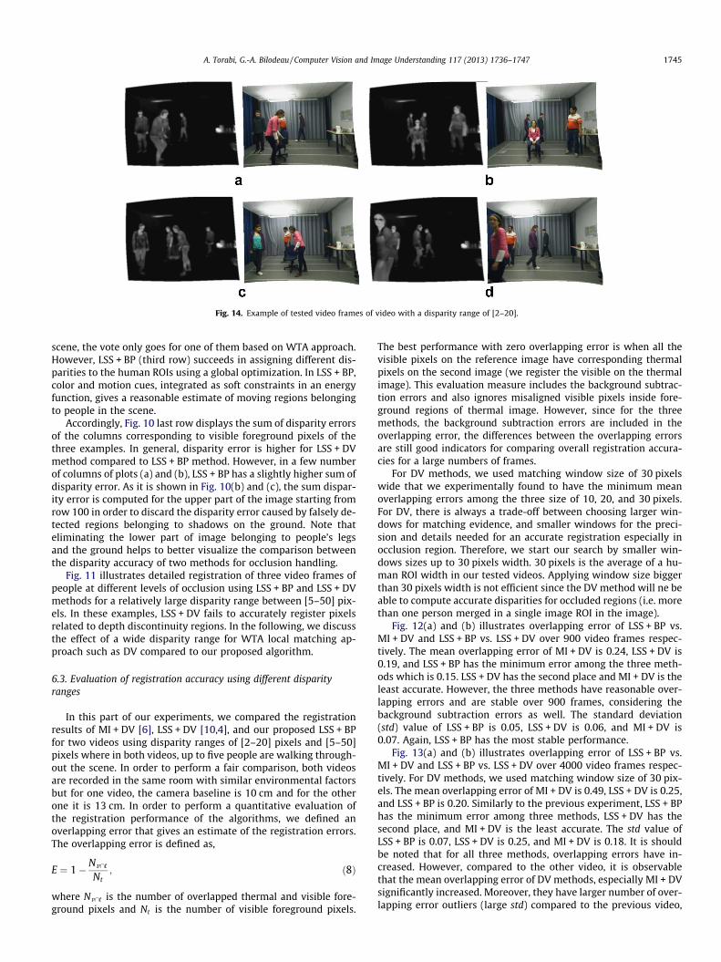
Fig. 14. Example of tested video frames of video with a disparity range of [2–20].
A. Torabi, G.-A. Bilodeau / Computer Vision and Image Understanding 117 (2013) 1736–1747 1745
scene, the vote only goes for one of them based on WTA approach.However, LSS + BP (third row) succeeds in assigning different dis-parities to the human ROIs using a global optimization. In LSS + BP,color and motion cues, integrated as soft constraints in an energyfunction, gives a reasonable estimate of moving regions belongingto people in the scene.
Accordingly, Fig. 10 last row displays the sum of disparity errorsof the columns corresponding to visible foreground pixels of thethree examples. In general, disparity error is higher for LSS + DVmethod compared to LSS + BP method. However, in a few numberof columns of plots (a) and (b), LSS + BP has a slightly higher sum ofdisparity error. As it is shown in Fig. 10(b) and (c), the sum dispar-ity error is computed for the upper part of the image starting fromrow 100 in order to discard the disparity error caused by falsely de-tected regions belonging to shadows on the ground. Note thateliminating the lower part of image belonging to people’s legsand the ground helps to better visualize the comparison betweenthe disparity accuracy of two methods for occlusion handling.
Fig. 11 illustrates detailed registration of three video frames ofpeople at different levels of occlusion using LSS + BP and LSS + DVmethods for a relatively large disparity range between [5–50] pix-els. In these examples, LSS + DV fails to accurately register pixelsrelated to depth discontinuity regions. In the following, we discussthe effect of a wide disparity range for WTA local matching ap-proach such as DV compared to our proposed algorithm.
6.3. Evaluation of registration accuracy using different disparityranges
In this part of our experiments, we compared the registrationresults of MI + DV [6], LSS + DV [10,4], and our proposed LSS + BPfor two videos using disparity ranges of [2–20] pixels and [5–50]pixels where in both videos, up to five people are walking through-out the scene. In order to perform a fair comparison, both videosare recorded in the same room with similar environmental factorsbut for one video, the camera baseline is 10 cm and for the otherone it is 13 cm. In order to perform a quantitative evaluation ofthe registration performance of the algorithms, we defined anoverlapping error that gives an estimate of the registration errors.The overlapping error is defined as,
E ¼ 1� Nv\t
Nt; ð8Þ
where Nv\t is the number of overlapped thermal and visible fore-ground pixels and Nt is the number of visible foreground pixels.
The best performance with zero overlapping error is when all thevisible pixels on the reference image have corresponding thermalpixels on the second image (we register the visible on the thermalimage). This evaluation measure includes the background subtrac-tion errors and also ignores misaligned visible pixels inside fore-ground regions of thermal image. However, since for the threemethods, the background subtraction errors are included in theoverlapping error, the differences between the overlapping errorsare still good indicators for comparing overall registration accura-cies for a large numbers of frames.
For DV methods, we used matching window size of 30 pixelswide that we experimentally found to have the minimum meanoverlapping errors among the three size of 10, 20, and 30 pixels.For DV, there is always a trade-off between choosing larger win-dows for matching evidence, and smaller windows for the preci-sion and details needed for an accurate registration especially inocclusion region. Therefore, we start our search by smaller win-dows sizes up to 30 pixels width. 30 pixels is the average of a hu-man ROI width in our tested videos. Applying window size biggerthan 30 pixels width is not efficient since the DV method will ne beable to compute accurate disparities for occluded regions (i.e. morethan one person merged in a single image ROI in the image).
Fig. 12(a) and (b) illustrates overlapping error of LSS + BP vs.MI + DV and LSS + BP vs. LSS + DV over 900 video frames respec-tively. The mean overlapping error of MI + DV is 0.24, LSS + DV is0.19, and LSS + BP has the minimum error among the three meth-ods which is 0.15. LSS + DV has the second place and MI + DV is theleast accurate. However, the three methods have reasonable over-lapping errors and are stable over 900 frames, considering thebackground subtraction errors as well. The standard deviation(std) value of LSS + BP is 0.05, LSS + DV is 0.06, and MI + DV is0.07. Again, LSS + BP has the most stable performance.
Fig. 13(a) and (b) illustrates overlapping error of LSS + BP vs.MI + DV and LSS + BP vs. LSS + DV over 4000 video frames respec-tively. For DV methods, we used matching window size of 30 pix-els. The mean overlapping error of MI + DV is 0.49, LSS + DV is 0.25,and LSS + BP is 0.20. Similarly to the previous experiment, LSS + BPhas the minimum error among three methods, LSS + DV has thesecond place, and MI + DV is the least accurate. The std value ofLSS + BP is 0.07, LSS + DV is 0.25, and MI + DV is 0.18. It is shouldbe noted that for all three methods, overlapping errors have in-creased. However, compared to the other video, it is observablethat the mean overlapping error of DV methods, especially MI + DVsignificantly increased. Moreover, they have larger number of over-lapping error outliers (large std) compared to the previous video,

Fig. 15. Qualitative comparison: (a) thermal foreground image (green image), (b) visible foreground image (red image), (c) disparity map LSS + BP, (d) disparity map LSS + DV,(e) disparity map MI + DV, (f) registration of visible on thermal LSS + BP, (g) registration of visible on thermal LSS + DV, and (h) registration of visible on thermal MI + DV. (Forinterpretation of the references to color in this figure legend, the reader is referred to the web version of this article.)
1746 A. Torabi, G.-A. Bilodeau / Computer Vision and Image Understanding 117 (2013) 1736–1747
which shows some performance instabilities over the whole video.Furthermore, LSS + DV performs better than MI + DV. This showsthat LSS used as similarity metric is a more robust feature for mul-timodal matching compared MI in the case of visible and infrared
images. BP + LSS was less influenced by the change of disparityrange.
The main reason of the significant performance decrease of DVmethods is that a larger disparity range used for horizontal match-
A. Torabi, G.-A. Bilodeau / Computer Vision and Image Understanding 117 (2013) 1736–1747 1747
ing increases the probability of false matching using a WTA ap-proach, especially for scenes with imperfect foreground regionsand corresponding regions that are differently textured in thermaland visible images. However, our proposed BP method that uses aBP global optimization approach is more robust, especially usinglarger disparity ranges. The overlapping error does not increasedramatically as the overlapping errors of DV methods.
Fig. 14 shows four examples of tested video frames using a dis-parity range of [2–20]. For these video frames, Fig. 15 illustratesqualitatively the resulting disparity maps, and registrations of vis-ible foreground image on thermal foreground image using LSS + BP,LSS + DV, and MI + DV. Fig. 15, rows (d) and (e) show the disparitymaps for the DV methods. In both methods, disparity assignmentsare inaccurate for depth discontinuity regions. However, LSS + DVcomputes more accurate disparity map. Fig. 15, rows (c) showsthe disparity map of LSS + BP method. It has more accurate results,especially for depth discontinuity regions. However, the last col-umn shows some color and motion over-segmentation for the per-son close to the camera that results in less smooth disparity mapinside the human body ROI compared to the farther objects.
7. Conclusions
In this paper, we proposed a stereo model for thermal–visiblepartial ROI registration using an efficient belief propagationalgorithm that outperforms previous state-of-the-art stereo regis-tration designed for close range video surveillance applications.We have tested our methods on two indoor videos, and presentedregistration results over 4900 frames. Our results demonstrate thatour method assigns more accurate disparity to pixels related todepth discontinuity regions and that it is more stable for large dis-parity range compared to previous works [6,10,4].
For video surveillance applications, processing time is animportant factor. The processing time of our algorithm for eachframe is approximately 2–6 s using a 3.40 GHz multi-core desktopprocessor, while for DV method, it is between 1 and 3 s. For bothmethods, the processing time varies based on the number and sizeof foreground ROIs in the images and as more people are in thefield of view of the cameras. Moreover, in our method, the numberof iterations of belief propagation algorithm varies for differentROIs depending on the rate of for converging to the minimum en-ergy (when between two consecutive iterations the energy overMRF nodes has not decreased). In our implementation we usedlookup tables and parallel processing programming (openMP) inC++ to speed up the processing time significantly.
The registered thermal and visible images obtained using ouralgorithm can be used for further data analysis including tracking,behaviour pattern analysis, and object categorization based on thecomplementary information provided by data fusion.
References
[1] Z. Zhu, T. Huang, Multimodal surveillance: an introduction, in: IEEE Conferenceon Computer Vision and Pattern Recognition, 2007 (CVPR ’07), 2007, pp. 1–6.
[2] R. Collins, A. Lipton, H. Fujiyoshi, T. Kanade, Algorithms for cooperativemultisensor surveillance, Proc. IEEE 89 (10) (2001) 1456–1477.
[3] D. Socolinsky, Design and deployment of visible–thermal biometricsurveillance systems, in: IEEE Conference on Computer Vision and PatternRecognition, 2007 (CVPR ’07), 2007, pp. 1–2.
[4] A. Torabi, G.-A. Bilodeau, Local self-similarity-based registration of human roisin pairs of stereo thermal–visible videos, Pattern Recogn. (2012).
[5] D. Scharstein, R. Szeliski, A taxonomy and evaluation of dense two-framestereo correspondence algorithms, Int. J. Comput. Vision 47 (2002) 7–42.
[6] S.J. Krotosky, M.M. Trivedi, Mutual information based registration ofmultimodal stereo videos for person tracking, Comput. Vision ImageUnderst. 106 (2–3) (2007) 270–287.
[7] E. Coiras, J. Santamaria, C. Miravet, Segment-based registration technique forvisual–infrared images, Opt. Eng. 39 (2000) 282–289.
[8] A. Torabi, G.-A. Bilodeau, An iterative integrated framework for thermalvisibleimage registration, sensor fusion, and people tracking for video surveillanceapplications, Comput. Vision Image Underst. 116 (2) (2012) 210–221.
[9] A. Torabi, G. Masse, G.-A. Bilodeau, Feedback scheme for thermal–visible videoregistration, sensor fusion, and people tracking, in: 2010 IEEE ComputerSociety Conference on Computer Vision and Pattern Recognition Workshops(CVPRW), 2010, pp. 15–22.
[10] A. Torabi, G.-A. Bilodeau, Local self-similarity as a dense stereo correspondencemeasure for themal–visible video registration, in: 2011 IEEE Computer SocietyConference on Computer Vision and Pattern Recognition Workshops (CVPRW),2011, pp. 61–67.
[11] A. Torabi, M. Najafianrazavi, G. Bilodeau, A comparative evaluation ofmultimodal dense stereo correspondence measures, in: 2011 IEEEInternational Symposium on Robotic and Sensors Environments (ROSE),2011, pp. 143–148.
[12] H.-M. Chen, P. Varshney, M.-A. Slamani, On registration of regions of interest(ROI) in video sequences, in: IEEE Conference on Advanced Video and SignalBased Surveillance (AVSS 2003), 2003, pp. 313–318.
[13] G. Egnal, Mutual Information as a Stereo Correspondence Measure, Tech. Rep.MS-CIS-00-20, University of Pennsylvania.
[14] J. Sun, N.-N. Zheng, H.-Y. Shum, Stereo matching using belief propagation, IEEETrans. Pattern Anal. Mach. Intell. 25 (7) (2003) 787–800.
[15] P.F. Felzenszwalb, D.P. Huttenlocher, Efficient belief propagation for earlyvision, Int. J. Comput. Vision 70 (2006) 41–54.
[16] Q. Yang, L. Wang, R. Yang, H. Stewenius, D. Nister, Stereo matching with color-weighted correlation hierarchical belief propagation, and occlusion handling,IEEE Trans. Pattern Anal. Mach. Intell. 31 (3) (2009) 492–504.
[17] Y. Boykov, O. Veksler, R. Zabih, Fast approximate energy minimization viagraph cuts, IEEE Trans. Pattern Anal. Mach. Intell. 23 (11) (2001) 1222–1239.
[18] M. Bleyer, M. Gelautz, Graph-cut-based stereo matching using imagesegmentation with symmetrical treatment of occlusions, Image Commun. 22(2007) 127–143.
[19] M. Tappen, W. Freeman, Comparison of graph cuts with belief propagation forstereo, using identical mrf parameters, in: Proceedings of the Ninth IEEEInternational Conference on Computer Vision, 2003, pp. 900–906.
[20] Q. Yang, L. Wang, N. Ahuja, A constant-space belief propagation algorithm forstereo matching, in: 2010 IEEE Conference on Computer Vision and PatternRecognition (CVPR), 2010, pp. 1458–1465.
[21] A. Klaus, M. Sormann, K. Karner, Segment-based stereo matching using beliefpropagation and a self-adapting dissimilarity measure, in: 18th InternationalConference on Pattern Recognition, 2006 (ICPR 2006), vol. 3, 2006, pp. 15–18.
[22] E. Shechtman, M. Irani, Matching local self-similarities across images andvideos, in: IEEE Conference on Computer Vision and Pattern Recognition (CVPR2007), 2007, pp. 1–8.
[23] P.O. Hoyer, P. Dayan, Non-negative matrix factorization with sparsenessconstraints, J. Mach. Learn. Res. 5 (2004) 1457–1469.
[24] B. Shoushtarian, H.E. Bez, A practical adaptive approach for dynamicbackground subtraction using an invariant colour model and object tracking,Pattern Recogn. Lett. 26 (1) (2005) 5–26.
[25] A. Ogale, Y. Aloimonos, A roadmap to the integration of early visual modules,Int. J. Comput. Vision 72 (2007) 9–25.
[26] D. Comaniciu, P. Meer, Mean shift analysis and applications, in: TheProceedings of the Seventh IEEE International Conference on ComputerVision (ICCV 1999), vol. 2, 1999, pp. 1197–1203.
[27] J. Heikkila, O. Silven, A four-step camera calibration procedure with implicitimage correction, in: Proceedings of the IEEE Computer Society Conference onComputer Vision and Pattern Recognition, 1997, pp. 1106–1112.
[28] J.-Y. Bouguet, Camera Calibration Toolbox for Matlab. <http://www.vision.caltech.edu/bouguetj/calib_doc/>.