A Low Impedance Marx Generator as a Test bed for - IOPscience
6
Journal of Physics: Conference Series OPEN ACCESS A Low Impedance Marx Generator as a Test bed for Vacuum Diodes To cite this article: Biswajit Adhikary et al 2012 J. Phys.: Conf. Ser. 390 012061 View the article online for updates and enhancements. You may also like Corona pre-ionized gas switches with an increased lifetime for Marx generator of the lightning test complex Yu A Bykov and E G Krastelev - Investigation of charge balance in ion accelerator TEMP–4M I P Khailov and V G Pak - High-voltage pulse generators for effective pumping of super-atmospheric pressure CO 2 -lasers B A Kozlov, D S Makhanko, V I Seredinov et al. - Recent citations Study on the frequency characteristics of nanogap electron devices Ji Xu et al - This content was downloaded from IP address 189.91.4.148 on 25/12/2021 at 14:53
Transcript of A Low Impedance Marx Generator as a Test bed for - IOPscience

Journal of Physics Conference Series
OPEN ACCESS
A Low Impedance Marx Generator as a Test bedfor Vacuum DiodesTo cite this article Biswajit Adhikary et al 2012 J Phys Conf Ser 390 012061
View the article online for updates and enhancements
You may also likeCorona pre-ionized gas switches with anincreased lifetime for Marx generator ofthe lightning test complexYu A Bykov and E G Krastelev
-
Investigation of charge balance in ionaccelerator TEMPndash4MI P Khailov and V G Pak
-
High-voltage pulse generators for effectivepumping of super-atmospheric pressureCO2-lasersB A Kozlov D S Makhanko V I Seredinovet al
-
Recent citationsStudy on the frequency characteristics ofnanogap electron devicesJi Xu et al
-
This content was downloaded from IP address 189914148 on 25122021 at 1453
A Low Impedance Marx Generator as a Test bed for Vacuum Diodes
Biswajit Adhikary P Deb RVerma R Shukla SKSharma PBanerjee R Das T Prabaharan BK Das and Anurag Shyam
Energetics and Electromagnetics Division Bhabha Atomic Research Centre Visakhapatnam India
E-mail biswajitadhikaryyahoocom
Abstract A low impedance Marx generator was developed which will serve as a test bed for Vacuum diodes of various electrode materials and geometries The vacuum diodes will be used for high power microwave generation The generator is capable to supply ~3GW of pulsed power to the vacuum diodes which is sufficient enough to produce plasma within the diode for electron beam generation A vacuum of 10-5Torr is required for virtual cathode formation within the diode when the beam current exceeds the space charge limiting current A vacuum diode of reflex triode geometry has been designed and vacuum of 10-5Torr has been achieved The repetitive operation of the vacuum diode depends upon the recovery of the diode the importance of the vacuum system on the recovery of the diode will be explained A vacuum system with high voltage isolator has been installed for getting the desired vacuum within the diode The design criterion of the vacuum system will be discussed The 300kV18kJ Marx generator which will power the vacuum diode has six stages with stage capacitance and voltage of 240nF and 50kV respectively It has an impedance of ~7 ohm and can deliver 200kV voltage across the diode in critically damped load condition The generator has a very fast rise time of 200nsThe operational characteristics of the Marx generator are determined experimentally The results have been analyzed and compared to an equivalent circuit model of the system
1 Introduction Intense pulsed relativistic electron beams (REB) is generated in a vacuum diode when a high voltage pulse is applied across the electrodes of the vacuum diode The relativistic electron beams has applications in wide variety of fields from high power microwave (HPM) generation flash X-ray generation pumping of lasers surface modification of materials etc Vacuum diodes require high voltage pulse A pulsed power driver has been developed to provide the high voltage pulse to the vacuum diode A typical pulsed power system that may deliver the pulsed power to the vacuum diode consists of a power supply to charge the Marx bank the Marx bank itself a pulse forming line (PFL) or conditioning circuit a peaking switch and at last Vacuum diode (Load) The PFL is required to sharpen the pulse to enhance the power as a typical Marx bank has slow rise times The PFL makes the system bulky and complex It also reduces the voltage at the load to half (if the impedance is matched) A Marx bank with a fast rise time can directly drive a vacuum diode (without using PFL) Such a system is more compact and more voltage can be delivered to the vacuum diode The vacuum diode chosen for this experiment was of reflex triode geometry
International Symposium on Vacuum Science amp Technology and its Application for Accelerators IOP PublishingJournal of Physics Conference Series 390 (2012) 012061 doi1010881742-65963901012061
Published under licence by IOP Publishing Ltd 1
2 Experimental set up The charging power supply the Marx bank and the vacuum diode constitute the whole system The system is compact enough to be truck loaded (Fig1)
Fig 1Marx bank with reflex triode
21 The Fast Marx bank To achieve a multi hundred kilo volt output a Marx bank is used due to itrsquos high energy storage capability The energy rating of the Marx bank is taken to be as 18kJ Six stages are used each with stage capacitance of 240nFThe capacitors are chosen for their availability physical dimensions and voltage rating of 50kV For the Marx bank to directly drive a vacuum diode a pulsed voltage of gt 200kV [1] is desirable Thus taking Vout = 200kV and choosing critically damped condition of Marx bank loading if n = no of stages V = stage charging voltage the output voltage is ~70 of nxV [2] So Vout = 07(nxV)Thus n = (200 x 103) 07 x 50 x 103 asymp 6 Thus with six stages the maximum erected open circuit voltage is 300kV and the stored energy rating is 18kJThe fast rise time of 200ns the system helped in uniform plasma formation on the cathode surface The fast rise time is achieved by reducing the inductance of the Marx circuit 22 The Vacuum diode The vacuum diode geometry chosen for these set of experiments is of lsquoreflex triodersquo for Virtual cathode oscillator (Vircator) mode of operation In the Vircator mode the high power electron beam from the diode is injected into an open propagation region in a vacuum of 10-5 mbar through a mesh When the beam current exceeds the space charge limiting current a space charge cloud called as lsquoVirtual Cathodersquo is formed The beam propagates for a certain distance and then reflects from the virtual cathode The oscillating electrons between the cathode and the virtual cathode generate electromagnetic radiation (HPM) A good vacuum system with fast pumping will remove the ablated material from the cathode and anode making the diode a fast recovery to be ready for the next high voltage pulse
3 Operation of The Marx bank The developed Marx generator has a design open-circuit voltage of 300 kV with an estimated FWHM pulse width close to 700 ns Energy rating of the Marx generator is 18 kJ so an estimated peak power of ~ 3 GW is expected from the device
International Symposium on Vacuum Science amp Technology and its Application for Accelerators IOP PublishingJournal of Physics Conference Series 390 (2012) 012061 doi1010881742-65963901012061
2
Fig 2 Vacuum diode of reflex triode geometry
With a charging voltage of 50 kV DC an open-circuit voltage of 300 kV is achieved The output voltage is measured by using spherical gaps with diameters of 150 mm The spherical gaps are used in place of the load to measure the open-circuit voltage of the Marx generator The 300 kV open-circuit output voltage of the Marx generator is confirmed by using a gap spacing of ~ 300 mm
A photograph of a shot taken by using the open-shutter digital camera with spherical gaps in place of the load is shown in Fig 3 Each spark gap at atmospheric pressure has a self-breakdown voltage of 12 kV approximately so the maximum output voltage which we can expect without pressurizing the spark gap is 72 kV To increase the charging voltage the gaps must be pressurized
Fig3 Marx generator (in open air) in operation is framed by a digital camera in the open shutter mode in which the shutter of the camera is left open and the room is kept dark The first light that it gets
(spark gap arcing light) is captured by it
31 Experimental results Short circuit mode of Marx bank operation After confirmation of the open-circuit voltage the Marx generator is loaded The voltage measurements are done by using a 20-MHz RC-compensated voltage probe with an attenuation factor of 100001 The waveforms are recorded on a 1-Ghz 2-Gss digital storage oscilloscope A negative pulse is obtained as it is to be connected to the cathode of the diode
International Symposium on Vacuum Science amp Technology and its Application for Accelerators IOP PublishingJournal of Physics Conference Series 390 (2012) 012061 doi1010881742-65963901012061
3
The Marx inductance is determined from the experimental results For finding it the Marx circuit is shorted without any load and charged to voltages of about 12 kV and the current waveform of 12 kA in the first peak is recorded using a current monitor The period T of the 1600 ns pulse is obtained from the current waveform (Fig 4)
MM CLT 2
Fig 4 Current waveform of the Marx generator operated in the short-circuit mode
where LM = 1500 nH amp CM = 40 nF Thus ZM = 625 Ω The estimated pulse width can be calculated as 80 of half the period of the short-circuit mode [2]
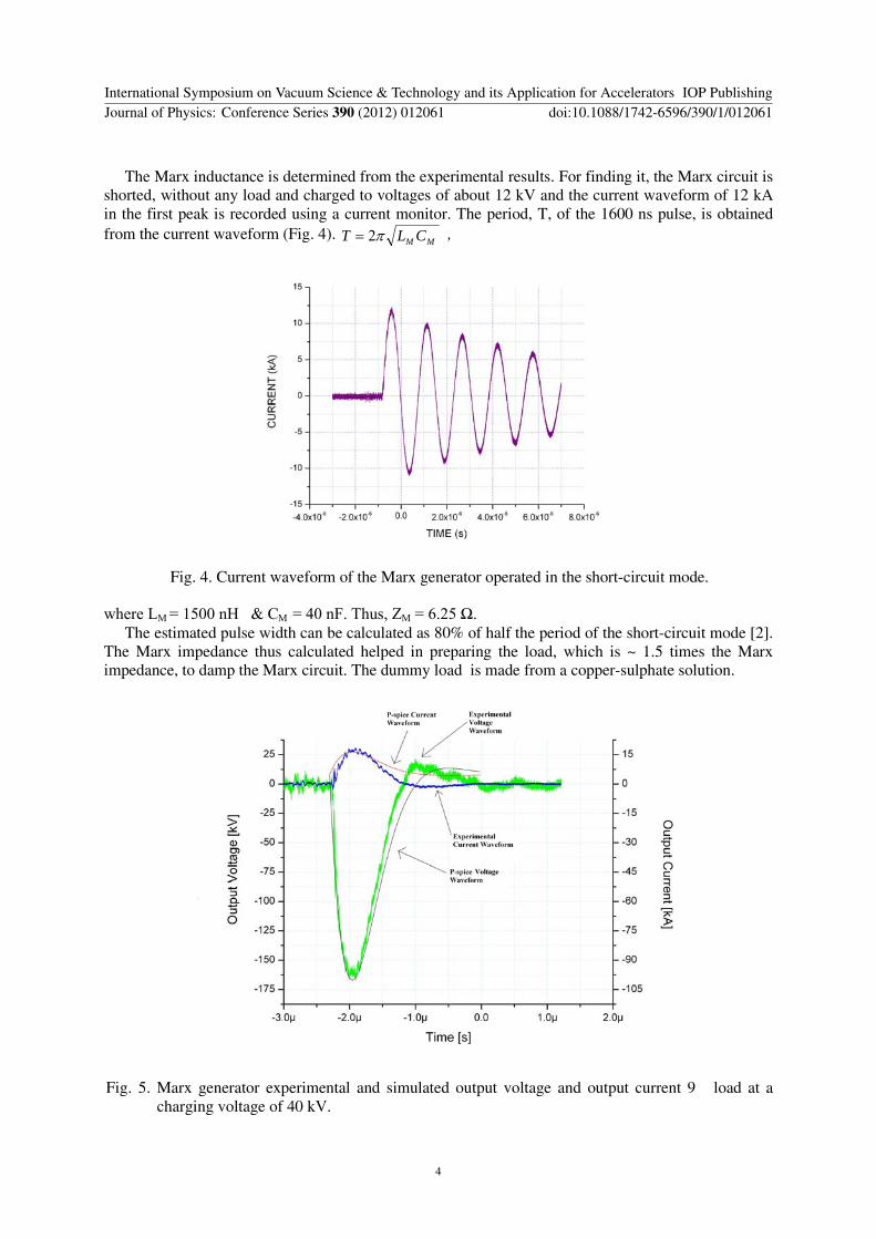
The Marx impedance thus calculated helped in preparing the load which is ~ 15 times the Marx impedance to damp the Marx circuit The dummy load is made from a copper-sulphate solution
Fig 5 Marx generator experimental and simulated output voltage and output current 9 load at a charging voltage of 40 kV
International Symposium on Vacuum Science amp Technology and its Application for Accelerators IOP PublishingJournal of Physics Conference Series 390 (2012) 012061 doi1010881742-65963901012061
4
Marx bank characterization on resistive load
The Marx output when measured with a load of 9 and charging voltage of 40kV is 163 kV which is ~ 68 of the open-circuit output voltage of 240 kV and the voltage reversal is ~ 10 The Marx output current is 18 kA The 9 load represents the damped load condition The rise time is 200 ns and FWHM pulse width is 640 ns So a pulsed power of ~ 3 GW is generated (see Fig 5)
Fig 6 Simulation circuit with a 9 load
4 Simulation The six stage Marx generator circuit is simulated in P-spice [3] The stage capacitance is 240 nF and the total inductance of the circuit is divided into 6 stages to give a stage inductance of 250 nH The spark gap capacitance is 32 femto F Because it is operating in open air the return conductor is kept a large distance away from the stage capacitor so the stray capacitance is taken to be negligible The simulated Marx circuit (Fig 6) delivers 157 kV 1875 kA to a 9-ohm load for a charging voltage of 40 kV Rise time is 200 ns Table 1 shows the results
Table 1 Results Charging Voltage
Experimental
Output VoltageCurrenttr(rise
time)
Simulated
OutputVoltage
Currenttr(rise time)
Load
Resistive
40 kV 163 kV18 kA200 ns 157 kV1875 kA200 ns 9 Ω
5 Summary A fast Marx bank has been developed which gives rise time of 200ns and pulsed power 3GW to the vacuum diode The vacuum diode of the reflex triode geometry is directly connected to the Marx bank with critically damped condition
References [1] Y J Chen MS Thesis Texas Tech University USA (2005) [2] WJCarey JR Mayes ldquoMarx generator design and performancerdquo Power Modulator
Symposium 2002 and 2002 High Voltage workshop Conference Record of the Twenty-fifth International 625 (2002)
[3] wwworcadcom (student version)
International Symposium on Vacuum Science amp Technology and its Application for Accelerators IOP PublishingJournal of Physics Conference Series 390 (2012) 012061 doi1010881742-65963901012061
5

A Low Impedance Marx Generator as a Test bed for Vacuum Diodes
Biswajit Adhikary P Deb RVerma R Shukla SKSharma PBanerjee R Das T Prabaharan BK Das and Anurag Shyam
Energetics and Electromagnetics Division Bhabha Atomic Research Centre Visakhapatnam India
E-mail biswajitadhikaryyahoocom
Abstract A low impedance Marx generator was developed which will serve as a test bed for Vacuum diodes of various electrode materials and geometries The vacuum diodes will be used for high power microwave generation The generator is capable to supply ~3GW of pulsed power to the vacuum diodes which is sufficient enough to produce plasma within the diode for electron beam generation A vacuum of 10-5Torr is required for virtual cathode formation within the diode when the beam current exceeds the space charge limiting current A vacuum diode of reflex triode geometry has been designed and vacuum of 10-5Torr has been achieved The repetitive operation of the vacuum diode depends upon the recovery of the diode the importance of the vacuum system on the recovery of the diode will be explained A vacuum system with high voltage isolator has been installed for getting the desired vacuum within the diode The design criterion of the vacuum system will be discussed The 300kV18kJ Marx generator which will power the vacuum diode has six stages with stage capacitance and voltage of 240nF and 50kV respectively It has an impedance of ~7 ohm and can deliver 200kV voltage across the diode in critically damped load condition The generator has a very fast rise time of 200nsThe operational characteristics of the Marx generator are determined experimentally The results have been analyzed and compared to an equivalent circuit model of the system
1 Introduction Intense pulsed relativistic electron beams (REB) is generated in a vacuum diode when a high voltage pulse is applied across the electrodes of the vacuum diode The relativistic electron beams has applications in wide variety of fields from high power microwave (HPM) generation flash X-ray generation pumping of lasers surface modification of materials etc Vacuum diodes require high voltage pulse A pulsed power driver has been developed to provide the high voltage pulse to the vacuum diode A typical pulsed power system that may deliver the pulsed power to the vacuum diode consists of a power supply to charge the Marx bank the Marx bank itself a pulse forming line (PFL) or conditioning circuit a peaking switch and at last Vacuum diode (Load) The PFL is required to sharpen the pulse to enhance the power as a typical Marx bank has slow rise times The PFL makes the system bulky and complex It also reduces the voltage at the load to half (if the impedance is matched) A Marx bank with a fast rise time can directly drive a vacuum diode (without using PFL) Such a system is more compact and more voltage can be delivered to the vacuum diode The vacuum diode chosen for this experiment was of reflex triode geometry
International Symposium on Vacuum Science amp Technology and its Application for Accelerators IOP PublishingJournal of Physics Conference Series 390 (2012) 012061 doi1010881742-65963901012061
Published under licence by IOP Publishing Ltd 1
2 Experimental set up The charging power supply the Marx bank and the vacuum diode constitute the whole system The system is compact enough to be truck loaded (Fig1)
Fig 1Marx bank with reflex triode
21 The Fast Marx bank To achieve a multi hundred kilo volt output a Marx bank is used due to itrsquos high energy storage capability The energy rating of the Marx bank is taken to be as 18kJ Six stages are used each with stage capacitance of 240nFThe capacitors are chosen for their availability physical dimensions and voltage rating of 50kV For the Marx bank to directly drive a vacuum diode a pulsed voltage of gt 200kV [1] is desirable Thus taking Vout = 200kV and choosing critically damped condition of Marx bank loading if n = no of stages V = stage charging voltage the output voltage is ~70 of nxV [2] So Vout = 07(nxV)Thus n = (200 x 103) 07 x 50 x 103 asymp 6 Thus with six stages the maximum erected open circuit voltage is 300kV and the stored energy rating is 18kJThe fast rise time of 200ns the system helped in uniform plasma formation on the cathode surface The fast rise time is achieved by reducing the inductance of the Marx circuit 22 The Vacuum diode The vacuum diode geometry chosen for these set of experiments is of lsquoreflex triodersquo for Virtual cathode oscillator (Vircator) mode of operation In the Vircator mode the high power electron beam from the diode is injected into an open propagation region in a vacuum of 10-5 mbar through a mesh When the beam current exceeds the space charge limiting current a space charge cloud called as lsquoVirtual Cathodersquo is formed The beam propagates for a certain distance and then reflects from the virtual cathode The oscillating electrons between the cathode and the virtual cathode generate electromagnetic radiation (HPM) A good vacuum system with fast pumping will remove the ablated material from the cathode and anode making the diode a fast recovery to be ready for the next high voltage pulse
3 Operation of The Marx bank The developed Marx generator has a design open-circuit voltage of 300 kV with an estimated FWHM pulse width close to 700 ns Energy rating of the Marx generator is 18 kJ so an estimated peak power of ~ 3 GW is expected from the device
International Symposium on Vacuum Science amp Technology and its Application for Accelerators IOP PublishingJournal of Physics Conference Series 390 (2012) 012061 doi1010881742-65963901012061
2
Fig 2 Vacuum diode of reflex triode geometry
With a charging voltage of 50 kV DC an open-circuit voltage of 300 kV is achieved The output voltage is measured by using spherical gaps with diameters of 150 mm The spherical gaps are used in place of the load to measure the open-circuit voltage of the Marx generator The 300 kV open-circuit output voltage of the Marx generator is confirmed by using a gap spacing of ~ 300 mm
A photograph of a shot taken by using the open-shutter digital camera with spherical gaps in place of the load is shown in Fig 3 Each spark gap at atmospheric pressure has a self-breakdown voltage of 12 kV approximately so the maximum output voltage which we can expect without pressurizing the spark gap is 72 kV To increase the charging voltage the gaps must be pressurized
Fig3 Marx generator (in open air) in operation is framed by a digital camera in the open shutter mode in which the shutter of the camera is left open and the room is kept dark The first light that it gets
(spark gap arcing light) is captured by it
31 Experimental results Short circuit mode of Marx bank operation After confirmation of the open-circuit voltage the Marx generator is loaded The voltage measurements are done by using a 20-MHz RC-compensated voltage probe with an attenuation factor of 100001 The waveforms are recorded on a 1-Ghz 2-Gss digital storage oscilloscope A negative pulse is obtained as it is to be connected to the cathode of the diode
International Symposium on Vacuum Science amp Technology and its Application for Accelerators IOP PublishingJournal of Physics Conference Series 390 (2012) 012061 doi1010881742-65963901012061
3
The Marx inductance is determined from the experimental results For finding it the Marx circuit is shorted without any load and charged to voltages of about 12 kV and the current waveform of 12 kA in the first peak is recorded using a current monitor The period T of the 1600 ns pulse is obtained from the current waveform (Fig 4)
MM CLT 2
Fig 4 Current waveform of the Marx generator operated in the short-circuit mode
where LM = 1500 nH amp CM = 40 nF Thus ZM = 625 Ω The estimated pulse width can be calculated as 80 of half the period of the short-circuit mode [2]
The Marx impedance thus calculated helped in preparing the load which is ~ 15 times the Marx impedance to damp the Marx circuit The dummy load is made from a copper-sulphate solution
Fig 5 Marx generator experimental and simulated output voltage and output current 9 load at a charging voltage of 40 kV
International Symposium on Vacuum Science amp Technology and its Application for Accelerators IOP PublishingJournal of Physics Conference Series 390 (2012) 012061 doi1010881742-65963901012061
4
Marx bank characterization on resistive load
The Marx output when measured with a load of 9 and charging voltage of 40kV is 163 kV which is ~ 68 of the open-circuit output voltage of 240 kV and the voltage reversal is ~ 10 The Marx output current is 18 kA The 9 load represents the damped load condition The rise time is 200 ns and FWHM pulse width is 640 ns So a pulsed power of ~ 3 GW is generated (see Fig 5)
Fig 6 Simulation circuit with a 9 load
4 Simulation The six stage Marx generator circuit is simulated in P-spice [3] The stage capacitance is 240 nF and the total inductance of the circuit is divided into 6 stages to give a stage inductance of 250 nH The spark gap capacitance is 32 femto F Because it is operating in open air the return conductor is kept a large distance away from the stage capacitor so the stray capacitance is taken to be negligible The simulated Marx circuit (Fig 6) delivers 157 kV 1875 kA to a 9-ohm load for a charging voltage of 40 kV Rise time is 200 ns Table 1 shows the results
Table 1 Results Charging Voltage
Experimental
Output VoltageCurrenttr(rise
time)
Simulated
OutputVoltage
Currenttr(rise time)
Load
Resistive
40 kV 163 kV18 kA200 ns 157 kV1875 kA200 ns 9 Ω
5 Summary A fast Marx bank has been developed which gives rise time of 200ns and pulsed power 3GW to the vacuum diode The vacuum diode of the reflex triode geometry is directly connected to the Marx bank with critically damped condition
References [1] Y J Chen MS Thesis Texas Tech University USA (2005) [2] WJCarey JR Mayes ldquoMarx generator design and performancerdquo Power Modulator
Symposium 2002 and 2002 High Voltage workshop Conference Record of the Twenty-fifth International 625 (2002)
[3] wwworcadcom (student version)
International Symposium on Vacuum Science amp Technology and its Application for Accelerators IOP PublishingJournal of Physics Conference Series 390 (2012) 012061 doi1010881742-65963901012061
5