A Lightweight Docking Station for a Hovering AUV
7
A Lightweight Docking Station for a Hovering AUV Nuno A. Cruz, Aníbal C. Matos, Rui M. Almeida and Bruno M. Ferreira Faculty of Engineering, University of Porto and INESC TEC [email protected], [email protected], [email protected], [email protected] Abstract—The concept of underwater docking stations has long been proposed to support the long term deployment of AUVs, but the number of successful solutions is still very disappointing. Hovering type AUVs can navigate arbitrarily slow, simplifying the docking maneuver and the requirements for the receiving structure. This paper describes a docking system that was developed to extend the mission duration of the MARES AUV, a man portable hovering type AUV. Given the wide range of operational scenarios and configurations of this AUV, one of the design requirements was to have a simple modular structure, that could easily be reconfigured to support different vehicle configurations, deployment scenarios and docking maneuvers. The paper provides details of the mechanical aspects, the onboard electronic subsystems, and the general operational procedure, as well as preliminary data from the first trials. I. I NTRODUCTION The concept of underwater docking stations has been sug- gested with the improvement of the operational level of AUVs, anticipating scenarios in which these autonomous vehicles could operate unattended for very long periods of time. Such underwater garages were idealized to charge batteries, to transfer information at high data rates, and also to provide shelter when sea state increased. Since most early AUVs were “flying type” vehicles, with horizontal propulsion and control fins, they had a minimum forward velocity to ensure controllability. This complicated dramatically the docking maneuver, as the vehicle had to home in some sort of docking cone or structure, demanding very high accuracy with a short time to process any local navigation data, often resulting in strong impacts with the receiving structure. Furthermore, all power and data transfers were also relatively complex with such configurations and this partly explains the relatively disappointing number of successful operational docking stations for flying type AUVs. Hovering type AUVs can navigate at arbitrarily low ve- locities, and most can even reverse velocity. This means that during a docking maneuver all data processing can be more complex, the vehicles can approach the docking structure only when the level of confidence is high, and they have many chances to retry the maneuver if needed. On the other hand, the vehicle configuration allows for other types of docking structure apart from the “docking cone”, for example sideways or in the vertical direction. This paper describes a docking system that was developed for the MARES AUV, a man portable hovering type AUV [1]. The main objective of the docking station is, naturally, to extend vehicle missions by providing means to charge the batteries and also to exchange large data files. The paper is organized as follows. Section II provides an overview of the main efforts that have been made to develop operational concepts of underwater docking stations for AUVs. Section III summarizes explicitly the main requirements for the development of this new docking station. Section IV details the components of the docking station, both in terms of mechanical arrangement and also in terms of electronic subsystems. Section VI describes the AUV components that are required to ensure a proper docking maneuver and an example of a possible docking algorithm or procedure using the system components. Finally, in Section VII we present the first results from our experimental validation, and lastly, in Section VIII we present some concluding remarks and future research directions. II. RELATED WORK Docking stations are generally seen as underwater garages for AUVs to recharge their batteries and exchange data, and they are fundamental for extended deployments at sea. They can be divided in four main types, depending on deployment configuration: Surface docks, bottom-mounted docks, hanging docks and towed docks. The type of dock is usually dictated by the operational scenario, therefore some multipurpose vehicles may require hybrid docks which can operate in different configurations. The design of a docking system is greatly influenced by the type of AUV, paying due attention to issues like robustness and stability. The first prototypes of underwater docking stations were designed for flying type AUVs, that would home in to a cone or pole, relying on ultra short baseline acoustics for the final approximation ( [2], [3]). This approach is still being perfected for flying type AUVs, with very good results in various operational conditions [4], [5]. In the last years, there has been a proliferation of hovering type AUVs, yielding a substantial increase in maneuverability. At the same time, current onboard processing capabilities permit real time analysis of complex data, like video images. This is fundamental to provide accurate data to feed a close range controller for the final docking sequence. In fact, and due to sensing constraints, the same technological solutions cannot be adopted for both long- and short-range relative localization. Long-range relative localization is typically achieved by means of ranging, bearing or a combination of both (see, for example, [6]–[8]). Using this sensing technology makes it possible
Transcript of A Lightweight Docking Station for a Hovering AUV
A Lightweight Docking Station fora Hovering AUV
Nuno A. Cruz, Aníbal C. Matos, Rui M. Almeida and Bruno M. FerreiraFaculty of Engineering, University of Porto and INESC TEC
[email protected], [email protected], [email protected], [email protected]
Abstract—The concept of underwater docking stations has longbeen proposed to support the long term deployment of AUVs,but the number of successful solutions is still very disappointing.Hovering type AUVs can navigate arbitrarily slow, simplifyingthe docking maneuver and the requirements for the receivingstructure. This paper describes a docking system that wasdeveloped to extend the mission duration of the MARES AUV,a man portable hovering type AUV. Given the wide range ofoperational scenarios and configurations of this AUV, one of thedesign requirements was to have a simple modular structure,that could easily be reconfigured to support different vehicleconfigurations, deployment scenarios and docking maneuvers.The paper provides details of the mechanical aspects, the onboardelectronic subsystems, and the general operational procedure, aswell as preliminary data from the first trials.
I. INTRODUCTION
The concept of underwater docking stations has been sug-gested with the improvement of the operational level of AUVs,anticipating scenarios in which these autonomous vehiclescould operate unattended for very long periods of time. Suchunderwater garages were idealized to charge batteries, totransfer information at high data rates, and also to provideshelter when sea state increased.
Since most early AUVs were “flying type” vehicles, withhorizontal propulsion and control fins, they had a minimumforward velocity to ensure controllability. This complicateddramatically the docking maneuver, as the vehicle had to homein some sort of docking cone or structure, demanding very highaccuracy with a short time to process any local navigation data,often resulting in strong impacts with the receiving structure.Furthermore, all power and data transfers were also relativelycomplex with such configurations and this partly explainsthe relatively disappointing number of successful operationaldocking stations for flying type AUVs.
Hovering type AUVs can navigate at arbitrarily low ve-locities, and most can even reverse velocity. This means thatduring a docking maneuver all data processing can be morecomplex, the vehicles can approach the docking structure onlywhen the level of confidence is high, and they have manychances to retry the maneuver if needed. On the other hand,the vehicle configuration allows for other types of dockingstructure apart from the “docking cone”, for example sidewaysor in the vertical direction.
This paper describes a docking system that was developedfor the MARES AUV, a man portable hovering type AUV[1]. The main objective of the docking station is, naturally,
to extend vehicle missions by providing means to charge thebatteries and also to exchange large data files.
The paper is organized as follows. Section II provides anoverview of the main efforts that have been made to developoperational concepts of underwater docking stations for AUVs.Section III summarizes explicitly the main requirements forthe development of this new docking station. Section IVdetails the components of the docking station, both in termsof mechanical arrangement and also in terms of electronicsubsystems. Section VI describes the AUV components thatare required to ensure a proper docking maneuver and anexample of a possible docking algorithm or procedure usingthe system components. Finally, in Section VII we present thefirst results from our experimental validation, and lastly, inSection VIII we present some concluding remarks and futureresearch directions.
II. RELATED WORK
Docking stations are generally seen as underwater garagesfor AUVs to recharge their batteries and exchange data, andthey are fundamental for extended deployments at sea. Theycan be divided in four main types, depending on deploymentconfiguration: Surface docks, bottom-mounted docks, hangingdocks and towed docks. The type of dock is usually dictated bythe operational scenario, therefore some multipurpose vehiclesmay require hybrid docks which can operate in differentconfigurations. The design of a docking system is greatlyinfluenced by the type of AUV, paying due attention to issueslike robustness and stability. The first prototypes of underwaterdocking stations were designed for flying type AUVs, thatwould home in to a cone or pole, relying on ultra short baselineacoustics for the final approximation ( [2], [3]). This approachis still being perfected for flying type AUVs, with very goodresults in various operational conditions [4], [5].
In the last years, there has been a proliferation of hoveringtype AUVs, yielding a substantial increase in maneuverability.At the same time, current onboard processing capabilitiespermit real time analysis of complex data, like video images.This is fundamental to provide accurate data to feed a closerange controller for the final docking sequence. In fact, and dueto sensing constraints, the same technological solutions cannotbe adopted for both long- and short-range relative localization.Long-range relative localization is typically achieved by meansof ranging, bearing or a combination of both (see, for example,[6]–[8]). Using this sensing technology makes it possible
to achieve errors in the order of some tens of centimeters,typically depending on the distance itself. This is enoughfor relatively long range navigation, with effective ranges upto a few kilometers. However, in short-range (less than afew meters), this localization approach becomes ineffectivebecause the error is too large for precise positioning. Com-plementarily, vision-based localization becomes more effectivein short-range, enabling accurate relative localization. Previousworks have validated this approach [9], [10], characterizing theerror using a visual marker and closing the loop by preciselypositioning an AUV relative to a marker.
This complementary navigation scheme has been the pre-ferred choice for most recent docking systems for hoveringAUVs [11]–[14]. In [12], it is assumed that the AUV is capableof performing smooth and very controlled movements. Thedocking procedure is accomplished by roughly approachingthe dock via acoustic guidance and switching to visual modeto complete the maneuver using two sets of visual markers.For power transfer, an underwater-pluggable connector is used.The connector is mounted between two guidance bolts. A lin-ear spindle engine is used to move the mechanism and coupleplug and socket. Two modified COTS WiFi routers are usedfor data transfer. Tests conducted in a water tank resulted inbandwidth of up to 30Mb/s across a distance of 8cm. Anotherdocking system for hovering type AUVs was presented in [13].The dock is a bottom-mounted open frame assembly equippedwith an acoustic transducer and a led marker. The dockingmethod requires an AUV fitted with acoustic positioning anda forward looking camera. The vehicle approaches the dockby acoustic localization and at a given distance it switchesto visual positioning. The docking maneuver is accomplishedrelatively to the LED marker, positioned in the dock’s frame.In [14], an underwater observatory with a docking systemfor long term environmental observation was described. Thedocking system is a sea-floor mounted version and is equippedwith guiding LEDs, a magnetic modem for communicationsand a wireless charging system. The AUV uses stereo camerasto detect the docks LEDs and perform the docking maneuver.With the vehicle in place up to 1kW of power is transferredthrough the wireless system and data transfer is assured by themagnetic modems.
III. SYSTEM REQUIREMENTS
The MARES AUV is a hovering type vehicle assembledwith 20cm diameter modular sections, resulting in lengthsbetween 1.5m and 2m, and weights between 30kg and 40kg.Part of the success of the MARES AUV is the portability andmodularity of the system, which have enabled the repeatedoperation in a wide range of scenarios. For the developmentof the docking station, the main purpose was to come up witha platform to test different docking approaches for this AUV.This allowed us to determine the main requirements for thesubsystems.
A. Main Operational Requirements
Given the wide range of operational scenarios and con-figurations of the MARES AUV, probably the main designrequirement was to have a simple modular structure thatcould easily be reconfigured to support different vehicleconfigurations, deployment scenarios and docking maneuvers.This had to be ensured with a low-logistics system, to matchthat of the AUV and allow a simple deployment of the overallsystem. Ideally, the docking station should be deployed andrecovered using a simple RHIB, which imposed considerablelimitations on size, weight, and general handling means.
We have translated these general guidelines into specificconstraints:
• lifting points for launch and recovery;• total weight in air less than 40kg;• maximum dimensions of 2m × 1m × 1m.
The envisaged operational scenarios were mainly for coastalwaters, up to a few tens of meters of depth, with deploymentslasting for a few days up to a few weeks (this exempted usfrom dealing with longer term issues like biofouling). Due tothe variability of sea bottom types that may be encountered,another operational requirement was to have real time accessto the attitude of the docking station, as well as a down-lookingcamera to perform a preliminary survey of the deploymentlocation, right before landing (eventually, a complimentaryaltimeter could be installed to yield a direct distance tobottom). This had to be complemented to a real time status ofthe internal system, like battery level and internal temperature.
Regarding external connections, the docking station shouldhave an Ethernet communication link, as well as an externalpower input to provide energy to the onboard electronics andcharge the backup batteries. Both connections should allow theinstallation onto existing local observatories, taking advantageof available infrastructures, or, alternatively, to a surface buoyproviding power and a gateway to shore.
In summary, these requirements led to another set of con-straints for our design:
• downward looking video camera and lights;• possibility of installing an altimeter;• cabled connection to shore/surface: communications and
power cable with a minimum of 30m;• backup battery for at least 2 hours of operation;• depth and attitude sensors;• internal health system (leak, battery level, temperature);• minimum 10 bar pressure hulls.
B. Docking Maneuvers
As described earlier, our modular structure should be ableto support multiple docking strategies, and the possibility ofplacing the dock on the sea bed, floating above sea bed onhanging from the surface. For the AUV to be able to dockin a given operational scenario, first it needs to be able tofind the dock. In fact, given the uncertainty associated withany underwater positioning system, it is virtually impossible

Fig. 1. Overview of the mechanical arrangement of the docking station.
to provide absolute coordinates of a [small] docking system,and expect an AUV to get to that exact position after travelinga few kilometers, for a few hours. For these reasons, we’vedecided to use a common approach, based on a complementarysystem with long range acoustic signals to approximate thedocking station, and a close range visual system to guide thevehicle during the final stage of the docking maneuver. Inorder to document docking and undocking maneuvers, a videocamera should also be installed on the docking structure. Videocould be recorded locally and/or transmitted in real time to thesurface.
In summary, the docking station should have some specificequipment to support the docking maneuvers:
• acoustic system for long range approach;• visual target for short range positioning and guidance;• lights to illuminate visual target;• mechanical guidance and a locking mechanism to hold
the AUV in place;• upward looking video camera to document AUV opera-
tions and general state
C. Requirements for Coupling
For practical reasons and robustness, all power transferand communications between the docking station and theAUV should be wireless. Moreover, the AUV should spenda minimum amount of energy while sitting at the dock, with
the required energy being provided by the docking station.At the same time, the AUV should be able to communicatewirelessly while at the dock, and, at the same time, receiveenergy to charge the on board batteries.
In summary, the docking system and the AUV should havea distributed system with the following requirements:
• locking mechanism to overcome the net buoyancy of theAUV, with a minimum force of 10N;
• short range wireless communications between the dock-ing station and the AUV;
• wireless power transfer from the docking station to theAUV.
IV. DOCKING STATION SUBSYSTEMS
For the development of the docking station, we have fulfilledthe above requirements with a mix of off-the-shelf parts andthe reuse of specific components from other projects. Thisensured a quick access to a working prototype that enabledthe parallel development and validation of different algorithmsand subsystems.
A. Mechanical Structure
The overall mechanical structure is based on modular alu-minum profiles, an easily reconfigurable system with manysolutions to attach sensors and actuators. A schematic repre-sentation can be seen in figure 1. The overall envelope of this
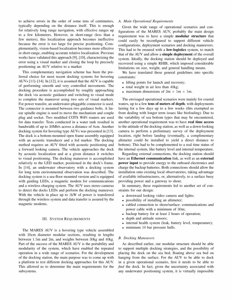
Fig. 2. Overview of the electronic subsystems and interconnections of the docking station.
configuration is 1.5m long, 0.8m wide and 1m high, with atotal weight close to 40kg. The initial structure was designedto land on the sea floor, with a low center of gravity adjustedwith ballast weights, although it can later be lowered from thesurface, if necessary. At the top layer, a docking cradle wasinstalled to hold the vehicle with the aid of two electromagnets.A visual target with 3 colored globes (red, yellow, green) isattached to the bottom of this structure, with sufficient offsetas to minimize visual occlusion during the docking maneuver.The geometry and location of the visual markers can be easilyadjusted, but our most common configuration is a triangularshape with 40cm of separation. An external LED light sourcewas also installed to illuminate the target if required. Alllocations and offsets can be easily changed in a few minutes,by adjusting only a few set screws.
A pressure vessel is located underneath the AUV cradle,holding all electronic boards and energy in an internal alu-minum frame. This pressure housing has the same design asthe housings for our range of modular AUVs, as described in[15]. It is a 50cm long, 20cm diameter, polyacetal cylinderthat withstands 20 bar of hydrostatic pressure. Using the samedesign as the AUVs’ pressure housings not only acceleratesdevelopment, but also facilitates the installation and test ofsensors for long periods of time prior to their integration onAUVs.
B. On Board Electronics
An overview of the electronic subsystems and interconnec-tions of the docking station can be seen in figure 2.
Inside the pressure housing, a simple single board computer(SBC) manages all subsystems, with the aid of a few OEMinterface boards. The current configuration is based on a
Raspberry Pi running Linux, with a solid state disk to log allactivities. These include time stamped data from sensors, aswell as a registry of actuation commands. The interface boardsconvert two of the USB ports of the SBC into RS232, RS485,and TTL serial, as required by the different subsystems.Although the pressure housing is connected to the surface, ithas its own Li-Po rechargeable batteries to ensure continuousautonomous operation. They provide a total of 110Wh at anominal voltage of 13.2V, and this voltage is converted downto 3.3V, 5V, and 12V, as required by the electronic subsystems.A simple internal supervision system monitors battery level,as well as other safety parameters like internal temperatureand water presence.
Specific to the docking maneuver are the devices used tofacilitate the identification of localization and pose of thedocking station by the AUV, including a set of visual markersand an acoustic system. The visual markers are illuminatedwith internal LEDs that can be dimmed as required to adaptto the local visibility conditions. The acoustic system has areceiver capable of decoding incoming frequencies, in therange of 20–30kHz, and a transmitter in the same range.Together, they can be used in different ways to supportmultiple localization approaches. If the system is configuredas a transponder, it will reply to a specific signal with anothersignal, allowing the "interrogator" to measure time of flightand therefore to estimate distance. This can serve to determinethe location of the docking system upon deployment, byranging from multiple known positions. During the AUVapproach to docking, this can also work for the AUV tohome to the target, using techniques called "single beaconnavigation".
At the final stage of the docking maneuver, the AUVslowly descends towards the cradle, and the electromagnetsare activated and hold the vehicle in position. The WirelessPower Transfer (WPT) system can then be powered, to transferenergy to the AUV. Additionally, the pressure housing alsoincludes a WiFi access point that allows close range commu-nication with the AUV when docked, to allow for AUV datadownload and new mission upload.
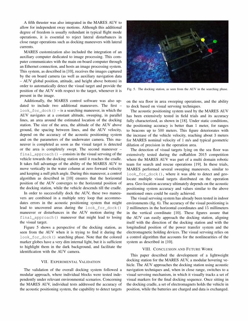
All these electronic boards are installed inside the pressurehousing, and there is still available volume for additionalsubsystems (fig. 3).
Fig. 3. Internal view of the pressure housing, with electronics and batteries.
C. Additional Devices
Taking advantage of the structural profiles and the real timelink with the surface, an IP camera was mounted on the docklooking up, so that it is possible to visually monitor all dockingoperation. At the same time, another camera was installedlooking down, to provide a simple means to assess the typeof sea bottom during deployment and, afterward, to documentany marine life in the vicinity of the docking station. Sincethe pressure vessel has many spare ports, it is straightforwardto support additional subsystems, like water quality sensors.
D. Surface Gateway
For the real time supervision of the docking maneuver, thereis a power and Ethernet cable linking the pressure housing ofthe docking station with the surface. At the surface, a WiFilink establishes the connection to a control interface (locatedon shore or on a mission support vessel).
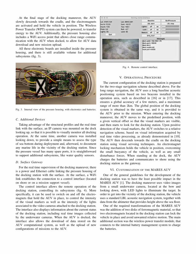
The control interface allows the remote operation of thedocking station, controlling its subsystems (fig. 4). Morespecifically, it can be used to switch on and off the electro-magnets that hold the AUV in place, to control the intensityof the visual markers as well as the intensity of the lightsassociated to the video cameras attached to the docking station.The interface also displays information about the current statusof the docking station, including real time images collectedby the underwater cameras. When the AUV is docked, theinterface also allows the download of data stored on theAUV computational system, as well as the upload of newconfigurations of missions to the AUV.
Fig. 4. Remote control interface.
V. OPERATIONAL PROCEDURE
The current configuration of the docking station is preparedfor the two-stage navigation scheme described above. For thelong range navigation, the AUV uses a long baseline acousticpositioning system based on two beacons installed in theoperation area, such as described in [16] or in [17]. Thisensures a global accuracy of a few meters, and a maximumrange of more than 2km. The global position of the dockingsystem is obtained in the same way, and it is provided tothe AUV prior to the mission. When entering the dockingmaneuver, the AUV moves to the predefined position, witha given vertical offset so that the visual markers are visible,and then starts to look for the docking station. Upon positivedetection of the visual markers, the AUV switches to a relativenavigation scheme, based on visual information acquired byreal time video processing, as already demonstrated in [10].The AUV then descends towards the cradle on the dockingstation using visual servoing techniques. An electromagnetlocking mechanism holds the vehicle in position, overcomingthe small buoyancy of the vehicle, as well as any smalldisturbance forces. When standing at the dock, the AUVcharges the batteries and communicates to shore using thedocking station as the gateway.
VI. CUSTOMIZATION OF THE MARES AUV
One of the general guidelines for the development of thedocking station was to have the least possible impact in theMARES AUV [1]. The docking maneuver uses video imagesfrom a small underwater camera, located at the bow andlooking down, with LED lights to illuminate the target. Inorder to get into the vicinity of the docking station, the vehicleuses a standard LBL acoustic navigation system, together withdata from the altimeter that provides height above the sea floor.
One of the required transformations of the MARES AUVwas the addition of two disks of ferromagnetic material, so thattwo electromagnets located in the docking station can lock thevehicle in place and avoid unwanted relative motion. The mainadditional section was the wireless power transfer module, thatconnects to the internal battery management system to chargethe batteries.
A fifth thruster was also integrated in the MARES AUV toallow for independent sway motions. Although this additionaldegree of freedom is usually redundant in typical flight modeoperations, it is essential to reject lateral disturbances inclose range operations such as docking maneuvers with lateralcurrents.
MARES customization also included the integration of anauxiliary computer dedicated to image processing. This com-puter communicates with the main on-board computer throughan Ethernet connection, and hosts an image processing system.This system, as described in [10], receives the images capturedby the on board camera (as well as auxiliary navigation data– AUV global position, attitude, and height above bottom) inorder to automatically detect the visual target and provide theposition of the AUV with respect to the target, whenever it ispresent in the image.
Additionally, the MARES control software was also up-dated to include two additional maneuvers. The first –look_for_dock() – is a searching maneuver, in which theAUV navigates at a constant altitude, sweeping, in parallellines, an area around the estimated location of the dockingstation. The size of the area, the altitude of the AUV aboveground, the spacing between lines, and the AUV velocity,depend on the accuracy of the acoustic positioning systemand on the parameters of the underwater camera. This ma-neuver is completed as soon as the visual target is detectedor the area is completely swept. The second maneuver –final_approach() – consists in the visual servoing of thevehicle towards the docking station until it reaches the cradle.It takes full advantage of the ability of the MARES AUV tomove vertically in the water column at zero forward velocityand keeping a null pitch angle. During this maneuver, a controlalgorithm as described in [10] ensures that the horizontalposition of the AUV converges to the horizontal position ofthe docking station, while the vehicle descends till the cradle.
In order to successfully dock the AUV, these two maneu-vers are combined in a multiple retry loop that accommo-dates errors in the acoustic positioning system that mightlead to uncovered areas during the look_for_dock()maneuver or disturbances in the AUV motion during thefinal_approach() maneuver that might lead to losingthe visual target.
Figure 5 shows a perspective of the docking station, asseen from the AUV when it is trying to find it during thelook_for_dock() searching phase. Note that the coloredmarker globes have a very dim internal light, but it is sufficientto highlight them in the dark background, and facilitate theidentification with the AUV camera.
VII. EXPERIMENTAL VALIDATION
The validation of the overall docking system followed amodular approach, where individual blocks were tested inde-pendently under relevant environmental scenarios. Concerningthe MARES AUV, individual tests addressed the accuracy ofthe acoustic positioning system, the capability to detect targets
Fig. 5. The docking station, as seen from the AUV in the searching phase.
on the sea floor in area sweeping operations, and the abilityto dock based on visual servoing techniques.
The acoustic positioning system used by the MARES AUVhas been extensively tested in field trials and its accuracyfully characterized, as shown in [18]. Under static conditions,the positioning accuracy is better than 1 meter, for rangesto beacons up to 500 meters. This figure deteriorates withthe increase of the vehicle velocity, reaching about 3 metersfor MARES nominal velocity of 1 m/s and typical geometricdilution of precision in the operation area.
The detection of visual targets lying on the sea floor wasextensively tested during the euRathlon 2015 competitionwhere the MARES AUV was part of a multi domain roboticteam for search and rescue operations [19]. In these trials,MARES performed several sweeping maneuvers, similar tolook_for_dock(), where it was able to detect and geo-locate multiple visual targets distributed on the operationarea. Geo-location accuracy ultimately depends on the acousticpositioning system accuracy and values similar to the abovementioned ones could be easily achieved.
The visual servoing system has already been tested in indoorenvironments (fig. 6). The accuracy of the visual positioning is2 millimeters in the horizontal coordinates and 15 millimetersin the vertical coordinate [10]. These figures assure thatthe AUV can easily approach the docking station, aligningitself with the direction of the docking station and with thelongitudinal position of the power transfer system and theelectromagnetic holding devices. The visual servoing relies ona control algorithm that accounts for the nonlinearities of thesystem as described in [10].
VIII. CONCLUSION AND FUTURE WORK
This paper described the development of a lightweightdocking station for the MARES AUV, a modular hovering ve-hicle. The AUV approaches the docking station using acousticnavigation techniques and, when in close range, switches to avisual servoing mechanism, in which it visually tracks a set ofvisual markers for the final docking sequence. Once sitting inthe docking cradle, a set of electromagnets holds the vehicle inposition, while the batteries are charged and data is exchanged.
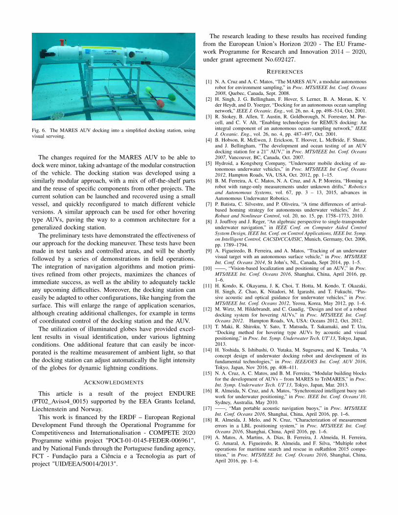
Fig. 6. The MARES AUV docking into a simplified docking station, usingvisual servoing.
The changes required for the MARES AUV to be able todock were minor, taking advantage of the modular constructionof the vehicle. The docking station was developed using asimilarly modular approach, with a mix of off-the-shelf partsand the reuse of specific components from other projects. Thecurrent solution can be launched and recovered using a smallvessel, and quickly reconfigured to match different vehicleversions. A similar approach can be used for other hoveringtype AUVs, paving the way to a common architecture for ageneralized docking station.
The preliminary tests have demonstrated the effectiveness ofour approach for the docking maneuver. These tests have beenmade in test tanks and controlled areas, and will be shortlyfollowed by a series of demonstrations in field operations.The integration of navigation algorithms and motion primi-tives refined from other projects, maximizes the chances ofimmediate success, as well as the ability to adequately tackleany upcoming difficulties. Moreover, the docking station caneasily be adapted to other configurations, like hanging from thesurface. This will enlarge the range of application scenarios,although creating additional challenges, for example in termsof coordinated control of the docking station and the AUV.
The utilization of illuminated globes have provided excel-lent results in visual identification, under various lightningconditions. One additional feature that can easily be incor-porated is the realtime measurement of ambient light, so thatthe docking station can adjust automatically the light intensityof the globes for dynamic lightning conditions.
ACKNOWLEDGMENTS
This article is a result of the project ENDURE(PT02_Aviso4_0015) supported by the EEA Grants Iceland,Liechtenstein and Norway.
This work is financed by the ERDF – European RegionalDevelopment Fund through the Operational Programme forCompetitiveness and Internationalisation - COMPETE 2020Programme within project "POCI-01-0145-FEDER-006961",and by National Funds through the Portuguese funding agency,FCT - Fundação para a Ciência e a Tecnologia as part ofproject "UID/EEA/50014/2013".
The research leading to these results has received fundingfrom the European Union’s Horizon 2020 - The EU Frame-work Programme for Research and Innovation 2014 − 2020,under grant agreement No.692427.
REFERENCES
[1] N. A. Cruz and A. C. Matos, “The MARES AUV, a modular autonomousrobot for environment sampling,” in Proc. MTS/IEEE Int. Conf. Oceans2008, Quebec, Canada, Sept. 2008.
[2] H. Singh, J. G. Bellingham, F. Hover, S. Lerner, B. A. Moran, K. V.der Heydt, and D. Yoerger, “Docking for an autonomous ocean samplingnetwork,” IEEE J. Oceanic. Eng., vol. 26, no. 4, pp. 498–514, Oct. 2001.
[3] R. Stokey, B. Allen, T. Austin, R. Goldborough, N. Forrester, M. Pur-cell, and C. V. Alt, “Enabling technologies for REMUS docking: Anintegral component of an autonomous ocean-sampling network,” IEEEJ. Oceanic. Eng., vol. 26, no. 4, pp. 487–497, Oct. 2001.
[4] B. Hobson, R. McEwen, J. Erickson, T. Hoover, L. McBride, F. Shane,and J. Bellingham, “The development and ocean testing of an AUVdocking station for a 21” AUV,” in Proc. MTS/IEEE Int. Conf. Oceans2007, Vancouver, BC, Canada, Oct. 2007.
[5] Hydroid, a Kongsberg Company, “Underwater mobile docking of au-tonomous underwater vehicles,” in Proc. MTS/IEEE Int Conf. Oceans2012, Hampton Roads, VA, USA, Oct. 2012, pp. 1–15.
[6] B. M. Ferreira, A. C. Matos, N. A. Cruz, and A. P. Moreira, “Homing arobot with range-only measurements under unknown drifts,” Roboticsand Autonomous Systems, vol. 67, pp. 3 – 13, 2015, advances inAutonomous Underwater Robotics.
[7] P. Batista, C. Silvestre, and P. Oliveira, “A time differences of arrival-based homing strategy for autonomous underwater vehicles,” Int. J.Robust and Nonlinear Control, vol. 20, no. 15, pp. 1758–1773, 2010.
[8] J. Jouffroy and J. Reger, “An algebraic perspective to single-transponderunderwater navigation,” in IEEE Conf. on Computer Aided ControlSystem Design, IEEE Int. Conf. on Control Applications, IEEE Int. Symp.on Intelligent Control, CACSD/CCA/ISIC, Munich, Germany, Oct. 2006,pp. 1789–1794.
[9] A. Figueiredo, B. Ferreira, and A. Matos, “Tracking of an underwatervisual target with an autonomous surface vehicle,” in Proc. MTS/IEEEInt. Conf. Oceans 2014, St John’s, NL, Canada, Sept 2014, pp. 1–5.
[10] ——, “Vision-based localization and positioning of an AUV,” in Proc.MTS/IEEE Int. Conf. Oceans 2016, Shanghai, China, April 2016, pp.1–6.
[11] H. Kondo, K. Okayama, J. K. Choi, T. Hotta, M. Kondo, T. Okazaki,H. Singh, Z. Chao, K. Nitadori, M. Igarashi, and T. Fukuchi, “Pas-sive acoustic and optical guidance for underwater vehicles,” in Proc.MTS/IEEE Int. Conf. Oceans 2012, Yeosu, Korea, May 2012, pp. 1–6.
[12] M. Wirtz, M. Hildebrandt, and C. Gaudig, “Design and test of a robustdocking system for hovering AUVs,” in Proc. MTS/IEEE Int. Conf.Oceans 2012. Hampton Roads, VA, USA: Oceans 2012, Oct. 2012.
[13] T. Maki, R. Shiroku, Y. Sato, T. Matsuda, T. Sakamaki, and T. Ura,“Docking method for hovering type AUVs by acoustic and visualpositioning,” in Proc. Int. Symp. Underwater Tech. UT’13, Tokyo, Japan,2013.
[14] H. Yoshida, S. Ishibashi, O. Yutaka, M. Sugesawa, and K. Tanaka, “Aconcept design of underwater docking robot and development of itsfundamental technologies,” in Proc. IEEE/OES Int. Conf. AUV 2016,Tokyo, Japan, Nov 2016, pp. 408–411.
[15] N. A. Cruz, A. C. Matos, and B. M. Ferreira, “Modular building blocksfor the development of AUVs – from MARES to TriMARES,” in Proc.Int. Symp. Underwater Tech. UT’13, Tokyo, Japan, Mar. 2013.
[16] R. Almeida, N. Cruz, and A. Matos, “Synchronized intelligent buoy net-work for underwater positioning,” in Proc. IEEE Int. Conf. Oceans’10,Sydney, Australia, May 2010.
[17] ——, “Man portable acoustic navigation buoys,” in Proc. MTS/IEEEInt. Conf. Oceans 2016, Shanghai, China, April 2016, pp. 1–6.
[18] R. Almeida, J. Melo, and N. Cruz, “Characterization of measurementerrors in a LBL positioning system,” in Proc. MTS/IEEE Int. Conf.Oceans 2016, Shanghai, China, April 2016, pp. 1–6.
[19] A. Matos, A. Martins, A. Dias, B. Ferreira, J. Almeida, H. Ferreira,G. Amaral, A. Figueiredo, R. Almeida, and F. Silva, “Multiple robotoperations for maritime search and rescue in euRathlon 2015 compe-tition,” in Proc. MTS/IEEE Int. Conf. Oceans 2016, Shanghai, China,April 2016, pp. 1–6.


![[inria-00202698, v1] Experiments in Navigation and Mapping ... · PDF fileExperiments in Navigation and Mapping with a Hovering AUV ... chaeological excavation to drill-rig maintenance](https://static.fdocuments.us/doc/165x107/5aa0e3e47f8b9a6c178ec0d1/inria-00202698-v1-experiments-in-navigation-and-mapping-in-navigation-and.jpg)