Flexible Thermal Protection System Development for Hypersonic Inflatable Aerodynamic Decelerators

A LIGHT-WEIGHT INFLATABLE HYPERSONICDRAG DEVICE FOR PLANETARY ENTRY
Angus D. McRonald,*Jet Propulsion Laboratory
California Institute of Technology
ABSTRACTThe author has analyzed the use of a light-weight inflatable hypersonic drag device,called a ballute, (balloon + parachute) forflight in planetary atmospheres, for entry,aerocapture, and aerobraking. Studies todate include missions to Mars, Venus,Earth, Saturn, Titan, Neptune and Pluto.Data on a Pluto lander and a Mars orbiterwill be presented to illustrate the concept.The main advantage of using a ballute is thataero deceleration and heating inatmospheric entry occurs at much smalleratmospheric density with a ballute thanwithout it. For example, if a ballute has adiameter 10 times as large as thespacecraft, for unchanged total mass, entryspeed and entry angle, the atmosphericdensity at peak convective heating isreduced by a factor of 100, reducing thepeak heating by a factor of 10 for thespacecraft, and a factor of about 30 for theballute. Consequently the entry payload(lander, orbiter, etc.) is subject to much lessheating, requires a much reduced thermalprotection system (possibly only an MLIblanket), and the spacecraft design istherefore relatively unchanged from itsvacuum counterpart. The heat flux on the
* A. D. McRonald is a Member of the TechnicalStaff at the Jet Propulsion Laboratory of theCalifornia Institute of Technology. His opinionsare his own. This work was performed at the JetPropulsion Laboratory and was funded byNASA. The paper was presented at theAssociation Aeronautique et Astrounatique deFrance Conference at Arcachon, France onMarch 16-18, 1999. Email:[email protected]
ballute is small enough to be radiated attemperatures below 800 K or so. Also, theheating may be reduced further because theballute enters at a more shallow angle, evenallowing for the increased delivery angleerror. Added advantages are a smallermass ratio of entry system to total entrymass, and freedom from the low-densityand transonic instability problems thatconventional rigid entry bodies suffer, sincethe vehicle attitude is determined by theballute, usually released at continuumconditions (hypersonic for an orbiter, andsubsonic for a lander). Also, for a landerthe range from entry to touchdown is less,offering a smaller footprint. The ballutederives an entry corridor for aerocapture byentering on a path that would lead tolanding, and releasing the ballute adaptively,responding to measured deceleration, at aspeed computed to achieve the desiredorbiter exit conditions. For a lander anaccurate landing point could be achieved byproviding the lander with a small glidingcapacity, using the large potential energyavailable from being subsonic at highaltitude. Alternatively the ballute can beretained to act as a parachute or soft-landing device, or to float the payload as abuoyant aerobot. As expected, the ballutehas smaller size for relatively small entryspeeds, such as for Mars, or for theextensive atmosphere of a low-gravityplanet such as Pluto. The author willdiscuss presently available ballute materialsand a development program ofaerodynamic tests and materials that would
2
be required for ballutes to achieve their fullpotential.
INTRODUCTION
A hypersonic drag device was first studiedin the late sixties by the GoodyearCompany in Ref. 1, and at Langley RC byNASA in Ref. 2, one objective being toassist the Viking landers decelerate duringMars entry. For the Viking task windtunnel tests were performed on two shapes,for which stability was a primeconsideration. The drag device, called aballute, was to be inflated at modesthypersonic speed some time after peakheating and deceleration. The ballutes wereheavy and were inflated at relatively lowspeed and high pressure.
A ballute inflated prior to entry was firststudied in Ref. 3, which proposed to use aballute to decelerate during entry intoVenus. One heavy ballute, weighing severalhundred kilograms, was inflated prior toentry, released after deceleration, andreplaced by another ballute used as anaerobot or buoyant platform. The authorsof Ref. 3 evaluated the convective heatingrate and its time integral, and computedhow much material was ablated from theentry ballute. They also compared severalcandidate materials for the entry ballute. Inrecent years many materials have becomecommercially available in very thin sheets,and some will take relatively hightemperatures, such as Kapton, up to 500C, and PBO (Polyboxoxazole, a liquidcrystal polymer), up to 600 C.
PRESENT STUDIES
The author made a first study of a ballutefor direct entry of a Neptune orbiter in1994, as an alternative to use of aconventional lifting vehicle. Trajectorieswere computed for various entry angles andballute sizes. It became apparent that anentry corridor for aerocapture could becreated by releasing the ballute whensufficient delta-V had been reached duringan atmospheric pass. After release theorbiter would fly on to exit the atmospherewith relatively little further delta-V. Onecan see that in a convective heating situationthe heating rate decreases greatly when aballute is used. For example, if the ballutediameter is ten times that of the orbiter, thedensity at which peak deceleration or peakheating is reached is reduced by a factor of100, so that the convective heating rate toboth the orbiter and the ballute is therebyreduced by a factor of 10. For the ballutean additional reduction of square root of10, about 3.1 comes from the large size,and a further reduction is probable for bothorbiter and ballute, due to the entry anglebeing reduced, and the altitude being muchgreater, likely to be in a region where thescale height is greater. One can note alsothat even for radiative heating there is areduction relative to the orbiteraerocapturing in a lifting body, since theabove reduction of 100 in density when aballute is used reduces the radiative heatingmore than the large ballute size increases it.The reduction in heating applies equally tothe case of entry, and here the ballutedecelerates the lander at much higheraltitude than the conventional rigid bodyentry vehicle. Thereafter the ballute may bereleased to achieve a rapid descent, or maybe retained to achieve a soft landing, or, ifthe ballute is filled with He, can become abuoyant vehicle prior to landing. Since

3
1994 studies have been made of ballutesfor aerocapture and entry into the planetsMars, Venus, Earth, Saturn and Pluto andthe moon Titan. Details of a Mars orbiterand a Pluto lander will be presented toillustrate the process.
The deceleration assumes constant
hypersonic Cd for the initial entry with theballute attached, and then for the orbiterflight after ballute release. The basicdeceleration equation is:
( )dAm
a CVdtdV
//5.0 2= (1)
where Va is the velocity, T is time, Cd isthe constant drag coefficient, A is the crosssection area, p/4 * D2, D is the diameterand m is the mass. The equation applies toboth ballute + orbiter and to orbiter alone,
with the appropriate values of m, Cd, Dand A.
BALLUTE SHAPE
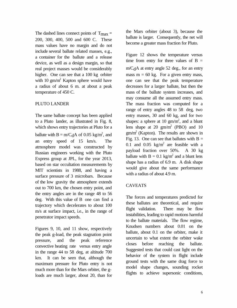
The first shape considered was a sphere,for which the flow features are relativelysimple and understood. The sphere may beinflated out of an orbiter, as shown in Fig.1,a, which has the advantage that theheating on the orbiter is the same as theballute, but has inconvenience in the vehiclelayout and in ballute release. A sphere letout astern on a tether, as in Fig. 1(b) ismore convenient, having little impact onorbiter design, and making ballute releaseeasy. The leading face and the corners ofthe orbiter require thermal protection withMLI (multi-layer insulation) of some nature.The ballutes shown in Fig. 1 show a net
enclosing them, to take the substantialaerodynamic drag force. A more efficientshape in terms of drag per unit mass isshown in Fig, 1(c) somewhat like a fat lens.
The drag coefficient, Cd is about 2,compared with 0.9 for a sphere, and theballute material mass is about one half, sothat a lens-shape ballute for a given task willbe about one half the diameter of aspherical ballute. A further reduction ofballute mass could be achieved by replacingthe lens shape by a disk, i.e., only one layerof material. Both the lens shape and thedisk require some help in deployment,possibly using inflatable tubing stretchingfrom the orbiter as shown, and including acircumferential ring. Although the lens andthe disk hold out the prospect of lower
mass and higher Cd, they have some morecomplex configurations to be analyzed.Also, the total mass of the ballute is madeup of a net enclosing the ballute, to take thesubstantial aerodynamic drag force, thefabric of the ballute, and gas to inflate thevolume of the sphere and the lens, and alsothe tubing. These vary differently withradius R: the net as R, the fabric as Rsquared, and the inflation gas as R cubed,so that the variation of total mass is a mixthat depends on size. For a very large entrymass the ballute radius R would becomelarge enough for the R cubed term tobecome significant or dominant. Forsmaller ballutes the fabric term varying as Rsquared is usually the main mass.
MARS ORBITER TRAJECTORIES
For the atmospheric pass for direct entry ofa micro-mission Mars orbiter, with entrymass about 100 kg, the basic approachwas to evaluate a number of entry

4
trajectories for different constant values of
ballistic coefficient, B = m/CdA, where m is
the entry mass, Cd is the hypersonic dragcoefficient (0.9 for a sphere) and A is thefrontal area. Trajectories were run for 7values of B, = 5, 2.5, 1.0, 0.5, 0.25 and0.1 kg/m2, and the delta-V loss for acomplete pass (no ballute release) is shownin Fig. 2 as a function of the entry angle,gamma. The entry speed was 5.5 km/s ataltitude 125 km, and the COSPAR nominalatmosphere model was used. Aerocaptureinto an elliptic orbit required a delta-V ofbetween about 500 and 2000 m/s, shownby the horizontal lines in Fig. 2. If the delta-V loss is less than about 500 m/s the vehiclewill exit in a hyperbolic trajectory. If thedelta-V loss is more than about 2000 m/sthe vehicle will enter, or possibly skip outbut re-enter. The mission designer usuallyseeks a fairly close circular orbit, so that thetarget delta-V is probably a little below2000 m/s. The amount by which the targetdelta-V differs from 2000 m/s will dependon the errors expected in entry angle andthe extent to which the atmospheric densitydeparts from the model used., and theability of the ballute release system topredict the delta-V at exit. A burn at thefirst apoapsis is necessary to lift theperiapse out of the atmosphere. Becauseof delivery error, computed to be about0.25 deg at the 2 sigma level, and possiblevariation in the atmosphere, one needs anentry corridor of about 0.6 deg from oneside to the other to accomplish aerocapturewith certainty. Figure 2 shows the delta-Vfor a complete atmospheric pass of theballute, whereas in actuality it is releasedwhen onboard deceleration readingsindicate that a chosen delta-V will beachieved by the orbiter at exit.
This concept is shown in more detail in Fig.3, which shows the speed V as a functionof entry angle, gamma, for five of thevehicle sizes. The group of curves marked(l) and (2) near the top of Fig. 3 show the
velocity V at maximum deceleration, gmax,and the value of V at minimum altitude,respectively. The vehicle number is markedon the trajectories. The remaining groupsof curves, marked (3), (4) and (5) all referto exit values of V respectively for thecases: (3) for ballute release at V = 4100m/s in the pass, as determined by themeasured time-integrated deceleration; (4)for ballute release at V = 3700 m/s, and (5)for no ballute release. For (3) and (4) theslope of the V at exit with entry angle ismuch less steep than when the ballute is
retained; the B = m/|CdA of the orbiterafter ballute release was assumed to be 30kg/m2; this value is probably about half thevalue for the orbiter alone, and it has beenassumed here that the orbiter will havesome part of the ballute deliberatelyretained to give it a stable attitude in theremainder of the atmospheric pass, or has askirt of some kind for the same purpose.One can see that an entry angle corridorwidth of 0.6 deg or more, as mentionedabove, is achieved for vehicles number 3, 4and 5, releasing the ballute at 4100 m/s.One wishes a small slope of the V exit valuewith angle gamma, so that a high B of theorbiter is desirable. In fact, an accurateballute exit V is achieved by two steps: (1)measure the actual delta-V loss as afunction of time, and (2) estimate the post-release orbiter delta-V loss on the basis ofthe onboard determination of the apparentnominal gamma, and release at the adaptive
5
delta-V loss designed to achieve accurateexit conditions.
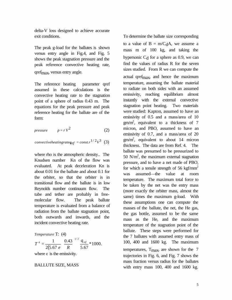
The peak g-load for the ballutes is shownversus entry angle in Fig.4, and Fig. 5shows the peak stagnation pressure and thepeak reference convective heating rate,
qrefmax, versus entry angle.
The reference heating parameter qrefassumed in these calculations is theconvective heating rate to the stagnationpoint of a sphere of radius 0.43 m. Theequations for the peak pressure and peakreference heating for the ballute are of theform:
pressure p = ρV 2 (2)
convectiveheatingrateqref = const.ρ1/ 2V3 (3)
where rho is the atmospheric density.. TheKnudsen number Kn of the flow wasevaluated. At peak deceleration Kn isabout 0.01 for the ballute and about 0.1 forthe orbiter, so that the orbiter is intransitional flow and the ballute is in lowReynolds number continuum flow. Thetube and tether are probably in free-molecular flow. The peak ballutetemperature is evaluated from a balance ofradiation from the ballute stagnation point,both outwards and inwards, and theincident convective heating rate.
Temperature T: (4)
( ).1000*
67.543.0
67.521 2/1
4 refq
RT
=
εwhere ε is the emissivity.
BALLUTE SIZE, MASS
To determine the ballute size corresponding
to a value of B = m/CdA, we assume amass m of 100 kg, and taking the
hypersonic Cd for a sphere as 0.9, we canfind the values of radius R for the sevensizes studied. From R we can compute the
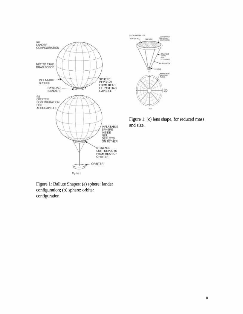
actual qrefmax, and hence the maximumtemperature, assuming the ballute materialto radiate on both sides with an assumedemissivity, reaching equilibrium almostinstantly with the external convectivestagnation point heating. Two materialswere studied: Kapton, assumed to have anemissivity of 0.5 and a mass/area of 10gm/m2, equivalent to a thickness of 7micron, and PBO, assumed to have anemissivity of 0.7, and a mass/area of 20gm/m2, equivalent to about 14 micronthickness. The data are from Ref. 4. Theballute was presumed to be pressurized to50 N/m2, the maximum external stagnationpressure, and to have a net made of PBO,for which a tensile strength of 56 kgf/mm2
was assumed—the value at roomtemperature. The maximum total force tobe taken by the net was the entry mass(more exactly the orbiter mass, almost thesame) times the maximum g-load. Withthese assumptions one can compute themasses of the ballute, the net, the He gas,the gas bottle, assumed to be the samemass as the He, and the maximumtemperature of the stagnation point of theballute. These steps were performed forthe 7 ballutes with assumed entry mass of100, 400 and 1600 kg. The maximum
temperatures, Tmax, are shown for the 7trajectories in Fig. 6, and Fig. 7 shows themass fraction versus radius for the balluteswith entry mass 100, 400 and 1600 kg.
6
The dashed lines connect points of Tmax =200, 300, 400, 500 and 600 C. Thesemass values have no margin and do notinclude several ballute related masses, e.g.,a container for the ballute and a releasedevice, as well as a design margin, so thatreal project masses would be considerablyhigher. One can see that a 100 kg orbiterwith 10 gm/m2 Kapton sphere would havea radius of about 6 m. at about a peaktemperature of 450 C.
PLUTO LANDER
The same ballute concept has been appliedto a Pluto lander, as illustrated in Fig. 8,which shows entry trajectories at Pluto for a
ballute with B = m/CdA of 0.05 kg/m2, andan entry speed of 15 km/s. Theatmosphere model was constructed byRussian engineers working with the PlutoExpress group at JPL, for the year 2013,based on star occultation measurements byMIT scientists in 1988, and having asurface pressure of 3 microbars. Becauseof the low gravity the atmosphere extendsout to 700 km, the chosen entry point, andthe entry angles are in the range 48 to 56deg. With this value of B one can find atrajectory which decelerates to about 100m/s at surface impact, i.e., in the range ofpenetrator impact speeds.
Figures 9, 10, and 11 show, respectivelythe peak g-load, the peak stagnation pointpressure, and the peak referenceconvective heating rate versus entry anglein the range 44 to 58 deg, at altitude 700km. It can be seen that, although themaximum pressure for Pluto entry is notmuch more than for the Mars orbiter, the g-loads are much larger, about 20, than for
the Mars orbiter (about 3), because theballute is larger. Consequently, the net willbecome a greater mass fraction for Pluto.
Figure 12 shows the temperature versustime from entry for three values of B =
m/CdA at entry angle 52 deg., for an entrymass m = 60 kg. For a given entry mass,one can see that the peak temperaturedecreases for a larger ballute, but then themass of the ballute system increases, andmay consume all the assumed entry mass.The mass fraction was computed for arange of entry angles 48 to 58 deg, twoentry masses, 30 and 60 kg, and for twoshapes: a sphere at 10 gm/m2, and a bluntlens shape at 20 gm/m2 (PBO) and 10gm/m2 (Kapton). The results are shown inFig. 13. One can see that ballutes with B =0.1 and 0.05 kg/m2 are feasible with apayload fraction over 50%. A 30 kgballute with B = 0.1 kg/m2 and a blunt lensshape has a radius of 6.9 m. A disk shapewould give about the same performancewith a radius of about 4.9 m.
CAVEATS
The forces and temperatures predicted forthese ballutes are theoretical, and requireflight validation. There may be flowinstabilities, leading to rapid motions harmfulto the ballute materials. The flow regime,Knudsen numbers about 0.01 on theballute, about 0.1 on the orbiter, make ituncertain to what extent the orbiter wakecloses before reaching the ballute.Suggested tests that could cast light on thebehavior of the system in flight includeground tests with the same drag force tomodel shape changes, sounding rocketflights to achieve supersonic conditions,

7
deployment and entry tests from an Arianepiggyback opportunity, and deploymentand entry tests out of the STS. Videocamera, accelerometers, pyrometers, colorchange paints, and film temperature gaugesare appropriate instrumentation, and alsoground tracking.
CONCLUSIONS
Entry ballutes have been studied for a Marsorbiter and for a Pluto lander, and theconclusions are that the concept offersadvantages in mass fraction and flexibility ofmission design over conventional entryvehicles and lifting vehicles for aerocapture.The studies indicate, for example, that onecan design a spherical ballute of radiusabout 6 m for a 100 kg Mars orbiter, and ablunt lens shape of ballute for a Pluto landerof radius about 6 m, for an entry mass of 30kg, with about 50% payload. If theconcepts described here prove to be
feasible in practical flight it would becomeeasier to design and implement atmosphericflights such as aerocapture and entry.
REFERENCES
1. I. M. Jahemenko, “BalluteCharacteristics in the 0.1 to 10 MachNumber Speed Range,” J. Spacecraft,Vol. 4, No. 8, 1058-63, August, 1967.
2. L. D. Guy, “Structural and DeceleratorDesign Options for Mars Entry,” J.Spacecraft, Vol. 6, No. 1, 44-49,January 1969.
3. H. Akiba et al., “Feasibility Study ofBuoyant Venus Station Placed byInflated Balloon Entry,” Paper at the27th Int. Conf. Astronomy, Anaheim,Calif., Oct., 1976.
4. A. Yavrouian et al., “High TemperatureMaterials for Venus BalloonEnvelopes,” AIAA Paper, 1995.
8
Figure 1: Ballute Shapes: (a) sphere: landerconfiguration; (b) sphere: orbiterconfiguration
Figure 1: (c) lens shape, for reduced massand size.

9
Figure 2. Delta-V loss for 7 ballute sizesversus entry angle.
Figure 3. Velocity V versus entry angle for5 of the ballute sizes: (1) circled showsvelocity V at maximum deceleration; (2)shows V at minimum altitude; (3) and (4)show exit V for ballute release at 4100 m/sand 3700 m/s, respectively; (5) shows exitV when ballute is not released.

10
Figure 4. Peak g-load versus entry anglefor the 7 ballutes.
Figure 5. Peak stagnation pressure andpeak reference convective heating rate forthe ballutes versus entry angle.
11
Figure 6. Peak temperature for the ballutesversus ballute radius, for PBO and Kapton,for entry mass values of 100, 400 and 1600kg.
Figure 7. Mass fraction of the ballutesystem (net, ballute, gas, bottle) versusballute radius, for PBO and Kapton, forentry mass 100, 400 and 1600 kg.

12
Figure 8. Entry trajectories at Pluto forentry angles 46, 48 and 56 deg, at entry
speed 15 km/s, and B = m/CdA = 0.05kg/m2.
Figure 9. Peak g-load for Pluto entry
versus entry angle, for ballutes with m/CdA= 0.025, 0.05 and 0.10 kg/m2.

13
Figure 10. Peak stagnation point pressurefor Pluto entry versus entry angle, for
ballutes with m/CdA = 0.025, 0.05, and0.1 kg/m2.
Figure 11. Peak reference stagnation point
heating rate, qrefmax versus entry angle, for
ballutes with m/CdA = 0.025, 0.05 and0.10 kg/m2.

14
Figure 12. Temperature versus time fromentry for entry angle 52 deg, entry mass 60
kg and m/CdA = 0.025, 0.05 and 0.10kg/m2.
Fig. 13. Mass fraction: ratio of ballutesystem mass to entry mass, for entry mass60 and 30 kg, Kapton sphere, and Kaptonand PBO lens shape.