A knowledge-based system for the conceptual design of ...€¦ · the term “knowledge-aided...
13
A knowledge-based system for the conceptual design of grippers for handling fabrics V.C. MOULIANITIS,A.J. DENTSORAS, and N.A. ASPRAGATHOS University of Patras, Mechanical Engineering and Aeronautics Department, 26500 Patras, Greece (Received December 16, 1997; Accepted October 20, 1998! Abstract The paper presents a knowledge-based system ~ KBS! for the conceptual design of grippers for handling fabrics. Its main purpose is the integration of the domain knowledge in a single system for the systematic design of this type of grippers. The knowledge presented, in terms of gripper, material and handling process, are classified. The reasoning strategy is based upon a combination of a depth-first search method and a heuristic method. The heuristic search method finds a final solution from a given set of feasible solutions and can synthesize new solutions to accomplish the required specifications. Details of the main features of the system are given, including its ability to take critical design decisions according to four criteria, weighted by the designer. The knowledge-based system was implemented in the Kappa P. C. 2.3.2 environment. Two examples are given to illustrate some critical aspects concerning the KBS development, to explain the operation of the proposed searching heuristic method, and to show its effectiveness in producing design concepts for grippers. Keywords: Knowledge-based Systems; Design; Fabrics 1. INTRODUCTION A gripper is a key component of a robotic workcell. Correct design of a gripper is extremely important for the success of a robotic handling task and can reduce the cost of the workcell. Design of grippers is an engineering task where many factors have to be considered for obtaining successful results. Any computational design tool, and more specific, a knowledge-based system ~ KBS! containing up-to-date de- sign knowledge would contribute toward this direction. According to Dym ~1994!, recent advances in the field of artificial intelligence ~AI !, particularly symbolic represen- tation and related problem-solving methods, offers signifi- cant opportunities to clarify and articulate concepts of design so as to lay a better framework for design research. Design activities encompass a spectrum from routine design, through variant design, to truly creative design of new artifacts. While routine design is possible to be computable, it is difficult to model creative design. According to Green ~1992!, comput- ers, currently, play two roles in design. One set of tools aids in the final drafting of the specifications and the second in analysis. Both of them are used long after designers have made their major decisions, and cannot recognize why a can- didate design failed or what changes are required. He coined the term “knowledge-aided design” ~ KAD! to contrast the current computer-aided design ~CAD! tools. While CAD tools are used only after the major design decisions have been made, KAD systems operate at a much earlier stage in the design process, when engineers make the major—and more critical—decisions. A few papers concerning CAD of grippers have appeared in the literature. Pham and Tacgin ~1992b) developed a hy- brid expert system for the detailed selection of robot grip- pers. The main objective of the system is to assist the user in choosing suitable grippers for industrial tasks varying from a simple pick-and-place operation to more sophisticated pro- cesses such as mechanical assembly. The system consists of two parts dealing with preliminary and detailed choices. In both parts, the Bayesian uncertainty technique is used to rank the proposed items and an adaptive learning algorithm is pro- vided to capture the user’s expertise during a consultation. In the preliminary choice section, suitable gripper types are suggested according to the general requirements of the Reprint requests to: V.C. Moulianitis, University of Patras, Mechanical Engineering and Aeronautics Department, 26500 Patras, Greece. Phone: 130 ~61! - 997268; Fax: 130 ~61! - 991626; E-mail: moulian@mech. upatras.gr.; [email protected].; [email protected] Artificial Intelligence for Engineering Design, Analysis and Manufacturing ~1999!, 13, 13–25. Printed in the USA. Copyright © 1999 Cambridge University Press 0890-0604099 $12.50 13
-
Upload
vuonghuong -
Category
Documents
-
view
219 -
download
0
Transcript of A knowledge-based system for the conceptual design of ...€¦ · the term “knowledge-aided...

A knowledge-based system for the conceptualdesign of grippers for handling fabrics
V.C. MOULIANITIS, A.J. DENTSORAS,and N.A. ASPRAGATHOSUniversity of Patras, Mechanical Engineering and Aeronautics Department, 26500 Patras, Greece
(Received December 16, 1997;Accepted October 20, 1998!
Abstract
The paper presents a knowledge-based system~KBS! for the conceptual design of grippers for handling fabrics. Itsmain purpose is the integration of the domain knowledge in a single system for the systematic design of this type ofgrippers. The knowledge presented, in terms of gripper, material and handling process, are classified. The reasoningstrategy is based upon a combination of a depth-first search method and a heuristic method. The heuristic search methodfinds a final solution from a given set of feasible solutions and can synthesize new solutions to accomplish the requiredspecifications. Details of the main features of the system are given, including its ability to take critical design decisionsaccording to four criteria, weighted by the designer. The knowledge-based system was implemented in the Kappa P. C.2.3.2 environment. Two examples are given to illustrate some critical aspects concerning the KBS development, toexplain the operation of the proposed searching heuristic method, and to show its effectiveness in producing designconcepts for grippers.
Keywords: Knowledge-based Systems; Design; Fabrics
1. INTRODUCTION
A gripper is a key component of a robotic workcell. Correctdesign of a gripper is extremely important for the successof a robotic handling task and can reduce the cost of theworkcell. Design of grippers is an engineering task wheremany factors have to be considered for obtaining successfulresults. Any computational design tool, and more specific,a knowledge-based system~KBS! containing up-to-date de-sign knowledge would contribute toward this direction.
According to Dym~1994!, recent advances in the field ofartificial intelligence~AI !, particularly symbolic represen-tation and related problem-solving methods, offers signifi-cant opportunities to clarify and articulate concepts of designso as to lay a better framework for design research. Designactivities encompass a spectrum from routine design, throughvariant design, to truly creative design of new artifacts. Whileroutine design is possible to be computable, it is difficult tomodel creative design. According to Green~1992!, comput-
ers, currently, play two roles in design. One set of tools aidsin the final drafting of the specifications and the second inanalysis. Both of them are used long after designers havemade their major decisions, and cannot recognize why a can-didate design failed or what changes are required. He coinedthe term “knowledge-aided design”~KAD ! to contrast thecurrent computer-aided design~CAD! tools. While CADtools are used only after the major design decisions havebeen made, KAD systems operate at a much earlier stage inthe design process, when engineers make the major—andmore critical—decisions.
A few papers concerning CAD of grippers have appearedin the literature. Pham and Tacgin~1992b) developed a hy-brid expert system for the detailed selection of robot grip-pers. The main objective of the system is to assist the userin choosing suitable grippers for industrial tasks varying froma simple pick-and-place operation to more sophisticated pro-cesses such as mechanical assembly. The system consists oftwo parts dealing with preliminary and detailed choices. Inboth parts, the Bayesian uncertainty technique is used to rankthe proposed items and an adaptive learning algorithm is pro-vided to capture the user’s expertise during a consultation.
In the preliminary choice section, suitable gripper typesare suggested according to the general requirements of the
Reprint requests to: V.C. Moulianitis, University of Patras, MechanicalEngineering and Aeronautics Department, 26500 Patras, Greece. Phone:130 ~61! - 997268; Fax:130 ~61! - 991626; E-mail: [email protected].; [email protected].; [email protected]
Artificial Intelligence for Engineering Design, Analysis and Manufacturing~1999!, 13, 13–25. Printed in the USA.Copyright © 1999 Cambridge University Press 0890-0604099 $12.50
13
user. The grippers available at this stage are categorized intothree groups namely, clamping, flexible, and single surfacegrippers~Pham & Tacgin, 1992a). A clamping gripper holdsa component by applying, externally or internally, pressureto more than one face of the latter. Two-jaw and three-jawgrippers are the most common types of this group. The term“flexible” refers to the ability of a single gripper to adapt itsform according to the shape of the component to be grasped.The flexible gripper types used are multifingered, soft, blad-der and adjustable jaws grippers. Single-surface grippers areselected in situations where only one surface of the work-piece is available for gripping and they are categorized asmagnetic, vacuum, and adhesive grippers. The detailed se-lection of the gripper is made from two commercial avail-able catalogs~Pham & Tacgin, 1991!, using information ofthe robot, the component to be handled, and the exact taskto be accomplished.
Heilala et al.~1992! developed a systematic mechatronicdesign concept for industrial grippers that speed up and im-prove the design of them. The design process starts with theclarification of the task. The specifications of the problemare found through the creation of a hierarchical list, whichcontains significant problems concerning the application.This list is refined and after the evaluation of the criticalfactors leads to the final specification list. In the conceptual-design phase, the gripper needs to be conceptualized, sen-sors and control systems have to be taken into consideration,as well as the robot itself.
There are two major motivations for the development ofthe present KBS: The integration—for the first time—of theavailable knowledge in a single system, and the systematicdesign of the grippers for handling fabrics. The design pro-cess ends with the conceptualization of the gripper~operat-
ing principle, control method, type of gripper, etc.!. Theresulting concept is not simply a selection among commer-cially available grippers, but, when required, a combinationof operating principles and handling techniques for a newgripping concept. Additionally, the system aims toward thedetermination of the auxiliary equipment of the gripper, atask that has not been discussed in the papers previouslymentioned. The final solution is chosen from a set of feasi-ble solutions by applying operating criteria weighted by thedesigner.
Next, a detailed presentation of the knowledge used isgiven. This knowledge refers to the various concepts of grip-pers and the relevant features of the fabrics, as well as tothe handling process itself. The KBS was built in a KappaP.C. 2.3.2 environment, a commercially available expert-system shell. In addition, techniques for the search of thesolutions and a list of criteria for the final selection from aset of solutions have been introduced. Two examples arealso presented to show the efficiency of the KBS. The con-cluding remarks refer to the usefulness of the system thatprovides “expert-quality” performance and acts as an advi-sor when engineers have to take critical decisions concern-ing the design of grippers.
2. THE DESIGN OF GRIPPERS—THE DOMAIN KNOWLEDGE
Generally, the design process follows three main steps: spec-ification development0planning phase, conceptual design,and detailed design~Ullman, 1992!. The goal of the speci-fication development0planning phase is to understand thedesign problem, generate engineering requirements, and es-tablish targets and plans for the design. Understanding the
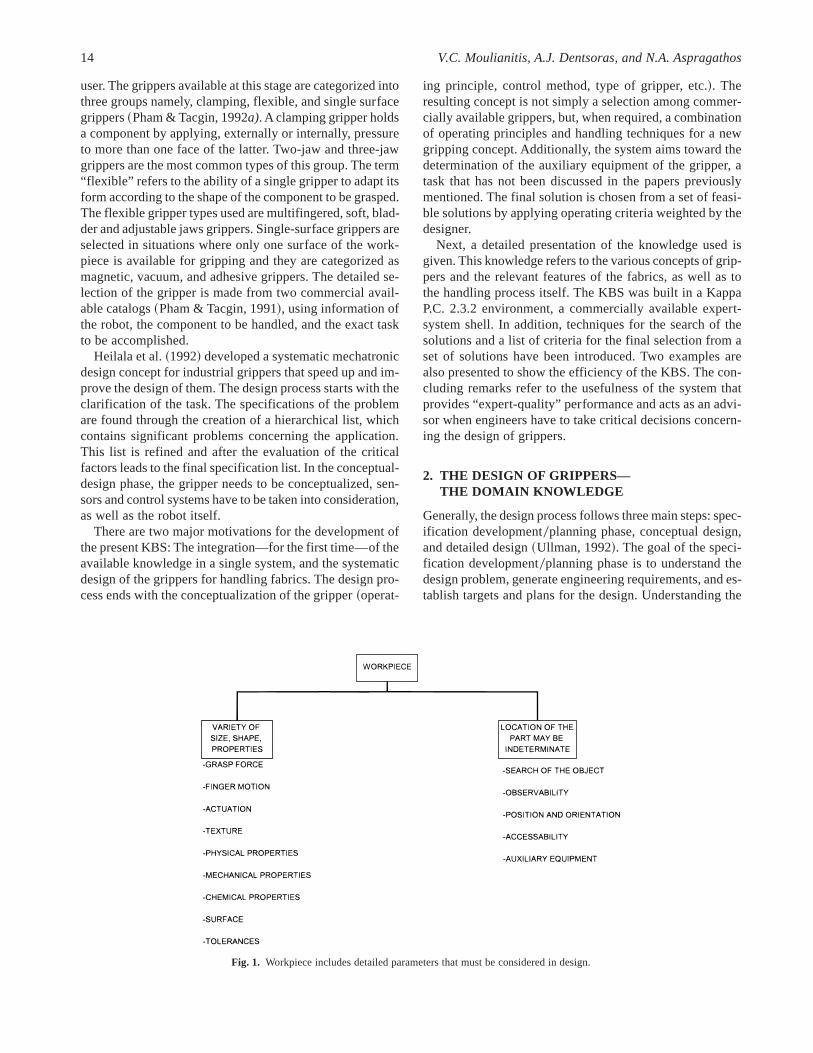
Fig. 1. Workpiece includes detailed parameters that must be considered in design.
14 V.C. Moulianitis, A.J. Dentsoras, and N.A. Aspragathos

design problem is not an easy task because most design prob-lems are ill-defined. When this task is accomplished, then aplan for the next phases of the design process must be es-tablished. Often, the development of the specifications willdetermine how the design problem can be decomposed intosmaller subproblems. The results of the specification devel-opment phase are used to generate and evaluate conceptsfor the product in conceptual design phase. The require-ments of the task that the product must accomplish serve asa basis for developing a functional model of the design,which leads to the generation of concepts from functions.Functional decomposition may occur, which leads the prob-lem in a more manageable form. The concepts that are gen-erated also have to be evaluated for their feasibility, orcompared to choose the best one. After the concepts havebeen generated and evaluated, the best is further processedto produce a final design.
The design process of grippers for handling fabrics fol-lows the same steps. For the KBS under consideration, focusis given to the first two steps of the design process. In thefirst step, the essential specifications are stated that have tobe fulfilled to obtain the desired operation. One way to sys-tematically search for the specifications is to create a hier-archical list of all the significant problems concerning theapplication~Heilala et al., 1992!. When all the potential prob-lems are listed, as a result of the evaluation of the criticalfactors, the refinement of final specification list for prelim-inary design is completed. The clarification of the problemis described in terms of the workpiece, the handling pro-cess, and the gripper itself. In Figures 1–3, details are givenconcerning the attributes of these factors. This problemhierarchy belongs to a general mechatronic approach fordesigning grippers. Some necessary modifications must be
made to the general approach due to the nature of the taskthat grippers perform~for example, radiation is not takeninto consideration!.
Because design of grippers is a relatively new design field,and there are not many working robotic cells for flexiblematerials, it was proved difficult to find experts in the field.Therefore, the knowledge used to build the present KBS wasacquired mostly from papers and handbooks. Additionally,the available literature was searched to find as much as pos-sible information about the design and manufacturing ofgrippers.
2.1. Knowledge about fabrics
The workpiece is the most important factor for the gripperdesign. It affects the structure and the function of the grip-per. The particular size, shape, and mass of the workpiecedetermine the final solution. There are, however, cases wherethe position and orientation of the workpiece are uncertainand, as a consequence, the determination of the final solu-tion becomes a difficult task.
Fabric specifications can be categorized into two groups:properties and characteristics. A property is a static physi-cal dimension and, a characteristic is the reaction of a fabricwhen a force is imposed upon it. The properties and char-acteristics of the fabrics are shown in Table 1, according toSolinger~1988! and Hudson~1988!. Elongation, elasticity,and shrinkage are examples of characteristics, but weight isa property of fabrics. The properties, the hand, and the util-ity characteristics are more useful for the design of the grip-pers than the style, durability, and product productioncharacteristics that mainly correspond to the apparel pro-ducers. Some of them are general and some are specific for
Fig. 2. Process includes detailed parameters that mustbe considered in design.
System for the conceptual design of grippers 15

particular grippers. For example, porosity is a vital factorwhen pin grippers are used because they may damage del-icate fabrics. When vision sensors are used the color of thefabric has to be taken into consideration.
2.2. Knowledge of the handling process
The type of handling process determines the design param-eters to be considered. Formally, it is expressed through thetask to be implemented and the environment within whichthe task takes place. Both the task and the environment areconsidered as external design parameters.
Dlaboha~1981a, b) stated that apparel plants may benefitfrom the use of robots in a variety of operations, such as
destacking, folding, die cutting etc. All the operations canbe further divided in more simple subtasks, namely:
• separation;
• picking;
• placing;
• applying tension; and
• assembling~for example the superposition of twopanels!.
For example, a sewing process includes an assembly taskand an applying tension task. In some cases, environment isa vital factor. Dust is undesirable in grippers with adhe-sives. Relative humidity is desirable in freezing grippers andaffects the electrical properties of the material. Vibrationsin the task of destacking releases the clinging edges of thematerials.
2.3. Knowledge about grippers
The gripper, which is the design goal, presents some oper-ational and structural attributes and includes mechanical andelectronic parts. Usually, grippers cooperate with auxiliaryequipment, which has to be specified, too.
Figure 4 illustrates the main handling techniques, whichare divided into the following three classes~Taylor, 1995!:
1. Mechanical surface, where the material is clamped orpinched between gripper finger to give high frictionalholding forces.
2. Intrusive, where pins are fed into the surface or bodyof the material and then moved to lock it into place.
3. Surface attraction, including the use of adhesives0vacuum.
Fig. 3. Characteristics and parts of gripper.
Table 1. Properties of fabrics
Properties
Fiber or filament: Type, size, length.Yarn: Diameter, twist, weight or size count, fiber content for mixed yarns,
ply.Weight: Ounces per square yard or yards per pound.Thickness: Vertical depth.Fabric structure: Woven fabrics; weave type, warp and filling yarn count
per linear inch. Knitted fabrics; knit type, wale, and course count perlinear inch.
Nonfibrous matter: Residual processing chemicals remaining in the fabric.Percentage of weight per total fabric weight.
Finishes: Chemicals and mechanical effects applied to the woven fabric toyield or enhance style durability, and0or utility values.
Fabric width: The length of the filling or course.Color: hue, value, and intensity.Fabric density: Weight per unit of volume.Surface contour: The geometric dimension of the surface plane.
16 V.C. Moulianitis, A.J. Dentsoras, and N.A. Aspragathos

It is obvious that the choice of one of those techniquesdepends on some properties of the material and its location.
Grippers can be categorized, also, by considered theiroperating principles. These categories are:
1. Pinching grippers~Monkman, 1993!.
2. Clamping grippers~Eiichi et al., 1989; Karakereziset al., 1994a, 1994b; Karakerezis, Doulgeri, Rizzi,et al., 1994; Karakerezis, Ippolito, et al., 1994; Para-schidis et al., 1995!.
3. Air-jets ~Kemp et al., 1986!.
4. Pin grippers~Parker et al., 1983!.
5. Brush grippers~Velcro!.
6. Vacuum0pneumatic grippers~Parker et al., 1983; Kol-luru et al., 1995!.
7. Electrostatic0magnetic grippers~Monkman, 1995;Monkman et al., 1989!.
8. Adhesive grippers~Parker et al., 1983; Monkman &Shimmin, 1991a, 1991b).
9. Freezing grippers.
The difference between these two classifications is thatthe first is based upon the way that the gripper approachesthe fabric and the second one by the working principle ofthe gripper. The~1!–~3! operational principles, called im-pactive, are used in the mechanical surface technique. The~4!–~5! operational principles, called ingressive, are usedin the intrusive technique. The~6!–~9! operational princi-ples, called astrictive~6–7! and contigutive~8–9! are usedin the surface attraction technique.
According to Taylor~1994!, the main factors to be con-sidered, in addition to weight, are:
• Impactive: Fabric bending stiffness, friction betweengripper, and fabric surface.
• Ingressive: Fabric stiffness, possible damage to deli-cate materials.
• Astrictive: Fabric molecular structure, surface texture,and flatness.
• Contigutive: Adhesive replenishment0cleaning, sec-ondary removal mechanism, heating0cooling cycles.
The control strategies that are used to handle fabrics canbe classified into five categories,~Gershon, 1993!:
• rigidization refers to any technique that temporarilytransforms the flexible material to a rigid object;
• model-based trajectory planning refers to the use of amathematical model of the flexible sheet, its mechan-ical behavior, and the task, to plan off-line a suitablerobot motion that will perform the task successfully;
• feedback-control strategies refers to the dynamic useof a sensor signal in a control loop during the perfor-mance of a dynamic manipulation task;
• sensor-based strategy, which is a reactive sequence ofelementary sensor-driven motions that reduce uncer-tainty in the state of the sheet; and
• sensor-less strategy, which is a predetermined se-quence of elementary motions that are designed to re-duce bounded uncertainty without sensing the state ofthe fabric.
The correct presence of a fabric panel can be detected bya number of different sensing techniques, such as:
• optical: reflective0through infrared;
• mechanical: detect limit of jaw movements;
• air flow: detect pressure drop of air flow.
3. DEVELOPMENT OF A KBS FORTHE DESIGN OF GRIPPERS
3.1. Structure of the system
The representation of the design knowledge can be madeusing logic, semantic networks, object-oriented program-ming ~OOP!, production rules, or a combination of thesemethods~Winstanley, 1991!. For the present case, OOP waschosen for two reasons: The first one is that by using OOPthe rules of the inference engine are easily integrated withthe conventional methods. Conventional methods will beused, mainly, for calculations in a future module of the sys-tem that will perform detailed design. Second, the softwareused for the implementation of the KBS is object-oriented.
Five classes were used to represent the knowledge in thesystem. Each class contains characteristic slots, such us op-erating principles of the gripper, control strategy, etc. Theclasses and the slots are shown in Table 3. The slots for Grip-per and Control are taken from Section 2.3. The most infor-mative attributes for the Material, according to Taylor~1994!,are taken from Tables 1 and 2. In addition, the environmen-
Fig. 4. Gripper techniques.
System for the conceptual design of grippers 17

tal factors that affect the design of grippers and taken intoconsideration are shown in Table 3.
Six rule sets were used for obtaining feasible solutions.The number in parentheses show the number of rules in thecorresponding rule set. These sets are:
1. Rules for the operating principle of grippers~41!, forexample,If Task is Placing And Status of Material is Free ThenGripper Operating Principle is Adhesive.
2. Rules that represent the design constraints~8!, for ex-ample,If Porosity of material is more than 30% Then Grip-per Operating Principle is Not Vacuum.
3. Rules for the type of the particular gripper~5!, for ex-ample,If Task is Separation And Gripper Operating Principleis Adhesive Then Type of Gripper is Plate.
4. Rules for the general characteristics of the gripper~6!,for example,If Gripper Operating Principle is Air-jet and Status offibers is clinged Then Power is High.
5. Rules for the control strategy~11!, for example,If Gripper Operating Principle is Vacuum and Task isPlacing Then Control Strategy is Rigidization.If Control Strategy is Sensor-Based Then Sensors areNeeded.
6. Rules for the auxiliary equipment~6!, for example,If Gripper Operating Principle is Velcro Then Auxil-iary Equipment is Remover.
3.2. Finding the best solution—Complexityof the search method
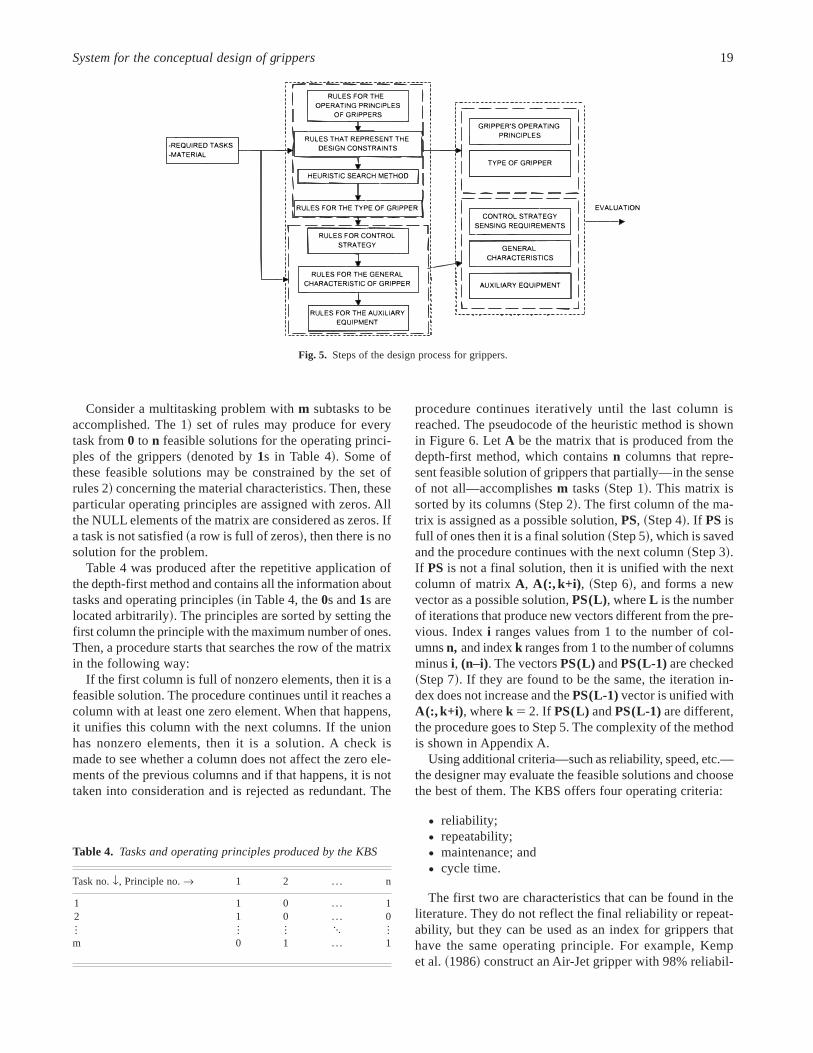
For most of the design problems, solutions are not knownapriori . The design is a data-driven process and the most usualinference mechanism is forward-chaining because it pro-duces more data while trying to find one or more solutionsto the problem under consideration. The steps of the pro-cess for designing grippers are shown in Figure 5. The rea-soning strategy is based upon a combination of a depth-firstsearch method and a heuristic one. After inputting the val-ues for the required tasks and material, depth-first searchmethod is fired with the first rule set for every task sepa-rately. The set of solutions of the first rule set, which rep-resents operating principles of the grippers, are inputted inthe second, which refines them and produces a set of feasi-ble solutions. A heuristic search method is fired, which ob-tains the set of final solutions of the problem. Next, the lastfour rule sets are sequentially fired for every final solutionand, then, produce the type of the grippers, the control strat-egy, and if sensing is needed, the general characteristics ofthe grippers and the auxiliary equipment.
Every design problem may have one or more feasible so-lutions. Below, a systematic process is presented that endswith the presentation of a single solution that satisfies allthe required specifications for the handling process. If thereis no such a operational principle, then a synthesis of theminimum number of operational principles is implementedthat leads to the simplest solution. This process is describedbelow:
Table 2. Characteristics of fabrics
Characteristics
Hand: Thickness compressibility, plane compressibility, elongation,elasticity, torsion, malleability, flexibility~self-flex, resistance flex,maintenance flex, reflex!, resilience, gravity drape, gravity sag, gravityelongation.
Visual: The changes in color when either the light or fabric is moved.Utility: Air permeability, heat transmission, light permeability, moisture
transmission, radioactivity transmission, water permeability, colorfastness, crease resistance, crease retention, crock resistance, dimensionalstability, felting, fusing, mildew resistance, moisture absorption, moistureretention, pilling, scorching, soiling, shrinkage, static electricity, yarnslippage.
Durability: Abrasive strength, bursting strength, corrosive strength, drycleaning durability, fire resistance, launderability, moth resistance,radiation absorption strength, tearing strength, tensile strength, yarnseverance.
Product production working: Coefficient of friction, Sewed seam strength,sewed seam slippage, sewing distortions, yarn severage, bondabilitystrength, die moldability, pressing moldability.
Table 3. Classes and slots
Class Slots Values
Gripper Operating Principle Freezing, clamp, velcro,pin, pinch, adhesive,electroadhesive,vacuum, airjet
Power High, medium, lowSetup Initial, readjustments
Control Strategy Sensor-based, sensor-less,feedback, rigidization,model-based
Sensing True, FalseMaterial Density Low, medium, high
Identity Cotton, velvet, linen, silk,lace, leather etc.
Porosity 0–100%Molecular Weight Low, medium, highStatus Free, free from the edge,
free from aboveSurface Rough, smoothTexture Woven, knittedThickness 0–5 mmWeight Low, medium, high
Gripping process Task Separation, apply tension,realizing, picking,assembly, placing
Environment Dust True, FalseTemperature Low, medium, highR. H. 0–100%
18 V.C. Moulianitis, A.J. Dentsoras, and N.A. Aspragathos
Consider a multitasking problem withm subtasks to beaccomplished. The 1! set of rules may produce for everytask from0 to n feasible solutions for the operating princi-ples of the grippers~denoted by1s in Table 4!. Some ofthese feasible solutions may be constrained by the set ofrules 2! concerning the material characteristics. Then, theseparticular operating principles are assigned with zeros. Allthe NULL elements of the matrix are considered as zeros. Ifa task is not satisfied~a row is full of zeros!, then there is nosolution for the problem.
Table 4 was produced after the repetitive application ofthe depth-first method and contains all the information abouttasks and operating principles~in Table 4, the0s and1s arelocated arbitrarily!. The principles are sorted by setting thefirst column the principle with the maximum number of ones.Then, a procedure starts that searches the row of the matrixin the following way:
If the first column is full of nonzero elements, then it is afeasible solution. The procedure continues until it reaches acolumn with at least one zero element. When that happens,it unifies this column with the next columns. If the unionhas nonzero elements, then it is a solution. A check ismade to see whether a column does not affect the zero ele-ments of the previous columns and if that happens, it is nottaken into consideration and is rejected as redundant. The
procedure continues iteratively until the last column isreached. The pseudocode of the heuristic method is shownin Figure 6. LetA be the matrix that is produced from thedepth-first method, which containsn columns that repre-sent feasible solution of grippers that partially—in the senseof not all—accomplishesm tasks~Step 1!. This matrix issorted by its columns~Step 2!. The first column of the ma-trix is assigned as a possible solution,PS, ~Step 4!. If PS isfull of ones then it is a final solution~Step 5!, which is savedand the procedure continues with the next column~Step 3!.If PS is not a final solution, then it is unified with the nextcolumn of matrixA, A(:, k+i) , ~Step 6!, and forms a newvector as a possible solution,PS(L), whereL is the numberof iterations that produce new vectors different from the pre-vious. Indexi ranges values from 1 to the number of col-umnsn, and indexk ranges from 1 to the number of columnsminusi, (n–i). The vectorsPS(L) andPS(L-1)are checked~Step 7!. If they are found to be the same, the iteration in-dex does not increase and thePS(L-1)vector is unified withA(:, k+i) , wherek 5 2. If PS(L) andPS(L-1)are different,the procedure goes to Step 5. The complexity of the methodis shown in Appendix A.
Using additional criteria—such as reliability, speed, etc.—the designer may evaluate the feasible solutions and choosethe best of them. The KBS offers four operating criteria:
• reliability;
• repeatability;
• maintenance; and
• cycle time.
The first two are characteristics that can be found in theliterature. They do not reflect the final reliability or repeat-ability, but they can be used as an index for grippers thathave the same operating principle. For example, Kempet al.~1986! construct an Air-Jet gripper with 98% reliabil-
Fig. 5. Steps of the design process for grippers.
Table 4. Tasks and operating principles produced by the KBS
Task no.f, Principle no.r 1 2 . . . n
1 1 0 . . . 12 1 0 . . . 0I I I L Im 0 1 . . . 1
System for the conceptual design of grippers 19

ity and Kolluru et al.~1995!, a vacuum gripper with morethan 99.6% reliability. The structures of these grippers aresimple, and the values of their repeatability is high~100%!.According to Heilala et al.~1992!, repeatability is an oper-ational factor of the gripper. Concerning the term mainte-nance, in the context of the present problem, it includes somespecial tasks, such as cleaning or changing specific parts ofthe gripper during its operation. For example, the adhesivegrippers need to clean their pad or change their adhesivetape after a specific number of cycles~Parker et al., 1983!.If maintenance is needed for a gripper, then a mark of 0.5 isgiven to it, otherwise this mark is 1.
Cycle time is defined as a fuzzy variable. The cycle timedepends absolutely upon the manufacturer and the imple-mented task and as a result, there are no established stan-dards for it. The contribution of the gripper in the cycle timeis scored according to this criterion. It is difficult to create asingle formula for the duration of all different tasks. It isconvenient to represent it using fuzzy logic. Knowing thefastest and the slowest operation~zero time!, the bounds forthe fuzzy system can be created. Three subsets~high, me-dium, and low! are then used together with three rules thatconclude about that characteristic of the gripper. The fuzzysystem is Sugeno-style and the rules have the form:
IF: cycle is . . .THEN: coefficient is . . . .
Cycle’s coefficient is a crisp number, formally named asa singleton. When the cycle time is high, the coefficient islow. When the cycle time is low, the coefficient is high, andwhen it is medium, the coefficient is medium. The relationsbetween the fuzzy sets and the singletons are shown inTable 5. Verification of this fuzzy system was made usingthe MATLAB ~Gulley & Roger Jang, 1995!. The member-ship functions for the cycle time is shown in Figure 7a andthe obtained output surface is illustrated in Figure 7b.
When the solution contains more than one operation prin-ciples, then the reliability, repeatability and maintenance fac-tors is the product of each operation principle factor. Forthe cycle time, all the consequences of the rules of all theoperating principles are fused and defuzzified~Yen &Pfluger, 1995!.
The best solution, according to the four criteria, is ob-tained by weights that are defined by the designer. The setof solutions is represented by a set of degrees and the solu-tion that has the higher degree is the best. These degrees aregiven by the formula:
degree5( wi fi
( wi
,
wherewi is the weight of thei th criterion andfi is the factorthat corresponds to thei th criterion of the particular gripper.
4. EXAMPLES
Below, two examples are given. The first one refers to asimple task, while the second refers to a complicated onethat, however, can be divided into simple tasks.
Fig. 6. Pseudocode of the heuristic search method.
Table 5. Relations between the fuzzy sets and the singletons
Cycle Coefficient
High 0.3Medium 0.6Low 1
20 V.C. Moulianitis, A.J. Dentsoras, and N.A. Aspragathos

4.1. Simple task
Until and unless single-layer cloth-cutting becomes practi-cal and economical, fabric will continue to be die- or knife-cut from multiple layers. Consequently, the most importanttask in any form of automated textile fabric handling is theremoval of a single ply from a stack of the same. This firstexample refers to design of a gripper that will perform thisoperation. Assume that the inputs in the KBS are~seeFig. 8!:
Required Task: Separation
Status of Material: Free~free from above and free fromthe edge!.
The first rule set produces eight operating principlesnamely, electroadhesive, adhesive, pinch, clamp, air jet, pin,vacuum, and freezing. This list is inputted to the second rulelist, which represent the design constraints, and contains in-formation about the material and the operating principles.The designer, now, is asked to input more data. Assume thatdata concerning the material are:
Identity: Cotton;
Thickness: 0.3 mm;
Porosity: 20%;
Surface: Smooth;
Density: High;
Molecular weight: Medium;
Weight: High;
Texture: Knitted;
Status of fibers: Clinged; and
Environment: Dust.
The KBS outputs six feasible solutions with the follow-ing operating principles:
1. Pin;
2. Pinch;
3. Vacuum;
4. Freezing;
5. Air Jet; and
6. Adhesive.
Every type of adhesive gripper can be used. For everyelement of this list, the control strategy, the sensing require-ments, and the auxiliary equipment are determined. The re-
Fig. 7. Membership functions of cycle time~a!. Output surface~b!.
Fig. 8. Initial inputs in the KBS.
System for the conceptual design of grippers 21

sults can be verified through the works of Kemp et al.~1986!and Parker et al.~1983!. An electrostatic gripper could notprovide enough force to overcome the gravitational forcesof a high-weighted material and knitted texture reduces theholding forces~Monkman et al., 1989!. In addition, no waywas found to separate a piece of material with thickness ap-proximately 0.3 mm with a clamp gripper~Eiichi et al.,1989!. Concerning the control strategy, verification can bemade through the work of Gershon~1993!.
The best solution can be found by applying combinationof the four criteria mentioned in the previous paragraph. Theevaluation was used twice for different weights and the re-sults are shown in Figure 9. The weights that correspond tothe results of Figure 9a are:
• Maintenance: 0.6;
• Reliability: 0.9;
• Repeatability: 0.7; and
• Cycle time: 0.8.
The weights that correspond to the results of Figure 9b are:
• Maintenance: 1;
• Reliability: 0.3;
• Repeatability: 0.8; and
• Cycle time: 0.7.
The best solution, which is based in the pin operating prin-ciple, is shown in Figure 10. The simple structure of the pin
Fig. 9. Evaluation degree of the solutions.
Fig. 10. Final solution of the KBS.
22 V.C. Moulianitis, A.J. Dentsoras, and N.A. Aspragathos
gripper allows use of the simplest control strategy, rigidiza-tion, which does not need any sensors. In addition, no aux-iliary equipment is needed.
4.2. Complex tasks
Sewing is a complex task and requires a number of tasks tobe fulfilled by a gripper. For example, the gripper must stacka single pocket panel on the top of a larger shirt front paneland then, if the sewing operation is not automated, to applytension to it to be sewed. The second example is the designof a gripper, which will perform all these tasks:
Required Task: Assembly
Apply tension
The first rule set produces one solution for the first task,namely, clamp, and two solutions for the second~vacuumand adhesive!.
The designer inputs the following data:
Status of material: Free~free from above and free fromthe edge!.
Identity: Cotton.
Thickness: 0.4 mm.
Porosity: 40%.
Surface: Smooth.
Density: High.
Molecular weight: High.
Weight: High.
Texture: Knitted.
Status of fibers: Free.
Environment: Dust.
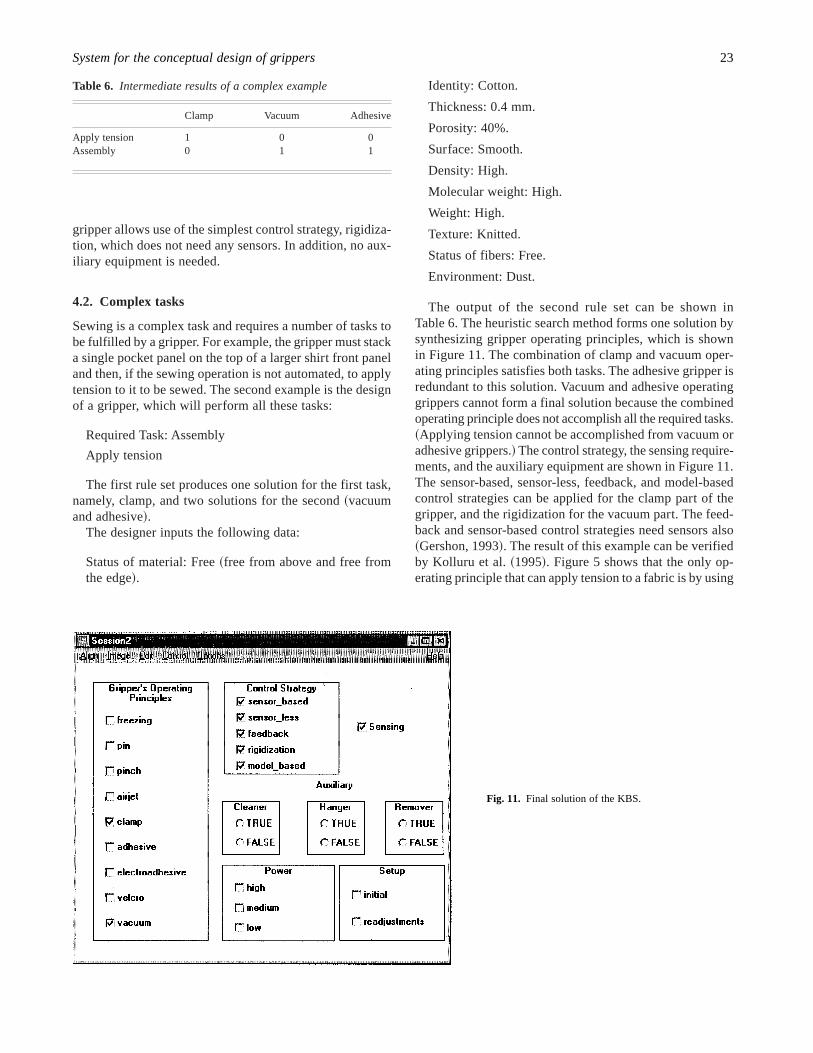
The output of the second rule set can be shown inTable 6. The heuristic search method forms one solution bysynthesizing gripper operating principles, which is shownin Figure 11. The combination of clamp and vacuum oper-ating principles satisfies both tasks. The adhesive gripper isredundant to this solution. Vacuum and adhesive operatinggrippers cannot form a final solution because the combinedoperating principle does not accomplish all the required tasks.~Applying tension cannot be accomplished from vacuum oradhesive grippers.! The control strategy, the sensing require-ments, and the auxiliary equipment are shown in Figure 11.The sensor-based, sensor-less, feedback, and model-basedcontrol strategies can be applied for the clamp part of thegripper, and the rigidization for the vacuum part. The feed-back and sensor-based control strategies need sensors also~Gershon, 1993!. The result of this example can be verifiedby Kolluru et al.~1995!. Figure 5 shows that the only op-erating principle that can apply tension to a fabric is by using
Table 6. Intermediate results of a complex example
Clamp Vacuum Adhesive
Apply tension 1 0 0Assembly 0 1 1
Fig. 11. Final solution of the KBS.
System for the conceptual design of grippers 23

a clamp grippers. Kolluru et al.~1995! constructed a vac-uum gripper for positioning a piece of fabric in the top ofanother.
In this example, the solution is a multigripper, which asfar as it is known, does not exist commercially. So, an orig-inal conceptual design was created. No evaluation is neededbecause the KBS produced only one solution.
5. CONCLUSION
In this paper, a KBS for the conceptual design of grippersfor handling fabrics is presented. The designed gripper canhandle materials, like paper or polymerics, with their thirddimension being small when compared with the other two.The knowledge used was collected by a relatively large num-ber of papers. This knowledge, in terms of gripper, mate-rial, and handling process was classified using differentapproaches and filtered out because there are conflictingopinions in the current literature.
Through the KBS, it is the first time that conceptual de-sign of grippers for handling fabrics is implemented. Theexisting KBS can achieve only selection of the operatingprinciple of the gripper or choose a gripper from a list ofcommercially available grippers, but they cannot concludeabout the control strategy, the sensing requirements, and theauxiliary equipment of the gripper. The present KBS con-tributes toward this direction and, additionally, it contrib-utes to the conceptual phase of design because it generatesnew ideas by applying a combination of existing ones. Theheuristic search method can be used in multiple hypothesesproblems, when the solution can be a combination of fea-sible conclusions. It produces the best solution according tofour criteria. The KBS developed can be used as an assis-tance tool in environments where no experts exist or as anadvisor when expert engineers have to make critical deci-sions concerning gripper design.
ACKNOWLEDGMENTS
This research is a part of work for the project funded by the EUin the INCO-COPERNICUS program: INCO-COP 9604438,“HOMER—Handling of nonrigid materials with robots.”
REFERENCES
Aho, A.V., Hopcroft, J.E., & Ullman, J.D.~1974!. The design and analysisof computer algorithms. Addison-Wesley, Reading, MA.
Dlaboha, I.~1981a). Are robots part of the future at apparel plants?Ap-parel World 27, 19–22.
Dlaboha, I.~1981b). Robotics and apparel industries cooperate in devel-oping apparel robots.Apparel World 27, 23–25.
Dym, C.L. ~1994!. Engineering design: A synthesis of views. CambridgeUniversity Press, New York.
Eiichi, O., Hidehiko, O., Hitoshi, A., & Noburu, A.~1989!. Robot handwith a sensor for cloth handling.Journal of the Textile Machinery So-ciety of Japan 37, 14–24.
Gershon, D.~1993!. Strategies for robotic handling of flexible sheet ma-terial. Mechatronics 3, 611–623.
Green, M.~1992!. Conceptions and misconceptions of knowledge aideddesign.Knowledge-Based Systems 10, 1–24.
Gulley, N., & Roger Jang, J.-S.~1995!. Fuzzy logic toolbox for use withMATLAB. The MathWorks Inc., U S A, Boston, MA.
Heilala, J., Ropponen, T., & Airila, M.~1992!. Mechatronic design for in-dustrial grippers.Mechatronics 2, 239–255.
Hudson, P.B.~1988!. Guide to apparel manufacturing. MEDIApparel Inc.,Greensboro, NC.
Karakerezis, A., Doulgeri, Z., & Petridis, V.~1994a). A robotic grippingsystem with consideration of grasping flat non rigid materials.IECONProceedings (Industrial Electronics Conference), 936–941.
Karakerezis, A., Doulgeri, Z., & Petridis, V.~1994b). A gripper for han-dling flat non-rigid materials.Automation and Robotics in Construc-tion IX, 593–601.
Karakerezis, A., Doulgeri, Z., Rizzi, C., Petridis, V., & Ippolito, M.~1994!.Handling of flat non rigid materials with consideration of robotic grip-ping systems.Fifth World Conference on Robotics Research, MS94-234, 1–15.
Karakerezis, A., Ippolito, M., Doulgeri, Z., Rizzi, C., Cugini, C., & Petri-dis, V. ~1994!. Robotic handling for flat nonrigid materials.Proc. IEEEInt. Conf. Systems, Man and Cybernetics, 937–946.
Kemp, D.R., Taylor, G.E., Taylor, P.M., & Pugh, A.~1986!. A sensory grip-per for handling textiles.Robot Grippers 2, 155–164.
Kolluru, R., Valavanis, K.P., Steward, A., & Sonnier, M.J.~1995!. A flat-surface robotic gripper for handling limp material.IEEE Robotics andAutomation Magazine, 19–26.
Monkman, G.J.~1993!. Automated handling of packaging materials.In-dustrial Robot 20, 16–19.
Monkman, G.J.~1995!. Robot grippers for use with fibrous materials.TheInternational Journal of Robotics Research 14, 144–151.
Monkman, G.J., & Shimmin, C.~1991a). Use of permanently pressure-sensitive chemical adhesives in robot gripping devices.InternationalJournal of Clothing Science and Technology 3, 6–11.
Monkman, G.J., & Shimmin, C.~1991b). Permatack adhesives for robotgrippers.Assembly Automation 11, 17–19.
Monkman, G.J., Taylor, P.M., & Farnworth, G.J.~1989!. Principles of elec-troadhesion in clothing robotics.International Journal of Clothing Sci.Technol. 1, 14–20.
Paraschidis, K., Fahantidis, N., Vassiliadis, V., Petridis, V., Doulgeri, Z.,Petrou, L., & Hasapis, G.~1995!. A robotic system for handling textilematerials.IEEE Int. Conf. Robotics and Automation, 1769–1774.
Parker, J.K., Dubey, R., Paul, F.W., & Becker, R.J.~1983!. Robotic fabrichandling for automating garment manufacturing.Journal of Engineer-ing for Industry 105, 21–26.
Pham, D.T., & Tacgin, E.~1991!. DBGRIP: A learning expert system fordetailed selection of robot grippers.Int. J. Prod. Res. 29, 1549–1563.
Pham, D.T., & Tacgin, E.~1992a). GRIPPEX: A hybrid expert system forselecting robot gripper types.Int. J. Mach. Tools. Manufact. 32, 349–360.
Pham, D.T., & Tacgin, E.~1992b). A expert system for selection of robotgrippers.Expert Systems with Application 5, 289–300.
Solinger, J.~1988!. Apparel manufacturing handbook. Bobbin Media Corp.,Columbia, NC, USA.
Taylor, P.M.~1994!. A toolbox of garment handling techniques.IEE Col-loquium on Intelligent Automation for Processing Non-rigid Products,101–104, Savoy Place, England.
Taylor, P.M.~1995!. Presentation and gripping of flexible materials.As-sembly Automation 15, 33–35.
Ullman, D.G.~1992!. The mechanical design approach. McGraw-Hill Inc.,New York.
Winstanley, G.~1991!. Artificial intelligence in engineering. John Wiley& Sons Ltd., New York.
Yen, J., & Pfluger, N.~1995!. A fuzzy logic based extension to Payton andRosenblatt’s command fusion method for mobile robot navigation,IEEETransactions on Systems, Man, and Cybernetics 25, 971–978.
APPENDIX A
To find the complexity of the method, considerm tasks thatare accomplished partially byn grippers concepts. For ev-ery task, a depth first algorithm is executed to specify thegrippers’ concepts that accomplish the specific task. Each
24 V.C. Moulianitis, A.J. Dentsoras, and N.A. Aspragathos

depth-first algorithm needsO~max~n1,n2!! time, wheren1 5 number of the vertex of the graph andn2 5 numberof the edges. In this case the total time isO~2m!. For thesorting process, the quicksort algorithm is used with knowncomplexityO~n{log n! ~Aho et al., 1974!. In the last part ofthe algorithm, two processes take place: union and rejec-tion ~if needed!. In the worst case, alln solutions will be
unified. The process of union needsOSn{~n 2 1!
2 D time. If
the first m2 n 2 1 feasible solutions are redundant, then
OS ~n 2 m2 1!{~n 2 m!
2 D time is needed for the rejections.
V.C. Moulianitis received a Mechanical Engineering de-gree in 1996 at the Department of Mechanical Engineeringand Aeronautics, University of Patras in Greece, where heis currently a Ph.D. candidate. His main interest is the useof AI techniques in mechanical engineering design.
A. J. Dentsorasis an Assistant Professor at the Departmentof Mechanical Engineering and Aeronautics, University ofPatras, Greece since 1993. His main research interests are
design theory, the representation and handling of determin-istic and fuzzy knowledge in well-defined design problems,and the development of new AI-based techniques for thedesign of belt conveyors. He has published several papersin various international journals relevant to the above top-ics. He is currently investigating a new approach for thehandling of constraint violations in well-defined designproblems.
N.A. Aspragathosis an Associate Professor in the Depart-ment of Mechanical Engineering and Aeronautics, Univer-sity of Patras, Greece. His current main research interestsare robotics, industrial automation, CAD0CAM, and simu-lation. He has developed algorithms for robot path planningand trajectory generation using genetic algorithms and neu-ral nets, robot assembly strategies, and dynamic simulationof robots. He worked on the development of a shoe CADsystem, a robot simulator, and a system for simulation oftextile and apparel production lines. He has published about50 papers in journals and conference proceedings. He is areviewer for several journals and a member of the editorialboard ofMechatronics Journal. He is currently involved inresearch projects funded in Greek and European Unionsources.
System for the conceptual design of grippers 25