A knowledge base for indexing and retrieving disassembly plans
18
Journal of Intelligent Manufacturing 12, 77–94, 2001 # 2001 Kluwer Academic Publishers. Manufactured in The Netherlands. A knowledge base for indexing and retrieving disassembly plans LI PAN and I. ZEID* Department of Mechanical, Industrial, and Manufacturing Engineering, Northeastern University, Boston, MA 02115–5000, USA Received August 1999 and accepted April 2000 Disassembly has become an important issue recently, as people begin to be concerned about the environment and natural resources. Many methodologies have been used to tackle disassembly problems. Design for disassembly (DFD) and planning for disassembly (PFD) are the two main approaches to address such problems. The focus of this paper is on PFD. To assist planners to solve PFD problems, a system must have some heuristics and domain specific knowledge, which is related to the representation of the disassembly knowledge. In previous work, the authors proposed to use EMOPs (eposodic memory organization packet) for the knowledge representation of the PFD plan. This paper presents the implementation of the EMOP memory model. The model has been implemented in C . Examples are presented to demonstrate the capabilities of the memory model. Keywords: Disassembly, design for disassembly, planning for disassembly, case-based reasoning, EMOP memory model, knowledge representation 1. Introduction Traditional manufacturing systems consist only of a one way process, i.e., using different parts to assemble products. When the products reach their life expectancy, or are replaced by new products, they are discarded and sent to landfills. Research on disassembly has evolved as people begin to be concerned about the capacity of the environment to sustain such activities. Government is taking steps to limit such activities by increasing disposal taxes, setting regulations to force manufacturers to take back their products at the end of their life cycle, and reuse their materials. These changes lead to two-way operations, i.e., assembly and disassembly, for the new manufacturing systems. Disassembly is the process of systematic removal of desirable constituent parts from an assembly. The disassembly process must be cost efficient, otherwise the products will be discarded instead of disas- sembled. Much research on disassembly has been done in order to improve the efficiency and to reduce its cost. These research activities can be roughly divided into two branches, viz., design for dis- assembly (DFD) and planning for disassembly (PFD). Design for disassembly is an approach that integrates all life-cycle phases (development, produc- tion, distribution, usage, and disposal or recycling) into a very early step of conceptual product design through the detailed design step. The designer must consider issues from product structure to material choosing, from minimizing waste to manufacturing processes (Boothroyd and Alting, 1992). Unlike traditional design, DFD looks closely at the design from a disassembly point of view. For example, if two materials can be used in the design based on stress calculations, but one is recyclable and the other is not, the designer should choose the recyclable material. While designing parts, designers should also create parts that lend themselves to non-destructive *Correspondence author.
Transcript of A knowledge base for indexing and retrieving disassembly plans
Journal of Intelligent Manufacturing 12, 77±94, 2001
# 2001 Kluwer Academic Publishers. Manufactured in The Netherlands.
A knowledge base for indexing and retrieving
disassembly plans
L I PA N and I . Z E I D *
Department of Mechanical, Industrial, and Manufacturing Engineering, Northeastern University,Boston, MA 02115±5000, USA
Received August 1999 and accepted April 2000
Disassembly has become an important issue recently, as people begin to be concerned about the
environment and natural resources. Many methodologies have been used to tackle disassembly
problems. Design for disassembly (DFD) and planning for disassembly (PFD) are the two main
approaches to address such problems. The focus of this paper is on PFD. To assist planners to solve
PFD problems, a system must have some heuristics and domain speci®c knowledge, which is related to
the representation of the disassembly knowledge. In previous work, the authors proposed to use
EMOPs (eposodic memory organization packet) for the knowledge representation of the PFD plan.
This paper presents the implementation of the EMOP memory model. The model has been
implemented in C� � . Examples are presented to demonstrate the capabilities of the memory model.
Keywords: Disassembly, design for disassembly, planning for disassembly, case-based reasoning,
EMOP memory model, knowledge representation
1. Introduction
Traditional manufacturing systems consist only of a
one way process, i.e., using different parts to assemble
products. When the products reach their life
expectancy, or are replaced by new products, they
are discarded and sent to land®lls. Research on
disassembly has evolved as people begin to be
concerned about the capacity of the environment to
sustain such activities. Government is taking steps to
limit such activities by increasing disposal taxes,
setting regulations to force manufacturers to take back
their products at the end of their life cycle, and reuse
their materials. These changes lead to two-way
operations, i.e., assembly and disassembly, for the
new manufacturing systems.
Disassembly is the process of systematic removal
of desirable constituent parts from an assembly. The
disassembly process must be cost ef®cient, otherwise
the products will be discarded instead of disas-
sembled. Much research on disassembly has been
done in order to improve the ef®ciency and to reduce
its cost. These research activities can be roughly
divided into two branches, viz., design for dis-
assembly (DFD) and planning for disassembly
(PFD). Design for disassembly is an approach that
integrates all life-cycle phases (development, produc-
tion, distribution, usage, and disposal or recycling)
into a very early step of conceptual product design
through the detailed design step. The designer must
consider issues from product structure to material
choosing, from minimizing waste to manufacturing
processes (Boothroyd and Alting, 1992). Unlike
traditional design, DFD looks closely at the design
from a disassembly point of view. For example, if two
materials can be used in the design based on stress
calculations, but one is recyclable and the other is not,
the designer should choose the recyclable material.
While designing parts, designers should also create
parts that lend themselves to non-destructive*Correspondence author.

disassembly instead of destructive one. This approach
will ease the work of disassembling products when
products meet their end-of-life. However, many
currently recycled products were designed more
than a decade ago. There were no considerations
during the design phase of the products about an easy,
low cost disassembly process. How to ef®ciently
disassemble these products needs the knowledge of
planning for disassembly (PFD). Nonetheless, these
products without DFD are not the only bene®ciaries of
PFD knowledge. PFD can also be applied to the
products designed with the concept of DFD in mind.
Whether the product is designed with DFD knowledge
or not, it still need to have disassembly plan. The only
different between these two types of product is that
one is easy to plan for disassembly, and the other is not
so easy to plan for disassembly.
Planning for disassembly identi®es ef®cient
sequences to disassemble products. A PFD problem
can be de®ned as: Given a product structure, a
disassembly goal, and a set of disassembly con-
straints, ®nd a plan to successfully disassembly the
product (Zeid et al., 1997). The disassembly plan has
to satisfy these goals and constraints. The solution (or
disassembly plan) depends on how well the problem is
de®ned according to the goals, constraints and product
structure. The solution may require optimization and
improvements. Even if the problem is well de®ned,
there may still be multiple solutions to satisfy the
goals and constraints. This characteristic is de®ned as
open ended. As the problem is open ended, a few
iterations may be necessary to obtain the ®nal
optimized disassembly plan. Open endedness and
iterations are the two main characteristics of PFD
problem. This is partially related to the inherent nature
of the problem and partially due to the ¯exibility of
disassembly plans (Zeid et al., 1997).
The identi®cation of alternative solutions, and the
selection of the optimized one (based on quantitative
analysis) are perhaps the most important steps in
®nding a solution to a PFD problem. This issue is
related to knowledge reuse. In this area, much
research has been done by using case-based reasoning
(CBR) to solve the same class of new problems. The
episodic memory organization packet (EMOP)
(Kolodner, 1984) is the most pervasive memory
structure in CBR for knowledge expression. It has
been applied to mechanical design by Bardasz and
Zeid (1992). Zeid et al. (1997) also proposed to use
EMOP in disassembly planning. This paper is the
implementation of the proposal, which is to build a
memory model to save and retrieve the disassembly
plans.
2. Overview of disassembly research
Environmental issues and legislation have forced
more companies to adopt disassembly operations.
Several of automobile manufacturers have opened
dismantling plants. BMW has opened a dismantling
plant in Orlando, Florida (Grogan, 1994) and several
other plants in Europe. Volkswagen also has a
dismantling plant in Europe and will open more
(Corcoran, 1992). Other industries also use disas-
sembly operations, like the Dutch ®rm Coolrec b.v.
The company dismantles refrigerators with a yearly
processing capacity of about 50,000 units. It neu-
tralizes the Freon in a special degassing installation
and processes the other parts into environmentally
friendly pieces and easy to reuse materials (Penev and
DeRon, 1994). Other applications of disassembly can
be seen in almost every industry such as electronics,
defense and industrial equipment.
The research activities on PFD are relatively
limited and focus on disassembly sequences genera-
tion, strategies, simulation, and analysis. Penev and
deRon (1996) use the theory of graphs and the method
of dynamic programming to generate and evaluate the
feasibility of disassembly plans. They introduce ®ve
disassembly levels: service, disassembly, dismantling,
recycling, and disposal. By using graph theory, a
disassembly process is described. Dynamic program-
ming is used for the determination of an optimal
disassembly level and the corresponding process.
Johnson and Wang (1995) establish four criteria to
optimize the generation of the disassembly sequence
for material recovery: material compatibility, clus-
tering for disposal, concurrent disassembly
operations, and maximizing yield. A four-level
disassembly analysis methodology is developed,
from low level to high level: feasibility study, optimal
disassembly sequence generation, disassembly opti-
mization, and DFD guidelines. It is used to identify
and assess the cost-effective characteristics of
disassembly for the recovery of materials.
Yokota and Brough (1992) use a precedence graph
to express partial orders of disassembly. A hierarch-
ical object representation is introduced as the basis of
assembly/disassembly sequence planning. The con-
78 Pan and Zeid
tact relations between the surfaces of parts are
represented by leaves in the hierarchical object
representation. The hierarchical object representation
is implemented in Prolog.
Arai et al. (1995) introduce a part assemblability
veri®cation system by testing the product's disas-
semblability. They generate disassembly path of a
solid model using tree structural data whose nodes and
arcs denote con®gurations and possible motions of the
part, taking into account the contact constraints and
transitions between the components of the product.
Arai and Iwata (1993) develop a CAD system that
can assist designers in making a product assembly/
disassembly plan. Kinematics simulation is used to
construct the CAD system and select the best method
for the disassembly sequence.
Beasley and Martin (1993) focus their discussion of
disassembly sequences on the objects with only a
®nite number of unit cubes. Each disassembly step
consists of one or two linear motions of single parts.
They discuss globe geometric feasibility, which is
applied to determine if the movement of subassembly
by some ®nite amount in a speci®c direction is
possible. Woo (1991) discusses the generation of
sequences in 3D with geometrical, logical, and
dimensional considerations. With the generating of a
disassembly tree, an algorithm is developed to
compute disassembly sequences.
Gupta and his research team (Brennan et al., 1994;
Gupta and Taleb, 1994) focus on operation planning
issues and scheduling disassembly. Contrary to other
researchers, they think that the disassembly sequence
is not the exact opposite of the assembly sequence. In
Brennan et al. (1994), they address some disassembly
issues such as item segregation, reverse material ¯ow,
and item explosion. In Gupta and Taleb (1994), an
algorithm that reverses the MPR (material require-
ments planning) is developed for scheduling the
disassembly of those discrete-parts products char-
acterized by a well-de®ned product structure. But the
algorithm is not the reverse of the MRP algorithm,
although the objective of the disassembly case is the
reverse of the MRP. It is considerably more
complicated.
All of the above studies place emphasis on the cost
analysis and disassembly sequences generation for
geometric or product structure constraints. None of
these efforts addressed the issue of developing a
computational model to either automate disassembly
planning or to capture past disassembly knowledge for
PFD. Only in Zeid et al. (1997), did Zeid and Gupta
consider the issue. They use Anological Problem
Solving (APS) to assist planners to solve PFD
problems. The EMOP memory model is used to
represent and store PFD plans. At the end of Zeid etal. (1997), the important issues to be addressed are
discussed to get the full bene®t and power from
applying APS to solve PFD problems. Two of these
issues are: (1) What are the abstractions needed to
help in the planned description? (2) What taxonomy
of PFD characteristics should be used to create indices
to store/retrieve PFD plans? These indices are used to
create the memory model and later to traverse it.
These two issues will be addressed in this paper.
Considering the nature of the PFD problem (open
ended and iterative) and the previous research efforts,
it is obvious that the PFD knowledge is product
speci®c. The knowledge of disassembling a product
can be used for similar products. In order to use
previous knowledge, the following two questions
need to be considered: First, how to capture, save and
re-use previous disassembly experiences? Second,
how to develop adaptable PFD algorithms that can
``learn'' PFD (Zeid et al., 1997)
Two methods can be used to address these two
questions: PFD automation and PFD learning. In this
paper, we will use the PFD learning approach to
address the ®rst question above. Speci®cally, we
propose a memory model that uses disassembly
features (see Section 3) as indices to retrieve or
store disassembly plans from a knowledge base.
Using hash tables, the memory model can save a
speci®c disassembly sequence for one product into
®les, then store them in the knowledge base. The
disassembly sequences can be retrieved for later use.
3. Disassembly knowledge and hierarchy
The desired memory model of the proposed knowl-
edge base should be able to store and retrieve
disassembly plans properly. The features used to
index the memory model are critical to its successful
implementation. It is especially important that the
features are generic enough so the memory model is
domain independent and can be used in any kind of
product domain.
Disassembling a product is easy when the product
structure is given, and is dif®cult when the product
A knowledge base for indexing and retrieving disassembly plans 79

structure is unknown. Suppose that the structure of a
lamp is presented as shown in Fig. 1.
If the disassembly goal is to get the Lamp Vase,
according to the structure above, the disassembly
sequences should be: 1st, take off the Bottom Nut;
2nd, take out the Center Pipe, 3rd, take off the Lamp
Vase from the Lamp Base. If the disassembling goal is
to get the Socket with Switch on it, the disassembly
procedure may look like: 1st, take off the Socket
assembly by unscrewing the Terminal Screw; 2nd,
separate the Outer Shell and Insulating Sleeve from
the Socket assembly. Apparently, different disas-
sembly goals will generate different disassembly
plans: A disassembly plan describes the disassembly
sequence people should or have to know.
One of the factors that needed to be considered is
that disassembly plans may differ depending on the
selection of destructive or non-destructive operations.
So the memory model needs the ability to store two
different disassembly plans, one for reuse (non-
destructive operation), another for recycle (destruc-
tive operation). The term ``constraint'' is used in the
memory model implementation to identify these two
different disassembly plans.
In order to de®ne the common features used in the
memory model as indices, the structures of two
product families are analyzed below.
The ®rst product to be examined is an automobile.
There are some common features shared by different
cars, such as power system, exhaust system, electrical
system and so on. At the next level, an engine is made
up of pistons, cylinders, valves, crankcase, gears and
so on. A piston includes compression ring, oil ring,
wrist pin, connecting rod, and the piston itself. From
this analysis, a statement can be made that, in general,
a car is made of assemblies and parts, and assemblies
are composed of subassemblies and parts.
Subassemblies are usually made up of yet other
subassemblies and parts. Subassemblies may have
several levels (or layers) of subassemblies, but the last
level (or layer) of a subassembly is always made of
parts. A product structure tree can be shown as in Figs.
2±4.
The second product family to be examined is a
household fan. There are many kinds of fans, such as
window fans, ceiling fans, table fans and so on. But
most of the fans share the same structure, too. They
consist of motors, grills, blades, washers, switches and
so on. The motors have ®eld winding, stator, rotor,
and shaft. From the above analysis point of view, a
conclusion can be made that all fans are made of
assemblies and parts, and assemblies are composed of
parts. Similarly, a product tree for a window fan can
be shown as Figs. 5 and 6.
From the analysis of the two products, it can be
concluded that every product has assemblies and
parts. An assembly may have subassemblies and
parts; a subassembly may have further subassemblies
Fig. 1. Lamp structure tree.
80 Pan and Zeid

and parts. The same product family usually shares the
same structures. But different products usually have
different structures and a different disassembly
sequence may be needed. Sometimes, a subassembly
can be called as an assembly from a different point of
view. Assemblies and subassemblies are really over-
lapped in categorization. For the memory model
implementation, four levels have been de®ned. They
are product, assembly, component and parts. A
product level contains all artifacts that can be used
by the customer directly. An assembly level contains
artifacts that make up a product or an assembly. Since
there will be much more assemblies than products, it
is better to divide the assembly level into two levels
for a better memory model implementation. A
component level is de®ned as a level that contains
artifacts made up of all parts. A part level contains
artifacts that cannot be further disassembled. In this
paper, product's name, model, and type are used to
distinguish products. By using indices of product
name, type, model, assembly, component, part and
constraints, the disassembly plan can be stored in a
database, and the same indices are used to retrieve the
disassembly plans.
The common features for a product can be
generated as shown below considering the above
discussions:
Constraint: reuse or recycle
Name: Jeep
Type: two-stroke engine
Model: Grand Cherokee
Parent model: Grand Cherokee
Level: product
Similar features have been developed for an
assembly, a component, or a part. All these features
are listed in Table 1.
4. Disassembly knowledge representation
The above section has identi®ed the features and
hierarchies of products from a disassembly point of
view. The identi®cation of these features is crucial to
the successful representation of disassembly knowl-
edge. In this paper, we utilize an EMOP memory
model to represent the identi®ed disassembly knowl-
edge. The knowledge is represented in the model as
disassembly plans, one plan per product. Each plan is
a hierarchical free that represents the product structure
that can be traversed to generate disassembly plans.
The memory model design is based on the concept
that the current problem solving plan can bene®t from
the experience of past similar problem solving plans.
A successful memory model must retrieve and store
the disassembly plans ef®ciently and intelligently. An
episodic memory model (Shank and Adelson, 1977)
®ts well in this situation. The structure of the episodic
memory model is based on the theory that human
knowledge is accumulated from personal experiences.
EMOPs (Shank, 1982) are the basic operation
Fig. 3. Structure tree of an engineÐat the assembly level.
Fig. 2. Structure tree of a carÐat the product level.
A knowledge base for indexing and retrieving disassembly plans 81

elements of the episodic memory. EMOPs are indexed
in the memory by the features they describe. EMOPs
that store general information can be treated as nodes,
while EMOPs that store particular PFD plans can be
treated as leaves.
In designing the memory model for disassembly,
the most important issue to be addressed is the
de®nition of the mechanism for disassembly plan
retrieval, which will have an impact on the down-
stream tasks such as modi®cation, storing, and
removing. The disassembly plan retrieval issue is
concerned with knowledge base organization. Other
issues include retrieving speed, memory model
maintenance and computer memory requirement.
The proposed memory model has the following
characteristics: (1) The model is dynamic and will
grow bigger as disassembly plans are accumulated.
(2) The size of the memory model is hard to
predetermine. (3) Both the fast retrieval and the fast
storage are needed. (4) Occupy as less computer
memory space as possible. Considering all of these,
the memory model is organized in four parallel levels.
From top to down, they are product level, assembly
level, component level and part level. In each
level, the memory model is designed in a tree-like
structure.
The product level holds the product's disassembly
plans. The assembly level holds the disassembly plans
for an assembly and/or the disassembly plans for
disassembling an assembly from a product. The
component level holds the disassembly plans for
components and/or the disassembly plans for disas-
sembling a component from an assembly. And the part
level holds the disassembly plans for disassembling a
part from a component. Here we assume that a part is
a non-separated body.
It is common that a non-destructive disassembly
plan may differ from a destructive disassembly plan.
Taking the constraint feature into account, the
designed memory model actually consists of eight
categories, which are combinations of levels and
constraints. Figure 7 shows the structure of the EMOP
memory model that uses these eight categories. This
structure makes it possible for searching disassembly
plans using as fewer steps as possible. The searching
steps are reduced which in turn will reduce the access
time. Having eight categories increases the overhead
of the memory space, but it will be off set by easy
maintenance of the memory model and increasing
error tolerance of the system. For instance, if
``product-reuse'' category is destroyed, it will not
affect the ``product-recycle'' category and all other
categories. Only the ``product-reuse'' category needs
to be repaired. Dividing memory model into these
categories has following advantages:
* Interacting with a minimal search space,
increase the retrieving speed.
Fig. 4. Structure tree of a pistonÐat the subassembly level.
Fig. 5. Structure tree of a window fanÐat the product level.
Fig. 6. Structure tree of a shade-pole motor for a window fanÐat
the assembly level.
82 Pan and Zeid

* Providing a natural division of the knowledge
base for the designer.* Easy maintenance of the model.
Using an artifact's name, type, brand, and model as
indices for searching disassembly plan will be more
suitable to disassembly area. But knowing a product's
structure will be helpful to get a good similar
disassembly plan when no disassembly plan for a
particular artifact is available in memory model.
This memory model supports ®ve general opera-
tions. Under each general operation except for the
display operation, several speci®ed operations are
supported. The following lists these operations:
* Search for and retrieve a disassembly plan
± Search disassembly plan by features
± Search for a disassembly plan
± Search a disassembly plan to disassemble
an assembly from a product (a component
from an assembly, or a part from a
component)
± Search a disassembly plan by artifact
structure.* Update a disassembly plan
± Modify a disassembly plan
± Modify a disassembly plan to disassemble an
assembly from a product (a component from
an assembly, or a part from a component)* Add a new disassembly plan
± Add a new disassembly plan
Table 1. Index types
Product indices Assembly indices Component indices Part indices
Constraint Constraint Constraint Constraint
Level Level Level Level
Name Name Name Name
Type Type Type Type
Model Model Model Model
Parent model Parent model Parent model
Fig. 7. The EMOP memory model for PFD.
A knowledge base for indexing and retrieving disassembly plans 83

± Add a new disassembly plan to disassemble
an assembly from a product (a component
from an assembly, or a part from a
component)* Remove a disassembly plan
± Remove a disassembly plan
± Remove a disassembly plan to disassemble
an assembly from a product (a component
from an assembly, or a part from a
component)* Display all disassembly plans in a category.
5. Accessing the disassembly knowledge base
As has been described so far, we have developed a
disassembly knowledge base. The heart of this
knowledge base is its EMOP memory model.
Utilizing this model, we are able to store disassembly
plans for different products in the knowledge base.
The knowledge base has an index of all its plans. Each
plan is stored in a ®le. Disassembly designers and
planners should be able this knowledge base
effectively. In this context, they should be able to
store new disassembly plans in the knowledge base,
search for existing plans, retrieve a speci®c existing
plan, and/or delete existing plans. The role of storage
is to allow planners to input and add new disassembly
plans for new products, to the knowledge base. The
role of retrieval is to allow planners to pull out and use
an existing disassembly plan ( previously stored) from
the knowledge base. The role of search is to allow
planners to interrogate the knowledge base for plans
that planners my not be aware of. After a search is
complete, planners can retrieve any of the found
plans. The role of deletion is to allow planners to
remove unwanted existing plans from the knowledge
base.
Various algorithms have been developed and
implemented (see Section 6 below) to perform
storing, retrieving, searching, and deleting disas-
sembly plans. These algorithms are unique and new
because this is the ®rst time the EMOP memory model
has been applied to disassembly planning. Thus, there
are benchmarks to compare these new algorithms
against. However, we offer some performance
evaluations in the implementation section (Section 6
below) of this paper. Future enhancements of these
algorithms can be done after testing and evaluating
their performance long enough.
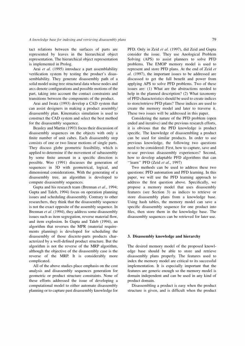
5.1. The storage algorithm
In the storing operation, the goal is to ®nd where a
disassembly plan should be added in the memory
model. When there is no index to match the feature
being added, a new index that corresponds to the new
feature is created. This index points to the disas-
sembly plan being stored. Otherwise, the algorithm
travels along the indices until it ®nds a matching one,
then stores the plan under this matching index.
To store a disassembly plan of a product, the
algorithm ®rst checks the product features. The
product's name is used as an index that differentiates
the current product from other products in the memory
model. The model of the current product is used as an
index too. The memory model can identify several
different product models under the same product
name. The product's type is used as a reference in the
search algorithm (see next section). After the memory
model gets the needed features, it will search to see if
the product's name exists. If the name does not exist,
the memory model will create a new EMOP. Under
this EMOP, the memory model will create a new
model node. The disassembly plan is stored under the
product's model. If the product name exists but the
model does not, the memory model creates a new
model node, and stores the disassembly plan under
this node. Otherwise, The memory model tells the
user that the disassembly plan already exists and
displays it. The storage algorithm ¯ow chart is shown
in Fig. 8.
5.2. The search and retrieval algorithm
The search mechanism is essential to the memory
model. It severs as an organizer to ®nd a disassembly
plan/similar disassembly plan for a certain goal, or to
®nd possible disassembly plan from a mechanical
artifact's structure. Since information of a mechanical
artifact's name, type, and model is easy to get, it is not
necessary to know the mechanical artifact's structure
to retrieve a disassembly plan from the memory
model. There are three different search results to
retrieve a disassembly plan from memory model
according to different situations.
The ®rst result is a successful search (exact match).
It occurs when there is a disassembly plan for certain
84 Pan and Zeid
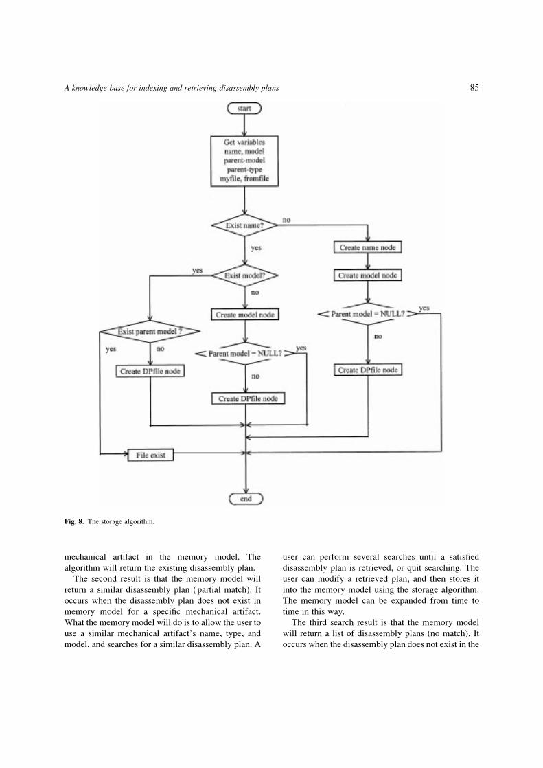
mechanical artifact in the memory model. The
algorithm will return the existing disassembly plan.
The second result is that the memory model will
return a similar disassembly plan ( partial match). It
occurs when the disassembly plan does not exist in
memory model for a speci®c mechanical artifact.
What the memory model will do is to allow the user to
use a similar mechanical artifact's name, type, and
model, and searches for a similar disassembly plan. A
user can perform several searches until a satis®ed
disassembly plan is retrieved, or quit searching. The
user can modify a retrieved plan, and then stores it
into the memory model using the storage algorithm.
The memory model can be expanded from time to
time in this way.
The third search result is that the memory model
will return a list of disassembly plans (no match). It
occurs when the disassembly plan does not exist in the
Fig. 8. The storage algorithm.
A knowledge base for indexing and retrieving disassembly plans 85
memory model, and the user knows the structure of
the mechanical artifact roughly. The ®nal disassembly
plan (or plans) will be the intersection of the lists.
Based on the retrieved disassembly plan (or plans),
the user can choose one, modi®es it, and then stores it
back into the memory model. If no disassembly plan is
retrieved from the memory model, the user has to
create a new disassembly plan, then adds it into the
memory model. This algorithm requires the user to
have more knowledge about the mechanical artifact
structure. The searching ¯ow chart is shown in Fig. 9.
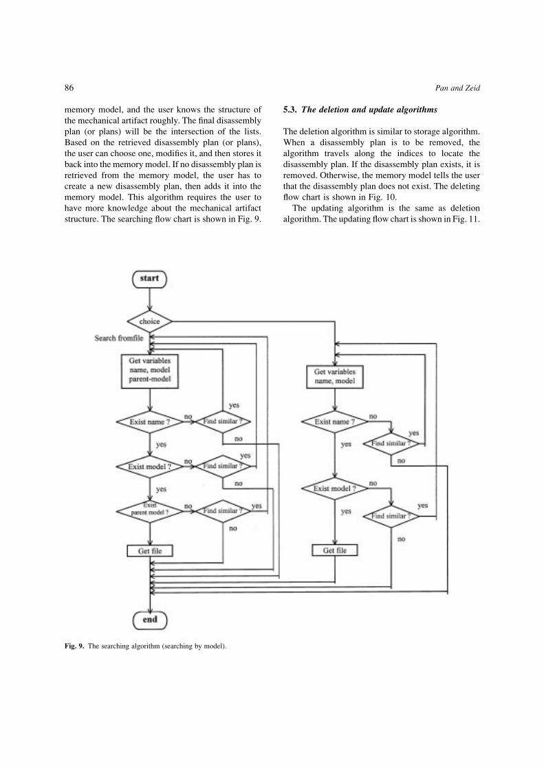
5.3. The deletion and update algorithms
The deletion algorithm is similar to storage algorithm.
When a disassembly plan is to be removed, the
algorithm travels along the indices to locate the
disassembly plan. If the disassembly plan exists, it is
removed. Otherwise, the memory model tells the user
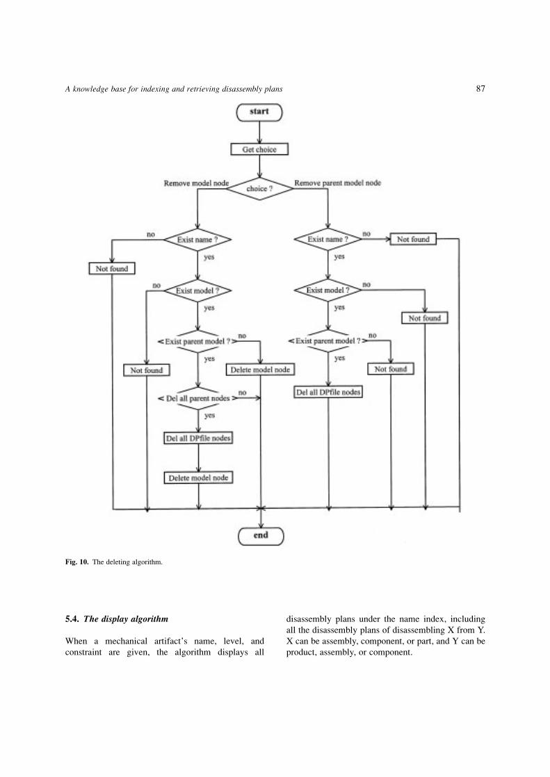
that the disassembly plan does not exist. The deleting
¯ow chart is shown in Fig. 10.
The updating algorithm is the same as deletion
algorithm. The updating ¯ow chart is shown in Fig. 11.
Fig. 9. The searching algorithm (searching by model).
86 Pan and Zeid
5.4. The display algorithm
When a mechanical artifact's name, level, and
constraint are given, the algorithm displays all
disassembly plans under the name index, including
all the disassembly plans of disassembling X from Y.
X can be assembly, component, or part, and Y can be
product, assembly, or component.
Fig. 10. The deleting algorithm.
A knowledge base for indexing and retrieving disassembly plans 87

6. Implementation
The memory model described above is implemented
in C� � . The proposed memory model is imple-
mented using a hash table with a linked
representation. There are several ways for data
representations. An array is a kind of sequential list
representation, which is static storage. The advantage
of an array is space ef®ciency. The drawback is bad
time ef®ciency with inconvenient inserting and
deleting (which means orderly sequential representa-
tion). When the data size increases from time to time,
the array representation increases the running time
greatly. The size of an array is also dif®cult to
predetermine when the data size is uncertain at the
programming stage in languages such as C or C� � .
Fig. 11. The update algorithm.
88 Pan and Zeid

If the array size is too big, the advantage of space
ef®ciency is lost. If the array size is too small, an
over¯ow will occur during the run time of a program.
Using the linked representation can overcome the
disadvantages of a sequential list representation.
However, these linked representations have disadvan-
tages of their own, such as inef®cient access of the ithlist item, and storage penalties for the space needed to
store the links (Standish, 1994). The linked repre-
sentation of data can allocate memory space
dynamically. The advantage of linked representation
is the ef®ciency of operations, i.e., time ef®ciency.
The tradeoff is the memory space cost. Single/double
linked list, AVL tree are all kinds of a linked
representation. Hash tables have combined the
advantages of both sequential and linked representa-
tion. The operations which are used in the memory
model have O(1) running time. From Table 2, the
advantage of hashtable is obvious.
The memory model is implemented using eight
hash tables corresponding to the eight categories
mentioned in previous section. For each hash table, a
link list is formed. The entire program consists of ®ve
classes. They include:
* Class of hashtable: A class de®ning the
common characteristics of all hash tables. The
hash table contains an array of hashbuckets, into
which entries are stored. Each hash table is an
EMOP that is an organizer. Each hash table
organizes one of the eight categories. New
disassembly plan can be added according to
the combination of a mechanical artifact's level
and disassembling operation constraints.
Existing disassembly plan can be deleted by
indices of a mechanical artifact's level and
constraint. Search can be performed using the
same indices as adding and deleting.* Class of hashbucket: A class de®ning the
bucket. Each bucket contains a linked list of
hashentry pointers. A hashbucket is a
SUBEMOP, which organizes a series of disas-
sembly plans. Every mechanical artifact's name
is hashed by the hash function. According to the
hashing result, mechanical artifacts are distrib-
uted evenly into hashbuckets. In each
hashbucket, the mechanical artifacts are
arranged in alphabetical order. New disassembly
plans can be added by mechanical artifacts'
name. Existing disassembly plans can be deleted
by the index of name, and search can be
performed for an index of a given name.* Class of hashentry (Name-Node): A class
de®ning the features of entries in a bucket's
linked list. Each entry (node) contains a
mechanical artifact's name, which distinguishes
it from others. Every hashentry (node) contains a
few model indices.* Class of my®le (Model-Node): A class de®ning
the features of Model-Node. Each node contains
a mechanical artifact model, which can be used
to identify this mechanical artifact from other
similar ones. It also contains the disassembly
plan of this model. Under each model node, a
few of model indices are contained.* Class of from®le (DP®le-Node): A class
de®ning the features of DP®le-Node. Each
node contains a parent model, which can be
distinguished from other siblings. Each node
contains a disassembly plan of disassembling a
mechanical artifact from its parent mechanical
artifact. The parent type of a mechanical artifact
is stored. The feature of parent type can be used
to help the search algorithm to retrieve a better
similar disassembly plan whenever a product
structure is given.
7. Examples
To illustrate the use and versatility of the proposed
memory model, disassembly plans of some mechan-
Table 2. Comparative performance of data
Operationsrepresentations Initialize Determine if full Search Retrieve Update Insert Delete Enumerate
Sorted array O(n) O(1) O(log n) O(n) O(n) O(n)
Sorted link list (single) O(n) O(1) O(n) O(n) O(n) O(n)
AVL tree O(1) O(1) O(log n) O(log n) O(log n) O(n)
Hash table O(n) O(1) O(1) O(1) O(1) O(n log n)
A knowledge base for indexing and retrieving disassembly plans 89
ical artifacts are introduced to the memory model.
These artifacts are two-stroke engines, air ®lter, and
carburetor. The following sections show the memory
model after each mechanical artifact is added to the
system. A series of retrieval requests is discussed after
the disassembly plans being stored.
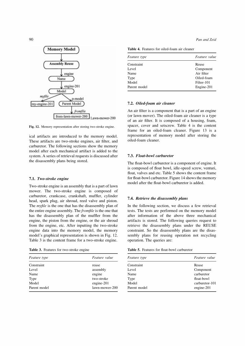
7.1. Two-stroke engine
Two-stroke engine is an assembly that is a part of lawn
mower. The two-stroke engine is composed of
carburetor, crankcase, crankshaft, muf¯er, cylinder
head, spark plug, air shroud, reed valve and piston.
The my®le is the one that has the disassembly plan of
the entire engine assembly. The from®le is the one that
has the disassembly plan of the muf¯er from the
engine, the piston from the engine, or the air shroud
from the engine, etc. After inputting the two-stroke
engine data into the memory model, the memory
model's graphical representation is shown in Fig. 12.
Table 3 is the content frame for a two-stroke engine.
7.2. Oiled-foam air cleaner
An air ®lter is a component that is a part of an engine
(or lawn mover). The oiled-foam air cleaner is a type
of an air ®lter. It is composed of a housing, foam,
spacer, cover and setscrew. Table 4 is the content
frame for an oiled-foam cleaner. Figure 13 is a
representation of memory model after storing the
oiled-foam cleaner.
7.3. Float-bowl carburetor
The ¯oat-bowl carburetor is a component of engine. It
is composed of ¯oat bowl, idle-speed screw, venturi,
¯oat, valves and etc. Table 5 shows the content frame
for ¯oat-bowl carburetor. Figure 14 shows the memory
model after the ¯oat-bowl carburetor is added.
7.4. Retrieve the disassembly plans
In the following section, we discuss a few retrieval
tests. The tests are performed on the memory model
after information of the above three mechanical
artifacts is stored. The following queries request to
retrieve the disassembly plans under the REUSE
constraint. So the disassembly plans are the disas-
sembly plans for reusing operation not recycling
operation. The queries are:
Fig. 12. Memory representation after storing two-stroke engine.
Table 3. Features for two-stroke engine
Feature type Feature value
Constraint reuse
Level assembly
Name engine
Type two-stroke
Model engine-201
Parent model lawn-mower-200
Table 4. Features for oiled-foam air cleaner
Feature type Feature value
Constraint Reuse
Level Component
Name Air ®lter
Type Oiled-foam
Model Filter-101
Parent model Engine-201
Table 5. Features for ¯oat-bowl carburetor
Feature type Feature value
Constraint Reuse
Level Component
Name carburetor
Type ¯oat-bowl
Model carburetor-101
Parent model engine-201
90 Pan and Zeid

* Retrieve the disassembly plan of a four-stroke
engine.
A four-stroke engine differs from a two-stroke engine.
The major distinction is the position of the carburetor
and air ®lter. In the two-stroke engine, the air±fuel
mixture enters the engine through the crankcase, the
intake port (and thus the carburetor and air ®lter) is at
the base of the cylinder and crankcase. For the four-
stroke engine, the intake port is at the cylinder head.
Otherwise, the parts are identical. A ¯exible fuel line
connects the fuel tank to the carburetor; a ¯ywheel,
covered by a metal shroud, is attached to one end of
the crankshaft; a muf¯er covers the exhaust port; and
a spark plug is screwed into the cylinder head (Time
Life Books, 1982). The features of four-stroke engine
are in Table 6.
The model will search all the disassembly plans
under name ENGINE. Since there is no disassembly
plan for four-stroke engine which has MODEL
engine-401, the memory model will tell the user that
the disassembly plan for four-stroke engine is not
available. The user has three choices. First, the user
can choose a similar engine model if he/she knows
how to choose one. The memory model will search
again, and return a result of either found or not found.
Second, the user can select to display all the
disassembly plans under name ENGINE if the user
does not know which one should be chosen. Finally,
the user can input the structure of the four-stroke
engine. The memory model will search and retune a
result. If the user chooses to retrieve a disassembly
plan of two-stroke engine instead, the model will
return My-engine-201. After the ®le returned, the
model will ask if the user wants to modify the
retrieved disassembly plan. If the user changes the
disassembly plan, the new disassembly plan is stored
into the memory model. In this example, the same
disassembly plan is used since the two engines'
structures are similar, which means the disassembly
sequences will be the same. Hence the same
disassembly plan will be referenced. Figure 15
shows the memory model after storing the disas-
sembly plan of four-stroke engine.
* Retrieve the disassembly plan for disassembling
the four-stroke engine from garden tiller.
The features are the same as in Table 6. The retrieval
procedure is the same as the previous query. The
memory model representation is illustrated in Fig. 16.
* Retrieve the disassembly plan for oiled-foam air
cleaner FILTER-101.
Fig. 13. Memory model after storing oiled-foam air cleaner and two-stroke engine.
Table 6. Features for four-stroke engine
Feature type Feature value
Constraint Reuse
Level Assembly
Name Engine
Type Four-stroke
Model Engine-401
Parent model Garden-tiller-400
A knowledge base for indexing and retrieving disassembly plans 91

The features are the same as in Table 4.
The model will return the disassembly plan stored
in the ®le My-®lter-101.
* Retrieve the disassembly plan for disassembling
the oiled-foam air cleaner FILTER-101 from
ENGINE-201.
Fig. 14. Memory model representation after storing two-stroke engine, oiled-foam air cleaner, and ¯oat-bowl carburetor.
Fig. 15. Memory model representation after storing the four-stroke engine.
Table 7. Features for oil-bath air cleaner
Feature type Feature value
Constraint Reuse
Level Component
Name Air ®lter
Type Oil-bath
Model Filter-201
Parent model Engine-100*
Table 8. Features for dry-®lter cleaner
Feature type Feature value
Constraint Reuse
Level Component
Name Air ®lter
Type Dry-®lter
Model Filter-301
Parent model Engine-200*
92 Pan and Zeid

The features are the same as in Table 4.
The model will return the disassembly plan stored
in the ®le From-engine-201.
* Retrieve the disassembly plan for oil-bath
cleaner FILTER-201.
The features are in Table 7.
The model will return ``not found'', and prompt the
user for continuing or not. In this example, suppose
the user wants to add the disassembly plan into the
memory model. The user can quit the search
Fig. 16. Memory model representation after storing the four-stroke engine disassembly plan.
Fig. 17. Memory model representation after storing all the mechanical artifacts and implementing all the search queries.
A knowledge base for indexing and retrieving disassembly plans 93

procedure and introduce the oil-bath cleaner FILTER-
201 into the memory model.
* Retrieve the disassembly plan for dry-®lter air
cleaner FILTER-301
The features are in Table 8.
The model returns ``no ®le''. Hence, the user may
want to see what disassembly plan the memory model
has. The user can quit the search and tell the system to
show all disassembly plans under the Name AIR
FILTER. After reading all the information on
screen, the user can decide which similar model to
be chosen.
After implementing all above queries, the memory
model representation is shown in Fig. 17. The more
the user uses the memory model, the larger the
memory model becomes. All the experiences are
stored into the memory model. People can refer the
experiences when they need them.
8. Conclusion
A memory model has been designed and implemented
for ef®cient saving and retrieval of disassembly plans
with the function to add/remove new/old disassembly
plans. In designing the memory model, information of
the products, such as name, type, model, parent model
and level, are used as features to index the product
memory model. This alleviates users from having to
know the detail of mechanical artifacts' structure. By
using hash tables, the memory model offers the
advantages of using minimal computer memory, fast
retrieving speed and easy adding/removing indices
and events ability. The model has been implemented
in C� � . Through case studies, the developed
memory model has shown to be valid and ef®cient
in supporting people to build a knowledge-based
disassembly plan database, and retrieve a disassembly
plan in the process of PFD.
References
Arai, E. and Iwata, K. (1993) CAD system with product
assembly/disassembly planning function, Robotics &Computer-Integrated Manufacturing 10(1/2), 41±48.
Arai, E., Uchiyama, N. and Igoshi, M. (1995) Disassembly
path generation to verify the assemblability of
mechanical products. JSME International Journal,Series C, 38(4), 805±810.
Bardasz, T. and Zeid, I. (1992) DEJAVU: A case-based
reasoning designers assistant shell. Arti®cialIntelligence, 477±496.
Beasley, D. and Martin, R. R. (1993) Disassembly
sequences for objects built from unit cubes.
Computer-Aided Design, 25(12), 751±761.
Boothroyd, G. and Alting, L. (1992) Design for assembly
and disassembly. Annals of CIRP, 41(2).
Brennan, L., Gupta, S. M. and Taleb, K. N. (1994)
Operations planning issues in an assembly/disassembly
environment. International Journal of Operations andProduction Management, 14(9), 57±67.
Corcoran, E. (January 1992) Green Machine, Volkswagen
gears up to recycle autos. Scienti®c American, 266,
140±141.
Grogan, P., (January 1994) Auto Wreckers. Biocycle, 35,
86.
Gupta, S. M. and Taleb, K. N. (1994) Scheduling
disassembly. International Journal of ProductionResearch, 32(8), 1857±1866.
Johnson, M. R. and Wang, M. H. (1995) Planning product
disassembly for material recovery opportunities.
International Journal of Production Research,
33(11), 3119±3141.
Kolodner, J. (ed.) (1984) Proceedings Retrieval andOrganizational Strategies in Conceptual Memory: AComputer Model, Lawrence Erlbaum, USA.
Penev, K. and DeRon, Ad J. (1996) Determination of a
disassembly strategy. Int. J. Prod. Res., 34(2) 495±506.
Penev, K. and DeRon, Ad J. (1994) Development of
disassembly line for refrigerators. IndustrialEngineering, 00, 50±53.
Schank, R. C. (1982) Dynamic Memory, Cambridge
University Press, Cambridge.
Schank, R. C. and Adelson, R. P. (1977) Scripts, Plans,Goals and Understanding. Lawrence Erlbaum,
Hillsdale, NJ.
Standish, T. A. (1994) Data Structures, Algorithms andSoftware Principles in C, Addison Wesley.
Time Life Books (eds.) (1982) Small engines. Home Repairand Journal of Production Research, 32(8), 1857±
1866.
Woo, T. C. (1991) Automatic disassembly and total ordering
in three dimensions. Journal of Engineering forIndustry, 113, 207±213.
Yokota, K. and Brough, D. R. (1992) Assembly/disas-
sembly sequence planning. Assembly Automation,
12(3), 31±38.
Zeid, I., Cupta S. and Bardasz, T. (1997) An analogical
problem solving approach to planning for disassembly,
TBD.
94 Pan and Zeid