A Hydro D ŒJ D Québec Hydro-Québec underground MV system 7 5.4 Point of distributed-generation...
40
ntations Denis Syste English editor Engineer's seal Verified by Concerned units Ali units of the Distribution System branch Prepared by Charles-Étienne Côté, Jr., Eng. Technical Orientations S stem Orientations A Hydro D Directive ŒJ Standard D Method Québec Number Distribution E.12-01 D Corporate ŒJ Sector-based Page 1 of 40 Tille Revision of version dated 2004/11 Requirements for the Interconnection of Distributed Generation Effective date to the Hydro-Québec Medium-Voltage Distribution System 1 PURPOSE AND APPLICATION 3 2 SCOPE 3 3 RELA TED GVIOLINES 3 4 DEFINITIONS ..... •...... •...••..•••.•..•.••.•••.•••••••.••••••.••••...•..... •...... •................ •.............. •.••.................... •................. •.. 4 5 CONFIGURATION OF THE HYDRO-QUÉBEC DISTRlBUTION SySTEM....... • .... • ................. • ............................ 6 5.1 General information 6 5.2 Hydra-Québec overhead MV system 7 5.3 Hydro-Québec underground MV system 7 5.4 Point of distributed-generation connection 7 6 CONNECTION TO THE HYDRO-QUÉBEC DISTRIBUTION SYSTEM 7 6.1 General requirements for the design, construction and operation of power producer facilities 7 6.2 Information to be transmitted to Hydro-Québec 8 6.3 Maximum power on a distribution line 8 6.4 Typical connection diagrams 9 7 VOLTAGE-RELATED REQUIREMENTS 9 7. J Voltage fluctuations 9 7.2 Harmonic distortion 9 7.3 Injection of direct current 90 7.4 Voltage regulation and power factor 10 8 REQlJlREMENTS REGARDrNG GENERATING STATION EQUIPMENT 11 8.1 Neutral-point connection Il 8.2 Disconnect point J J 8.3 Electrical characteristics of medium-voltage equipment 12 8.4 Type of generating equipment 12 2009/02 v. Date Recommende· Éric Le Courtois, Eng. Bruno Houle, Manager, LTE, Groupe Technologie TechnicalOrientations Date ir,U ACCEDWEB 210207-01 © Hydro-Québec
Transcript of A Hydro D ŒJ D Québec Hydro-Québec underground MV system 7 5.4 Point of distributed-generation...

ntations Denis Syste
English editor
Engineer's seal
Verified by
Concerned units
Ali units of the Distribution System branch
Prepared by />~ ~
\LJ.A{7{j't.tY.l,,~{ftY';s. Charles-Étienne Côté, Jr., Eng. Technical Orientations S stem Orientations
A Hydro D Directive ŒJ Standard D Method~ Québec NumberDistribution
E.12-01 D Corporate ŒJ Sector-based
Page 1 of 40
Tille Revision of version dated
2004/11Requirements for the Interconnection of Distributed Generation
Effective date to the Hydro-Québec Medium-Voltage Distribution System
1 PURPOSE AND APPLICATION 3
2 SCOPE 3
3 RELATED G VIOLINES 3
4 DEFINITIONS.....•......•...••..•••.•..•.••.•••.•••••••.••••••.••••...•.....•......•................•..............•.••....................•.................•.. 4
5 CONFIGURATION OF THE HYDRO-QUÉBEC DISTRlBUTION SySTEM.......•....•.................•............................ 6 5.1 General information 6 5.2 Hydra-Québec overhead MV system 7 5.3 Hydro-Québec underground MV system 7 5.4 Point of distributed-generation connection 7
6 CONNECTION TO THE HYDRO-QUÉBEC DISTRIBUTION SYSTEM 7 6.1 General requirements for the design, construction and operation of power producer facilities 7 6.2 Information to be transmitted to Hydro-Québec 8 6.3 Maximum power on a distribution line 8 6.4 Typical connection diagrams 9
7 VOLTAGE-RELATED REQUIREMENTS 9 7. J Voltage fluctuations 9 7.2 Harmonic distortion 9 7.3 Injection of direct current 90 7.4 Voltage regulation and power factor 10
8 REQlJlREMENTS REGARDrNG GENERATING STATION EQUIPMENT 11 8.1 Neutral-point connection Il 8.2 Disconnect point J J 8.3 Electrical characteristics of medium-voltage equipment 12 8.4 Type of generating equipment 12
2009/02
v . tob~~ Date Recommende·
'~'()~'a3~ Éric Le Courtois, Eng. Bruno Houle, Manager, LTE, Groupe Technologie TechnicalOrientations
Date
an~,ii.~ir,U
ACCEDWEB 210207-01 © Hydro-Québec

Directive ⌧ Standard Method Number
E.12-01 Corporate ⌧ Sector-based
Page 2 of 40
ACCEDWEB 210207-02 © Hydro-Québec
A
8.5 Surge arresters ...............................................................................................................................................13 8.6 Distribution and power transformers .............................................................................................................13 8.7 Main circuit breaker.......................................................................................................................................14 8.8 Reactor or resistor in the neutral....................................................................................................................15 8.9 Capacitors ......................................................................................................................................................15 8.10 Station services ..............................................................................................................................................15 9 REQUIREMENTS FOR THE PROTECTION OF GENERATING STATION EQUIPMENT .....................................16
10 REQUIREMENTS FOR THE PROTECTION OF THE HYDRO-QUÉBEC SYSTEM .............................................16 10.1 Types of protection ........................................................................................................................................16 10.2 Relay models .................................................................................................................................................18 10.3 Relay power supply .......................................................................................................................................18 10.4 Conditioning of main circuit breaker closing ................................................................................................19 10.5 Instrument transformers for protection ..........................................................................................................19 10.6 Protection coordination and settings..............................................................................................................19 10.7 Locking of protections...................................................................................................................................24 10.8 Protection study .............................................................................................................................................24 11 CONTROLGEAR........................................................................................................................................24 11.1 Voltage regulators..........................................................................................................................................24 11.2 Speed governors (synchronous generators) ...................................................................................................24 11.3 Generating station synchronization with the Hydro-Québec system.............................................................25 12 SPECIFIC REQUIREMENTS FOR WIND GENERATION ...................................................................................25 12.1 Requirements during undervoltage conditions and low-voltage ride-through (LVRT) ................................26 12.2 Voltage regulation .........................................................................................................................................26 12.3 Frequency control (inertial response) ............................................................................................................27 12.4 Requirement during frequency variations......................................................................................................27 12.5 Maximum up- and down-ramp rates..............................................................................................................27 12.6 Requirements regarding wind generator shutdown under forecast frigid or high-wind conditions ..............28 13 ISLANDED GENERATION ...............................................................................................................................28
14 OFF-GRID GENERATION (BACKUP) ..............................................................................................................28
15 RESPONSIBILITY FOR IMPLEMENTATION ...................................................................................................28
16 RESPONSIBILITY FOR APPLICATION............................................................................................................28
APPENDICES
A – Technical Information to be Transmitted to Hydro-Québec for the Distributed-Generation Plant Integration Study................................................................................................................... 30
B – Typical Connection and Protection Diagrams for Facilities .......................................................... 34
C – Content of Power Producer Protection Study ................................................................................ 39

Directive ⌧ Standard Method Number
E.12-01 Corporate ⌧ Sector-based
Page 3 of 40
ACCEDWEB 210207-02 © Hydro-Québec
A
1 PURPOSE AND APPLICATION
This standard defines the minimum requirements and technical specifications for the interconnection of distributed generation to the Hydro-Québec medium-voltage (MV) distribution system. The standard is also applicable when an existing generating station must be modified or upgraded.
Given the various means of generation, modes of interconnection and potential system constraints, Hydro-Québec may define certain specific requirements at the time each case is reviewed.
Wind generation is a rapidly evolving option that has a number of specific technical features. Section 12 herein sets out supplementary requirements specific to such technology.
2 SCOPE
This standard is intended for distributor personnel in charge of integrating distributed generation into the distribution system.
It is also intended for power producers with generating stations connected to the Hydro-Québec MV distribution system. They are required to comply with this standard.
3 RELATED GUIDLINES
This standard is part a series of guidelines governing technical requirements regarding the connection of power producing facilities to Hydro-Quebec's distribution network:
• E.12-03, Maintenance des équipements de protection des installations de production décentralisée se raccordant au réseau moyenne tension d’Hydro-Québec ;
• E.12-05, Exigences relatives au raccordement de la production décentralisée de 600 kVA et moins
au réseau basse tension d'Hydro-Québec;
• E.12-06, Exigences relatives au raccordement de la production décentralisée sans injection de puissance au réseau de distribution d'Hydro-Québec;
• E.12-07, Exigences relatives au raccordement de la production décentralisée utilisant des
onduleurs de faible puissance au réseau de distribution basse tension d'Hydro-Québec;
• E.12-08, Exigences relatives à la mise en parallèle momentanée d'équipements de production d'urgence avec le réseau de distribution d'Hydro-Québec;
• E.12-09, Exigences relatives à la qualification des équipements de protection utilisés pour le
raccordement de la production décentralisée sur le réseau de distribution d’Hydro-Québec;
• E.21-10, Service d'électricité en basse tension;

Directive ⌧ Standard Method Number
E.12-01 Corporate ⌧ Sector-based
Page 4 of 40
ACCEDWEB 210207-02 © Hydro-Québec
A
• E.21-11, Service d'électricité en basse tension à partir des postes hors réseau;
• E.21-12, Fourniture de l'électricité en moyenne tension;
• E.21-13, Exigences techniques relatives à la protection et à l'émission de perturbations des
installations de clients raccordées au réseau de distribution d'Hydro-Québec. Quebec regulations take precedence over this Standard in case of conflicting interpretations, and the French version of this Standard takes precedence over the English version in the event of discrepancies.
4 DEFINITIONS
Blocking: An operation designed to prevent continued conversion by a converter by preventing grid or gate pulses from impinging on the appropriate valve. This operation may also include turning on one or more selected valves to form a shunt path. Blocking thus enables a facility to remain in service without producing electrical power. Disconnecting switch: Equipment that connects or separates conductors. Distributor: Hydro-Québec Distribution. Fault: An unexpected change in mechanical or electrical characteristics that causes a short circuit. Generating set: A set of equipment used for the generation or conversion of electrical power. Generating station: A facility used to generate electrical power. It includes the electrical generating units, terminal station, instrumentation and protection equipment. Hydro-Québec service connection: A line that extends from a Hydro-Québec system line to the connection point. Islanding: The separation of a power system into subsystems, including load and generation, that occurs following a disturbance or switching operation. Low voltage (LV): Nominal voltage between phases that does not exceed 750 volts. Medium voltage (MV): Nominal phase-to-phase voltage of more than 750 volts up to and including 44,000 volts. Phase fault: A short circuit where one or more phases come into contact.

Directive ⌧ Standard Method Number
E.12-01 Corporate ⌧ Sector-based
Page 5 of 40
ACCEDWEB 210207-02 © Hydro-Québec
A
Phase-to-ground fault: A short circuit where a phase is in contact with the neutral conductor or ground. Point of common coupling (PCC): A point on the distribution system that is electrically nearest to the power producer, to which the facilities of other customers or power producers are or can be interconnected. Point of distributed-generation connection: A point where a power producer electrical facility is connected to the Hydro-Québec system. Power producer: A person, company, corporation or organization, including Hydro-Québec, that owns or leases an electrical generating station. A neighboring system to Hydro-Québec is not considered to be a power producer. Power producer connection: Any portion of the power producer electrical facility, from its terminal station to the connection point, inclusively. Power system with effectively grounded neutral-point connection: A power system where the neutral-point connection is effectively grounded and that meets the following two conditions:
X0/X1 ≤ 3 and R0/X1< 1
Where
X0 : Zero-phase sequence reactance X1 : Positive-sequence reactance R0 : Zero-phase sequence resistance
Primary winding of power producer transformers: The transformer winding on the Hydro-Québec system side. Reserved line: A Hydro-Québec medium-voltage distribution line (including the feeder at the distribution substation) intended for the exclusive use of a power producer. Resistive phase-to-ground fault: A short circuit where a phase is in contact with the neutral conductor or ground through a resistor. Secondary winding of power producer transformers: The transformer winding on the generating equipment side. Terminal station: A station which connects power producer facilities to the distribution system. The terminal station is made up of the medium-voltage part and includes step-up transformers starting at the low-voltage terminal. When more than one level of transformation is required at the terminal station, the transformers associated with these levels are also included.

Directive ⌧ Standard Method Number
E.12-01 Corporate ⌧ Sector-based
Page 6 of 40
ACCEDWEB 210207-02 © Hydro-Québec
A
Three-phase fault: A short circuit where all three phases are in contact.
5 CONFIGURATION OF THE HYDRO-QUÉBEC DISTRIBUTION SYSTEM
5.1 General information
The Hydro-Québec medium-voltage system operates with a neutral regime which is effectively grounded and is made up of single- and three-phase distribution lines.
A three-phase connection is used to connect a medium-voltage generating station. It is usually made at a nominal voltage of 25 kV (14.4/24.94 kV). When the connection is made at a voltage level of less than 25 kV, the facilities must be designed so as to be connected at the voltage level existing at the time of the connection and at 25 kV, unless Hydro-Québec has sent a written exemption to the power producer.
When the distribution system voltage is greater than 25 kV, Hydro-Québec shall inform the power producer of the system’s specific requirements.
Voltage is supplied under the provisions of the Conditions for Electrical Service and under CAN3-C235-83, which was prepared by the Canadian Electricity Association and approved by the Canadian Standards Council. Table I presents the nominal voltage levels taken from the Conditions for Electrical Service.
Table I Nominal voltage levels for the MV distribution system
Nominal line-to-neutral voltage (kV) Nominal line-to-line voltage (kV) 2.4 4.16 7.2 12.47 7.6 13.2 8.0 13.8
14.4 24.94 20.0 34.5
44.0
Under normal operating conditions, the planned voltage level for the Hydro-Québec distribution system is maintained within the range of 115 to 125 V on a 120-V basis.
For medium-voltage systems, the typical negative-sequence voltage unbalance ratio (V2/V1) under normal operating conditions is less than 2%. It may exceed 2% at some locations.

Directive ⌧ Standard Method Number
E.12-01 Corporate ⌧ Sector-based
Page 7 of 40
ACCEDWEB 210207-02 © Hydro-Québec
A
5.2 Hydro-Québec overhead MV system
The Hydro-Québec medium-voltage distribution system consists primarily of overhead lines. The three-phase portion of these lines generally consists of three phase conductors and one neutral conductor.
5.3 Hydro-Québec underground MV system
The Hydro-Québec medium-voltage system consists partially of underground lines. The three-phase portion of these lines generally consists of three single-phase stranded cables with a concentric neutral.
If the Hydro-Québec medium-voltage distribution system is underground, the power producer connection must also comprise an underground line. It is recommended that power producers install a backup line or cable.
5.4 Point of distributed-generation connection
The connection point serves as a dividing line between the Hydro-Québec system and that of the power producer. To ensure safety when servicing or isolating the system, a lockable disconnecting device is installed, making it possible to visually or positively verify the separation of the electrical isolation point (Hydro-Québec, Method D.24-20). This device can only be operated by Hydro-Québec personnel. The location of the connection point varies from one system configuration to the next, but the connection point must be in a location that can be accessed at all times by Hydro-Québec employees without requiring a third party. The switch belongs to Hydro-Québec, which is responsible for its maintenance and operation.
5.4.1 Connection point to the Hydro-Québec overhead MV system
The connection point is located where power producer connection conductors are connected to the end-of-line insulators of the support structure on which Hydro-Québec has installed the switch.
5.4.2 Connection point to the Hydro-Québec underground MV system
The connection point is located at the power producer cable potheads in the civil structure housing the switch installed by Hydro-Québec.
6 CONNECTION TO THE HYDRO-QUÉBEC DISTRIBUTION SYSTEM
6.1 General requirements for the design, construction and operation of power producer facilities
Power producer equipment and facilities must comply with the codes, standards and rules applicable in Québec as well as with standard public utility practices.

Directive ⌧ Standard Method Number
E.12-01 Corporate ⌧ Sector-based
Page 8 of 40
ACCEDWEB 210207-02 © Hydro-Québec
A
Power producer facilities must be designed, constructed and operated so as to not cause generating station tripping within the must-not-trip zone, and to cause tripping within the must-trip zones defined in Section 10.6.
Supplementary requirements specific to wind generators and wind power plants are given in Section 12.1.
6.2 Information to be transmitted to Hydro-Québec
Integrating a generating station into the distribution system may require modifications to existing Hydro-Québec facilities. The power producer must provide Hydro-Québec with the information specified in Appendix A of this standard so that Hydro-Québec can conduct a preliminary study that will allow it to determine the modifications that must be made and establish the conditions under which the generating station is to be connected to the distribution system. This information will allow Hydro-Québec to monitor the generating facilities connected to its system.
6.3 Maximum power on a distribution line
The maximum power from a generating station that can be carried by a distribution line is limited by the following factors:
• Line voltage, following generation interconnection • Capacity of Hydro-Québec system components • Stability of power producer generating facilities during disturbances or load variations on
the Hydro-Québec system • Voltage fluctuations during generating station startup or shutdown • Protection coordination and service quality
During the preliminary study, the Hydro-Québec distribution system planning representative assesses the power producer’s integration request and determines whether the generating station exceeds the maximum power that can be connected to the distribution system involved.1
6.4 Typical connection diagrams
For information purposes, standard single-line diagrams of connections that comply with the requirements of this standard are provided in Appendix B. Other connection configurations may be acceptable, provided they comply with this document.
1. Standard E.12-02 provides details on this point.

Directive ⌧ Standard Method Number
E.12-01 Corporate ⌧ Sector-based
Page 9 of 40
ACCEDWEB 210207-02 © Hydro-Québec
A
7 VOLTAGE-RELATED REQUIREMENTS
7.1 Voltage fluctuations
Flicker level at the connection point caused by power producer facilities must be within the limits specified in Standard C.22-03, Exigences techniques relatives au raccordement des charges fluctuantes au réseau de distribution d'Hydro-Québec [technical requirements for connecting fluctuating loads to the Hydro-Québec distribution system]. Voltage fluctuations to be considered when calculating flicker exclude transient phenomena lasting less than two 60-Hz periods. Such fluctuations may, for instance, be caused by capacitor bank switching, and by starting up or shutting down motors or generators.
The maximum allowable voltage flicker is specified as a function of the frequency of fluctuations. In the event that the power producer has more than one equipment which could cause voltage fluctuations, the cumulative effects must be evaluated in accordance with Standard C.22-03.
The power producer must calculate voltage fluctuations using data from the Hydro-Québec system at the point of common coupling when its facilities contain equipment likely to cause voltage fluctuations. To do so, Hydro-Québec will provide the power producer with the minimum short-circuit level as well as the location of the point of common coupling to be used for the calculations.
7.2 Harmonic distortion
Voltage and current distortion caused by harmonics must meet the requirements in force for industrial facilities.
The power producer must perform harmonic distortion calculations using data from the Hydro-Québec system at the point of common coupling if its facilities contain equipment likely to produce harmonics. Precise indications on the calculation method to be used can be found in Standard C.25-01, Exigences techniques relatives à l'émission d'harmoniques par les installations de clients raccordées au réseau de distribution d'Hydro-Québec [technical requirements for harmonic emissions by customer facilities connected to the Hydro-Québec distribution system].
When any of the harmonic disturbance limits is exceeded, the power producer facility must be modified or equipped with filters to limit the emission of harmonic currents onto the Hydro-Québec system. When such filters are required, the power producer must reevaluate the previous indicators to demonstrate that it has complied with the prescribed limits by adding filters. Hydro-Québec may require that other measures be implemented on the system to ensure that power producer facilities comply with prescribed limits.
7.3 Injection of direct current
No generating station should, under any circumstances, generate direct current with an amplitude exceeding 0.5% of its nominal current. Although this requirement is a general one, it applies more specifically to facilities equipped with inverters.

Directive ⌧ Standard Method Number
E.12-01 Corporate ⌧ Sector-based
Page 10 of 40
ACCEDWEB 210207-02 © Hydro-Québec
A
7.4 Voltage regulation and power factor
The generating station must be designed so that, under normal operating conditions, the voltage at the connection point is always maintained within the allowable limits, as presented in Section 5.1. The power producer must thus ensure that its generating station is able to generate full active power at all times without the voltage level at the connection point exceeding the limits allowed under normal operating conditions.
Section 12.2 presents requirements specific to wind power plants. In general, at the connection point, generating stations must maintain a power factor as close as possible to unity.
7.4.1 Equipment with voltage regulation capability
This category of equipment includes synchronous generators, inverters that can control power factor, and double-fed induction generators.
At the connection point, the power factor must be as close as possible to unity as long as the voltage level lies within the allowable range (see Section 5.1).
Under certain conditions, maintaining a unit power factor may temporarily lead to overvoltages on the distribution system. During such situations, voltage-regulating equipment must be capable of dynamically absorbing the reactive power required to maintain the voltage within the limits allowed under normal operating conditions.
Moreover, when maintaining a unity power factor could result in inadequate operation of voltage-regulating equipment on the system, Hydro-Québec may request that generating facilities generate or absorb enough reactive power to maintain a voltage level at the connection point which ensures proper operation of the Hydro-Québec system.
Power producer facilities must be designed to supply or absorb, at the generating station output (distribution system side), reactive power equivalent to an overexcited or underexcited nominal power factor less than or equal to 0.95. This reactive power must be available throughout the entire range of active power generation capacity.
High-capacity (more than 5 MW) power producer facilities may have to be designed to supply or absorb, at the generating station output (system side), reactive power equivalent to an overexcited or underexcited nominal power factor less than or equal to 0.9.

Directive ⌧ Standard Method Number
E.12-01 Corporate ⌧ Sector-based
Page 11 of 40
ACCEDWEB 210207-02 © Hydro-Québec
A
7.4.2 Equipment with no voltage regulation capability
This category of equipment includes inverters that cannot control the power factor and permanent-magnet synchronous generators.
When reactive power cannot be supplied or absorbed, the power factor at the generating station connection point must be such that the facility complies with the allowable voltage limits under normal operating conditions at the connection point, while being as close as possible to unity.
7.4.3 Facilities with induction generators
The reactive power required to operate induction generators comes from the power producer facilities and Hydro-Québec system (see sections 8.4 and 8.9).
8 REQUIREMENTS REGARDING GENERATING STATION EQUIPMENT
8.1 Neutral-ground regime
The type of connection preferred by Hydro-Québec is one where the characteristics of the generating station equipment are such that the neutral regime, at the connection point, is effectively grounded under both normal operating conditions and fault conditions.
8.2 Disconnect point
A lockable disconnecting device, belonging to the power producer, is required inside power producer facilities so that Hydro-Québec personnel can service the Hydro-Québec disconnecting device installed at the connection point. The power producer disconnecting device must make it possible to visually or positively verify the separation at the electrical isolation point (Hydro-Québec, Method D.24-20). A drawout circuit breaker may serve as a disconnect point, provided that Hydro-Québec personnel can lock out access to the cell enclosing the circuit breaker module.
In all cases, sufficient space must be provided for installing temporary grounds.

Directive ⌧ Standard Method Number
E.12-01 Corporate ⌧ Sector-based
Page 12 of 40
ACCEDWEB 210207-02 © Hydro-Québec
A
8.3 Electrical characteristics of medium-voltage equipment
Table II gives the electrical characteristics of medium-voltage equipment with which power producer equipment must comply.
Table II Electrical characteristics of medium-voltage equipment
ELECTRICAL CHARACTERISTIC NOMINAL SYSTEM VOLTAGE
12.47 kV 13.2 kV 13.8 kV 24.94 kV 34.5 kV
and 44 kV
Maximum RMS operating voltage 13.2 kV 13.97 kV 14.6 kV 26.4 kV (note 3)
Lightning impulse withstand voltage with respect to ground and between terminals (kV peak)
125 kV (note 1)
125 kV (note 1)
125 kV (note 1)
125 kV (note 2) (note 3)
Minimum symmetrical breaking capacity on a three-phase short circuit (for circuit breakers and fuses)
12 kA (note 1)
12 kA (note 1)
12 kA (note 1) 12 kA (note 3)
Minimum asymmetrical making current on a three-phase transient short circuit (kA peak) with a 2.7 asymmetry factor
32.4 kA (note 1)
32.4 kA (note 1)
32.4 kA (note 1) 32.4 kA (note 3)
20-cycle short-duration RMS current 12 kA (note 1)
12 kA (note 1)
12 kA (note 1) 12 kA (note 3)
Power-frequency withstand voltage (1 minute) (phase-to-ground and between terminals)
50 kV (note 1)
50 kV (note 1)
50 kV (note 1) 50 kV (note 3)
Rated voltage for surge arresters (phase-to-ground) 10 kV 10 kV 10 kV 21 kV (note 3)
Steady-state voltage for surge arresters (Uc or MCOV) 8.4 kV 8.4 kV 8.4 kV 17 kV (note 3)
Notes
1. All equipment used initially at a supply voltage below 24.94 kV must have the same characteristics as equipment used at 24.94 kV.
2. This value also applies to transformers with solid-core insulation and oil-insulated transformers. With respect to air-break disconnect switches, a lightning impulse withstand voltage of 136.5 kV (125 kV +10%) is required when the contacts are open.
3. Characteristics available upon request.
8.4 Type of generating equipment
The choice of generating equipment is left to the power producer’s discretion, except when generation could adversely affect voltage regulation on the Hydro-Québec system. In such a case, Hydro-Québec may require that power producer facilities be equipped with synchronous generators or inverters able to supply or absorb enough reactive power to ensure proper operation of the Hydro-Québec system (see Section 7.4).
Directive ⌧ Standard Method Number
E.12-01 Corporate ⌧ Sector-based
Page 13 of 40
ACCEDWEB 210207-02 © Hydro-Québec
A
8.5 Surge arresters
Heavy-duty, gapless, distribution-class surge arresters must be installed in power producer facilities upstream of all of its equipment. In addition, metal oxide varistors (MOVs) must be used. Surge arresters that are not explosion-proof must be installed at least 15 metres from any Hydro-Québec installation, unless they are equipped with mechanical protection (metal enclosure or other device).
8.6 Distribution and power transformers
8.6.1 Characteristics
Transformer characteristics must comply with the specifications of CAN/CSA-C2-M91, CAN/CSA-C88-M90 or CAN/CSA-C9-M1981, depending on the type of equipment.
Hydro-Québec recommends that each transformer be equipped with voltage taps so that it meets voltage-related requirements.
8.6.2 Connection types
The connection type of generating station transformers affects the neutral regime of the facility. For the generating station neutral regime to be effectively grounded, the transformer primary winding must be grounded either directly or through some impedance (see Section 8.8), as shown in Figure 1. In addition, the following criteria must be met:
X0/X1 ≤ 3 and R0/X1< 1
Where X0 – Zero-phase sequence reactance X1 – Positive-sequence reactance R0 – Zero-phase sequence resistance

Directive ⌧ Standard Method Number
E.12-01 Corporate ⌧ Sector-based
Page 14 of 40
ACCEDWEB 210207-02 © Hydro-Québec
A
Hydro-Québec MV system
Power producer system
Hydro-Québec MV system
Grounding impedance
Power producer system
Figure 1 – Transformer connection for an effectively grounded neutral-point connection
8.6.3 Connection without a transformer
The use of a transformer between the Hydro-Québec system and power producer generating equipment is optional if the nominal voltage of the generating equipment allows direct connection and the neutral regime, at the connection point, complies with conditions agreed upon with Hydro-Québec (see Section 8.6.2). However, the power producer must bear in mind that an installation with no coupling transformer may result in the following drawbacks:
• Generating equipment would not benefit from the protection provided by the transformer during voltage surges due to lightning.
• In the event of a fault, there may be overcurrent in the generator winding (welding of plates and destruction of the generator).
• There would be no third harmonic filter (assuming a delta connection on the secondary side).
• The installation would not benefit from the advantage of voltage taps to meet the voltage regulation requirements specified in Section 7.4.
8.7 Main circuit breaker2
Power producer facilities must be equipped with circuit breakers so that neither they nor Hydro-Québec facilities are damaged. The main circuit breaker serves to simultaneously isolate all power producer equipment from distribution system equipment and must be located upstream (i.e., on the distribution system side) of the power producer equipment. Tripping of the main circuit breaker will be triggered by the various relays or protection systems. The main circuit breaker should have sufficient breaking 2. For low-capacity generating stations, it may be possible to replace the main circuit breaker with a fuse set. In such a case, the main circuit breaker would have to be installed on the secondary side of the transformer with an added phase-balance current relay (function 46). Fuse protection must be coordinated with Hydro-Québec protection and approved by Hydro-Québec.

Directive ⌧ Standard Method Number
E.12-01 Corporate ⌧ Sector-based
Page 15 of 40
ACCEDWEB 210207-02 © Hydro-Québec
A
capacity to interrupt faults of all kinds that may occur in the power producer facilities or on the Hydro-Québec system.
When several generating units connected through independent transformers are used, Hydro-Québec may agree to the power producer facilities being equipped with more than one main circuit breaker. Table II shows the characteristics that must be met by circuit breakers connected to the Hydro-Québec medium-voltage system.
8.8 Reactor or resistor in the neutral
It may be necessary to use a reactor or resistor in the neutral of the main transformer or in each neutral of generating station generators to decrease the generating station’s contribution to phase-to-ground faults on the Hydro-Québec system and to comply with the protection rules listed in Section 10.6.1. The impedance value depends on the characteristics of the Hydro-Québec system and those of the power producer facility. It must be established by the power producer and approved by Hydro-Québec. It must be such that the neutral regime, at the connection point, remains effectively grounded.
8.9 Capacitors
In order to improve the low power factor of induction generators, capacitor banks must be installed in the power producer facility. However, Hydro-Québec may limit the amount of reactive compensation in order to prevent the following phenomena:
• Rapid rise in voltage (possibly 2 p.u. in 1 second) that may result in ferroresonance and self-excitation following islanding on part of the Hydro-Québec system
• Overvoltages on the Hydro-Québec system in steady state during low-load conditions
Hydro-Québec establishes the maximum amount of compensation based on the characteristics of both station generators and the distribution system. Any reactive power deficit with respect to a unit power factor must be offset by installing other reactive-compensation devices at more suitable locations on the Hydro-Québec system. The capacitor banks authorized for use at the generating station must be connected to each generating unit (on a proportional basis) so that a normal or forced shutdown of a generating unit will trip the associated capacitors in order to maintain an adequate compensation ratio.
8.10 Station auxiliary services
The station auxiliary services, required for generating station operation, must remain operational at all times and not directly or indirectly cause tripping during voltage and frequency variations within the must-not-trip zones as described in Section 10.6.

Directive ⌧ Standard Method Number
E.12-01 Corporate ⌧ Sector-based
Page 16 of 40
ACCEDWEB 210207-02 © Hydro-Québec
A
9 REQUIREMENTS FOR THE PROTECTION OF GENERATING STATION EQUIPMENT
The power producer is responsible for adequately protecting its equipment. The power producer must ensure that protection systems are sufficient in number and are able to perform the proper functions to protect its equipment against all faults and both normal and abnormal operating conditions on the Hydro-Québec system and in power producer facilities. As a matter of fact, certain operating conditions on the Hydro-Québec system and in power producer facilities may cause overvoltages or resonance phenomena (e.g., self-excitation of machines, ferroresonance and subsynchronous resonance when series compensation is used on the grid). In order to control the effects of such phenomena on its system, Hydro-Québec may impose additional requirements or restrictions applicable to some operating modes of the power producer facilities. In addition, the power producer must adequately protect its equipment against any potential voltage and current unbalances resulting from particular operating conditions and from normal load unbalances on the Hydro-Québec system. Such unbalances may cause the flow of zero-phase and negative-sequence current, thus causing generator overheating and potential damage.
Protection systems used to protect power producer facilities must be sufficiently selective to avoid undesirable tripping during major events causing transient disturbances affecting voltage, power or frequency on the Hydro-Québec transmission or distribution systems. Thus, no protection system may directly or indirectly cause tripping during voltage or frequency variations within the must-not-trip zones specified in Section 10.6.
10 REQUIREMENTS FOR THE PROTECTION OF THE HYDRO-QUÉBEC SYSTEM
This section covers Hydro-Québec requirements regarding protection systems installed at the generating station to ensure the protection of the Hydro-Québec system. Power producer facilities must comply with these requirements; hence, the power producer must supply and install the various required protection devices within its facilities. For reference purposes, Appendix B presents typical connection and protection diagrams for facilities.
10.1 Types of protection
The minimum protection functions required by Hydro-Québec to protect its system are listed below. They are designed to detect all types of faults and disturbances that may affect the Hydro-Québec system.

Directive ⌧ Standard Method Number
E.12-01 Corporate ⌧ Sector-based
Page 17 of 40
ACCEDWEB 210207-02 © Hydro-Québec
A
10.1.1 Primary or fault protection
Primary protection consists of line protection. It includes protection against phase and neutral overcurrents (functions 50/51 and 50/51N).
However, the following situations may make overcurrent protection inefficient and unacceptable:
• The generating station comprises several generating units, one or more of which may be out of service. (The generating station’s contribution to the fault may then be insufficient for meeting the rules specified in Section 10.6.1.)
• The characteristics of the generating equipment (generators) are unknown.
• The technology used does not allow sufficient overcurrent to be produced to meet the rules specified in Section 10.6.1.
• The generating station’s contribution to the fault is too great and is degrading fuse coordination on the Hydro-Québec system.
In such cases, distance relay protection with several phase and ground levels (function 21) could be used. At the power producer’s request and following Hydro-Québec’s approval, distance relay protection may be replaced with voltage-restrained time overcurrent protection (function 51V) and neutral overcurrent protection (functions 50/51N).
10.1.2 Backup or islanding protection
These protections mainly detect situations that may lead to generating station islanding following accidental opening or tripping of equipment on the Hydro-Québec system. It consists of the following protection functions:
• Three-phase undervoltage and overvoltage protection (functions 27 and 59) • Underfrequency and overfrequency protection (functions 81U and 81O)
For inverters, active anti-islanding protection may be acceptable in addition to the types of protection mentioned above.
10.1.3 Watchdog function
If a protective relay has a watchdog function to check its operating status, that function must be used under the trip conditions for the generating station protective device based on the following logic:
• When a single relay is used for a protection function required by Hydro-Québec, a watchdog malfunction signal for the relay must trip the generating station protective device without delay.
• When two independent relays are used for the same protection function required by Hydro-Québec, a signal from one of the relays may transmit an alarm without tripping the

Directive ⌧ Standard Method Number
E.12-01 Corporate ⌧ Sector-based
Page 18 of 40
ACCEDWEB 210207-02 © Hydro-Québec
A
generating station protective device. However, a malfunction signal from both independent relays must trip the generating station protective device without delay.
10.1.4 Additional protection in the generating station
Under some circumstances, Hydro-Québec may require the following types of protection to ensure the protection of its system:
• Transfer trip of the generating station’s main circuit breaker • Line protection with telecommunications • Any other protection Hydro-Québec deems necessary
10.2 Relay models
Relay models that can be used to protect the Hydro-Québec system are found in a list available on the Hydro-Québec Web site. They are qualified by Hydro-Québec and have been selected based on the performance required to ensure power system protection. Standard E.12-09, Exigences relatives à la qualification des équipements de protection utilisés pour le raccordement de la production décentralisée sur le réseau de distribution d’Hydro-Québec [requirements regarding the qualification of protection equipment used to connect distributed generation to the Hydro-Québec distribution system], has been used to qualify relays on this list.
For generating stations with a capacity greater than 300 kW, primary and secondary protection must be ensured by different, independent relays to ensure some redundancy. Hydro-Québec may agree to the use of multifunctional relays, provided that more than one relay is used to ensure redundancy.
For generating stations with a capacity of 300 kW or less, the use of protection functions integrated into certain inverters may be accepted by the distributor following an assessment. As a minimum requirement, equipment must be certified to CSA C22.2 No. 107.1-01, or a more recent version.
10.3 Relay power supply
For generating systems with a capacity greater than 300 kW, relay power must be supplied separately by direct-current auxiliary service consisting of storage batteries connected in parallel to a charger. Use of a static uninterruptible power supply (UPS) is allowed for supplying alternating-current relays. The direct- or alternating-current supply to the relay must have a minimum backup time of 15 minutes. The loss of one or more protection system trip circuits connected to protective devices used to protect the power system must cause the latter to trip without delay.
For generating systems with a capacity of 300 kW or less, other methods or systems may be approved by Hydro-Québec if it can be demonstrated that a protection system malfunction will trip the power producer circuit breaker without delay.

Directive ⌧ Standard Method Number
E.12-01 Corporate ⌧ Sector-based
Page 19 of 40
ACCEDWEB 210207-02 © Hydro-Québec
A
10.4 Conditioning of main circuit breaker closing
To ensure the protection of Hydro-Québec employees and the general public, the generating station, by protection systems or other mechanisms, must not be able to supply the distribution system when it is de-energized.
If separate relays are used, to prevent accidental closing of the generating station protective device when the distribution system is de-energized, the (normally closed) contacts of undervoltage relays (function 27) must be inserted in series in the protective device trip circuit.
Other methods or systems may be approved by Hydro-Québec, provided that the same objective is intended and that it has been demonstrated to Hydro-Québec that the methods or systems are suitable for such use.
Any mechanism for manually closing the protective device must be permanently disabled or locked out.
10.5 Instrument transformers for protection
Instrument transformers used for protection purposes must meet the following conditions:
• They cannot have uses other than protection.
• They must be installed as close as possible to the main circuit breaker or fuse set, on the Hydro-Québec system side.
• One voltage transformer per phase is required. Voltage transformers must have a phase-to-ground connection.
• One current transformer per phase is required. A fourth current transformer may be used to measure neutral current in the main transformer to detect ground faults.
The installation and characteristics of instrument transformers must be approved by Hydro-Québec.
10.6 Protection coordination and settings
10.6.1 Protection rules
The protection rules mentioned below serve to properly select and adjust the protection systems used to protect the Hydro-Québec system. They apply to all facilities connected to the Hydro-Québec distribution system and consist of the following:
• During phase or ground faults on the distribution system (including the substation busbar), tripping of the power producer circuit breaker must be triggered by its primary protection during the generator’s transient state, if possible. With induction generators and inverters, tripping of the generating station circuit breaker for phase faults may be triggered by the backup or anti-islanding protection.

Directive ⌧ Standard Method Number
E.12-01 Corporate ⌧ Sector-based
Page 20 of 40
ACCEDWEB 210207-02 © Hydro-Québec
A
• Generating station protection systems must be able to detect all faults that Hydro-Québec protection systems can detect, including resistive faults with an impedance of 13.3 ohms (3Rf = 40 ohms).
• The total fault current, including the generating station’s contribution, must not exceed the following values, determined on the MV side of the distribution system:
Isc 3φ – 12 kA RMS symmetrical
Isc line-to-ground – 8 kA RMS symmetrical
• The generating station’s contribution to faults on lines adjacent to the connection line must not cause Hydro-Québec circuit breakers on the connection line to trip.
• During distribution system faults, temporary “blinding” of one source by another does not matter provided that the fault is isolated by the protection systems.
• Degradation of breaker-fuse coordination due to connecting the generating station to the distribution line must be minimized.
• Any situation that may lead to undesired generating station islanding on part of the distribution system load must cause the generating station to trip before the first reclosing time of the Hydro-Québec protective device. The first reclosing time must be set to a minimum value of 10 seconds.
• Normal load unbalance on the distribution system must not cause the generating station’s main circuit breaker to trip.
The order in which tripping occurs between Hydro-Québec circuit breakers on the connection line or the generating station’s main circuit breaker is of no importance.
10.6.2 Typical protection settings
10.6.2.1 Frequency protection
Table III and Figure 2 show the settings for frequency protection.

Directive ⌧ Standard Method Number
E.12-01 Corporate ⌧ Sector-based
Page 21 of 40
ACCEDWEB 210207-02 © Hydro-Québec
A
Table III Frequency protection settings
Frequency (Hz) Minimum time generating station
must remain in service without tripping (must not trip)
Maximum time generating station can remain in service
(must trip)
f < 55.5 Instantaneous Instantaneous 55.5 ≤ f < 56.5 0.35 seconds 0.35 seconds 56.5 ≤ f < 57.0 2 seconds 2 seconds 57.0 ≤ f < 57.5 10 seconds Infinite 57.5 ≤ f < 58.5 1.5 minutes Infinite 58.5 ≤ f < 59.4 11 minutes Infinite 59.4 ≤ f ≤ 60.6 Must not trip Must not trip 60.6 < f ≤ 61.5 11 minutes Infinite 61.5 < f ≤ 63
(see note in Figure 2) 1.5 minutes Infinite
63 < f ≤ 63.5 5 seconds 5 seconds f > 63.5 Instantaneous Instantaneous
duration
frequency (Hz)
see note
must-not-trip
11 min
1,5 min
10 s
2 s
0,35 s
55,5 56,5 61,5 57,5
60,658,5 63 61,7 63,5 59,4
allowed tripping
must-trip
57
allowed tripping
must-trip
5 s
Figure 2 – Frequency protection settings

Directive ⌧ Standard Method Number
E.12-01 Corporate ⌧ Sector-based
Page 22 of 40
ACCEDWEB 210207-02 © Hydro-Québec
A
Note
Instantaneous tripping is allowed starting at 61.7 Hz for the following generating stations:
• Generating stations equipped with synchronous generators or inverters with a total capacity of 300 kW or less • Thermal and gas-turbine generating stations • Wind power plants • Generating stations equipped with induction generators
A) Generating stations equipped with synchronous generators or inverters with a total capacity of more than 300 kW
Settings for this type of generating station prioritize the proper operation of the bulk power system. Requirements that apply in this case are as follows:
• Overfrequency and underfrequency protection must be set to high threshold values and long time intervals in order to be sufficiently selective and avoid tripping by events that occur on the bulk power system.
• Frequency protection must include some protection against islanding on the distribution line or on the substation busbar load.
The settings in Table III and Figure 2 allow these requirements to be met. Not all of the thresholds may be required, depending on the case.
B) Generating stations equipped with synchronous generators or inverters with a total capacity of 300 kW or less, thermal and gas-turbine generating stations, wind power plants, and generating stations equipped with induction generators
Settings for this category of generating stations prioritize the proper operation of the local system (distribution system and substation) without, however, unduly interfering with the operation of the bulk power system.
Frequency protection must
• ensure some protection against islanding on the distribution line or on the substation busbar load;
• be fast enough to be coordinated with distribution and transmission line reclosing times;
• be set for overfrequency trip thresholds near 60 Hz and be fast enough to avoid the overvoltage problems associated with induction generators;
• be selective enough to avoid most trips caused by events on the bulk power system.
The settings in Table III and Figure 2 allow these requirements to be met. Not all of the thresholds may be required, depending on the case.
Directive ⌧ Standard Method Number
E.12-01 Corporate ⌧ Sector-based
Page 23 of 40
ACCEDWEB 210207-02 © Hydro-Québec
A
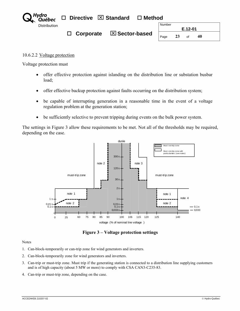
10.6.2.2 Voltage protection
Voltage protection must
• offer effective protection against islanding on the distribution line or substation busbar load;
• offer effective backup protection against faults occurring on the distribution system;
• be capable of interrupting generation in a reasonable time in the event of a voltage regulation problem at the generation station;
• be sufficiently selective to prevent tripping during events on the bulk power system.
The settings in Figure 3 allow these requirements to be met. Not all of the thresholds may be required, depending on the case.
80 908575 106 115 125 140
0,15 s
2 s
120 s
300 s
must-trip zone
voltage (% of nominal line voltage )
durée
120
30 s
Must -not-trip zone
25
1 s
0
0,15 s
1 s
0,1 s0,033 s
0,1 s0,033
Must -not-trip zone with particularities (see notes)
must-trip zone
note 4note 1
note 2 note 3
note 1
note 20,1 s
note 2
60 100
Figure 3 – Voltage protection settings
Notes
1. Can-block-temporarily or can-trip zone for wind generators and inverters.
2. Can-block-temporarily zone for wind generators and inverters.
3. Can-trip or must-trip zone. Must trip if the generating station is connected to a distribution line supplying customers and is of high capacity (about 5 MW or more) to comply with CSA CAN3-C235-83.
4. Can-trip or must-trip zone, depending on the case.
Directive ⌧ Standard Method Number
E.12-01 Corporate ⌧ Sector-based
Page 24 of 40
ACCEDWEB 210207-02 © Hydro-Québec
A
10.7 Locking of protections
Protection settings must not be changed without written authorization by Hydro-Québec. Locking by means of passwords is acceptable to Hydro-Québec.
10.8 Protection study
The power producer must submit an engineer-approved protection study of its facilities to Hydro-Québec. The study must include the information specified in Appendix C of this standard. Commissioning of the generating station may not be authorized until Hydro-Québec and the power producer have agreed on acceptance of the protection study. In addition, protection study results may entail making certain modifications to the distributor’s system. Such modifications may delay authorization of commissioning.
In general, the final protection study, including the definitive settings, must be submitted to Hydro-Québec two months prior to the planned initial energizing of the generating station so that the study can be verified and any necessary corrections be made.
To carry out the protection study, Hydro-Québec shall provide, at the power producer’s request, the data needed to determine the required protection systems.
11 CONTROLGEAR
11.1 Voltage regulators
Synchronous generators, inverters that may control power factor, and double-fed induction generators must be equipped with voltage regulators (or other equivalent systems) and be able to supply or absorb reactive power in order to meet Hydro-Québec voltage regulation requirements (see Section 7.4.1). For wind power plants, refer to Section 12.2.
11.2 Speed governors (synchronous generators)
To help regulate frequency on the power system, any generating unit with a nominal power rating of more than 10 MW must be equipped with a speed governing system with a permanent droop (sigma) adjustable, as a minimum, from 0% to 5% and no frequency dead band. For generating units with a nominal power rating of 10 MW or less, Hydro-Québec does not require, unless otherwise specified, that generating units be equipped with speed governors. When a speed governor is installed and is not required by Hydro-Québec, it must be disabled (frequency-controlled speed regulation must be switched off) when the generating unit is synchronized with the distribution system to reduce the risk of islanding. Use of the speed governor during generation that is synchronized with the distribution system may require the use of a transfer trip function to ensure separation of the generating station from the system.

Directive ⌧ Standard Method Number
E.12-01 Corporate ⌧ Sector-based
Page 25 of 40
ACCEDWEB 210207-02 © Hydro-Québec
A
11.3 Generating station synchronization with the Hydro-Québec system
The voltage level at which the synchronization operation can be executed depends on the capacity of the power producer facilities and the characteristics of the Hydro-Québec system. To prevent tripping of the rapid phase protection system on the Hydro-Québec circuit breaker involved when power producer transformers are energized, the power producer may need to energize its transformers before synchronizing with the Hydro-Québec system. The maximum capacity of the transformers that can be energized by the Hydro-Québec system (once service is restored) is established based on several factors. In general, at 25 kV, the maximum value is about 5 MVA.
Hydro-Québec shall inform the power producer of the voltage level at which the synchronization operation is to be performed.
11.3.1 Synchronous generators
Synchronization to the distribution system must be done using a generator synchronism check system (function 25). Hydro-Québec does not define the synchronization parameters, such as the fit between generator speed, phase angle or voltage amplitude. However, the level of voltage disturbance at the connection point must comply with Standard C.22-03 (see Section 7.1).
11.3.2 Induction generators
Induction generators must be synchronized to the Hydro-Québec system when they are close to their rated speed. Hydro-Québec does not define the synchronization parameter, which in this case is the fit between generator speed and its rated speed. However, the level of voltage disturbance at the connection point must comply with Standard C.22-03 (see Section 7.1).
The power producer must design its facilities so that generating station transformers can be energized by the Hydro-Québec system without tripping Hydro-Québec line protection.
11.3.3 Inverters
Hydro-Québec does not specify the synchronization parameters. However, the level of voltage disturbance at the connection point must comply with Standard C.22-03 (see Section 7.1).
The power producer must design its facilities so that generating station transformers can be energized by the Hydro-Québec system without tripping Hydro-Québec line protection.
12 SPECIFIC REQUIREMENTS FOR WIND GENERATION
Specific requirements are needed to cover additional technical aspects specific to wind energy technology. They add to or modify those already set out in this standard. They ensure that, during a disturbance on the transmission system, the wind power plant will contribute to maintaining bulk power system stability and to restoring system voltage and frequency.

Directive ⌧ Standard Method Number
E.12-01 Corporate ⌧ Sector-based
Page 26 of 40
ACCEDWEB 210207-02 © Hydro-Québec
A
12.1 Requirements during undervoltage conditions and low-voltage ride-through (LVRT)
Unless otherwise indicated by Hydro-Québec, any wind generator with a capacity equal to or exceeding 1 MW must be designed, built and operated so as to remain in service without tripping, directly or indirectly, for the zone above the line plotted in Figure 4. For voltage protection settings, refer to Figure 3.
Figure 4 – LVRT characteristic of wind generators of 1 MW or more Note: The amplitude represents the phase-to-ground voltage as a percentage of the nominal voltage of the system to
which the wind power plant is connected.
12.2 Voltage regulation
Unless otherwise indicated by Hydro-Québec, any wind power plant with a capacity exceeding 5 MW must be designed to supply or absorb, at the power plant output (system side), reactive power equivalent to an overexcited or underexcited nominal power factor less than or equal to 0.95 (see Section 7.4). In some cases, it may be required for the power plant to be designed to operate at a nominal power factor as low as 0.9 or reduce active power production to meet requirements of standard CSA/ACNOR CAN3-C235-83.
100%
Time (s)
Voltage ( see note )
0 30
90%
75%
50%
25%
85%
21 0.15 0

Directive ⌧ Standard Method Number
E.12-01 Corporate ⌧ Sector-based
Page 27 of 40
ACCEDWEB 210207-02 © Hydro-Québec
A
12.3 Frequency control (inertial response) Wind power plants with a rated capacity exceeding 10 MW must be equipped with a frequency control system. That system must be in continuous service but only act when major frequency deviations occur. It must not be used for frequency control purposes under steady-state conditions.
The purpose of the system is to have wind power plants participate in frequency restoration and thus maintain the present level of transmission system performance during major disturbances.
To achieve this, the system must reduce large, short-duration frequency deviations at least as much as does the inertial response of a conventional synchronous generator whose inertia (H) equals 3.5 s. This target performance is met, for instance, when the system varies the real power dynamically and rapidly by a minimum of about 5% for about 10 s when a large, short-duration frequency deviation occurs on the power system.
Unless otherwise indicated by Hydro-Québec, its use during generation requires a transfer trip function to ensure separation of the wind power plant from the system.
For wind power plants whose rated capacity is less than or equal to 10 MW, use of a frequency control system is prohibited (see Section 11.2).
12.4 Requirement during frequency variations
Unless otherwise indicated by Hydro-Québec, any wind generator of 1MW or more must be designed in a way that, when disturbances occur, it could be capable to remain in service during a system frequency variation of ±4 Hz/second.
12.5 Maximum up- and down-ramp rates
Unless otherwise indicated by Hydro-Québec, wind power plants with a rated capacity of 1 MW or more must be designed to comply with the following power-up and power-down ramp rates:
• Ramp up in an adjustable 2 to 60 minutes minimum from 0 MW (stopped) to Pmax (maximum power plant output)
• Ramp down in an adjustable 2 to 60 minutes minimum from Pmax (maximum power plant output) to 0 MW (stopped)
This requirement is intended to allow adequate operation of power system voltage regulators. It avoids too great a loss of wind generation at times of day when the load is rising rapidly and too great a rise in wind generation at other times of day when the load is falling rapidly.

Directive ⌧ Standard Method Number
E.12-01 Corporate ⌧ Sector-based
Page 28 of 40
ACCEDWEB 210207-02 © Hydro-Québec
A
12.6 Requirements regarding wind generator shutdown under forecast very low temperatures or high-wind conditions
Unless otherwise indicated by Hydro-Québec, wind power plants with a rated capacity of 1 MW or higher must be designed so they can gradually shut down completely over a minimum of 1 to 4 hours when the transmission provider forecasts ambient temperatures below the minimum for wind generator operation or forecasts winds of sufficient speed to entail wind generator shutdown.
13 ISLANDED GENERATION
In an effort to improve service continuity, Hydro-Québec may accept controlled use of islanded generation during major outages if technical and economic studies demonstrate the feasibility of such a mode of generation.
During the integration study, Hydro-Québec will inform the power producer of how the proposed generating station could help restore service on the distribution system.
If applicable, joint studies will be conducted to evaluate the feasibility of generation in islanded mode.
14 OFF-GRID GENERATION (BACKUP)
The power producer may supply its own loads while off grid.
15 RESPONSIBILITY FOR IMPLEMENTATION The Manager – System Orientations is responsible for implementing this standard.
16 RESPONSIBILITY FOR APPLICATION System planning managers are responsible for applying this standard.

Directive ⌧ Standard Method Number
E.12-01 Corporate ⌧ Sector-based
Page 29 of 40
ACCEDWEB 210207-02 © Hydro-Québec
A
APPENDIX A
Technical Information to be Transmitted to Hydro-Québec for the Distributed-Generation Plant Integration Study
Directive ⌧ Standard Method Number
E.12-01 Corporate ⌧ Sector-based
Page 30 of 40
ACCEDWEB 210207-02 © Hydro-Québec
A
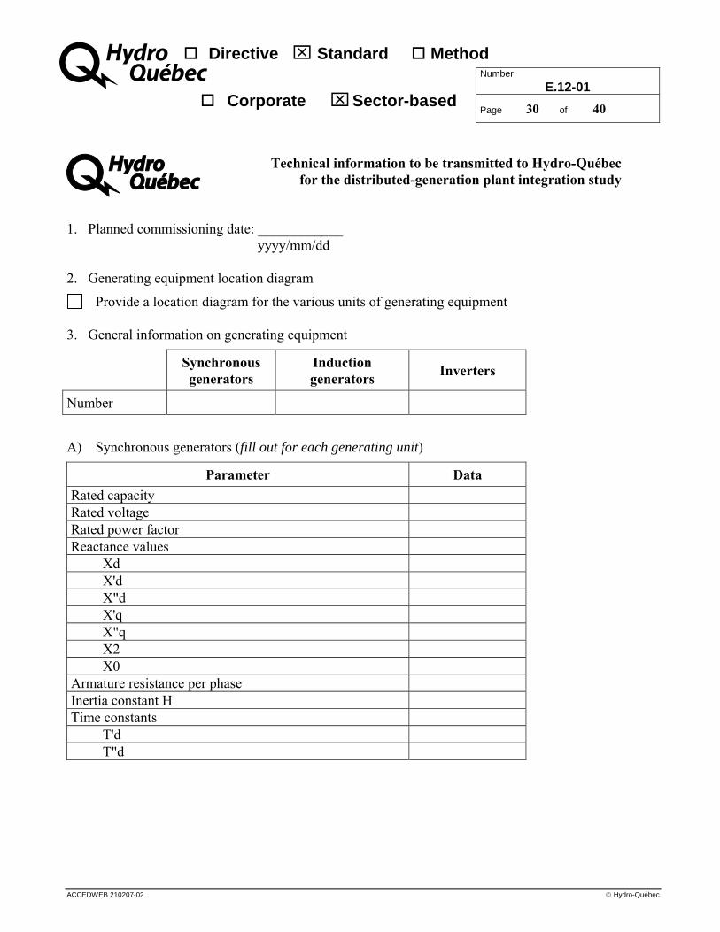
A Technical information to be transmitted to Hydro-Québec for the distributed-generation plant integration study
1. Planned commissioning date: ____________ yyyy/mm/dd
2. Generating equipment location diagram
Provide a location diagram for the various units of generating equipment 3. General information on generating equipment
Synchronous generators
Induction generators Inverters
Number
A) Synchronous generators (fill out for each generating unit)
Parameter Data Rated capacity Rated voltage Rated power factor Reactance values
Xd X'd X"d X'q X"q X2 X0
Armature resistance per phase Inertia constant H Time constants
T'd T"d

Directive ⌧ Standard Method Number
E.12-01 Corporate ⌧ Sector-based
Page 31 of 40
ACCEDWEB 210207-02 © Hydro-Québec
A
B) Induction generators (fill out for each generating unit)
Parameter Data Rated capacity Rated voltage Rated power factor
100% of rated power 75% of rated power 50% of rated power
Impedance values Xs Rs Xr Rr Xm (magnetizing reactance) X"d X0
Inertia constant H Time constant
T"d C) Inverters (fill out for each generating unit)
Parameter Data Energy source (solar, natural gas, biomass, etc.) Rated active power Rated voltage Rated power factor
at 100% of rated power If adjustable, possible power factor variation range
Short-circuit capacity (peak amperes/duration) Startup current (peak amperes) UL 1741 certified (yes/no) IEEE C62.41 certified (yes/no) IEEE C37.90 certified (yes/no) IEEE C37.90.1 certified (yes/no) IEEE C37.90.2 certified (yes/no) CSA C22.2 No. 107.1-01 certified (yes/no)* Can operate off-grid (yes/no)
*Provide all other available certification.

Directive ⌧ Standard Method Number
E.12-01 Corporate ⌧ Sector-based
Page 32 of 40
ACCEDWEB 210207-02 © Hydro-Québec
A
D) Wind generators
For double-fed wind generators, direct-drive permanent-magnet generators, wind generators equipped with converters, etc.
Provide a detailed EMTP model that the Distributor can use in its dynamic simulation studies. 4. Operating mode of generating equipment
Constant power Peak shaving Other: ____________________________________________________________________
5. Transformers
When transformers are used between the generating equipment and connection point, the following information must be provided to Hydro-Québec for each transformer:
Rated power and voltage Positive and zero-phase sequence impedances Winding resistance Primary and secondary winding connection
6. Target annual generation profile
Average monthly values for a typical year
January kW May kW September kW February kW June kW October kW March kW July kW November kW April kW August kW December kW
7. Single-line diagram of the proposed facility
Provide a complete single-line diagram of the electrical installation. 8. Control and protection diagram
Provide a control and protection diagram.
9. Generation will be used in emergency (stand-alone) mode
Yes
No

Directive ⌧ Standard Method Number
E.12-01 Corporate ⌧ Sector-based
Page 33 of 40
ACCEDWEB 280403-02 © Hydro-Québec
A
APPENDIX B
Typical Connection and Protection Diagrams for Facilities

Directive ⌧ Standard Method Number
E.12-01 Corporate ⌧ Sector-based
Page 34 of 40
ACCEDWEB 280403-02 © Hydro-Québec
A
Hydro-Québec metering on primary or secondary
(depending on commercial agreement)
25
Impedance required in certain instances
Connection point
Protection functions
25 ̶ Synchronization27 ̶ Undervoltage50 ̶ Overcurrent51 ̶ Delayed overcurrent59 ̶ Overvoltage81O ̶ Overfrequency81U ̶ Underfrequency
ImpedanceIf needed
Hydro-Québec
Power producer
3
59 81 O/U27
52
3
1-233
System for protecting the Hydro-Québec power system
21 51V
Required in certain instances
50/51
13
50N/51N
94
1
Auxiliary services
Hydro-Québec overhead service connection
Power producer connection
Synchronization required depending on technology used for power production
Isolation point
Disconnecting device required for metering on primary or
secondary (Standard F.22-01)
Figure 5 – MV overhead-overhead connection, maximum capacity of 5 MW

Directive ⌧ Standard Method Number
E.12-01 Corporate ⌧ Sector-based
Page 35 of 40
ACCEDWEB 280403-02 © Hydro-Québec
A
Hydro-Québec metering
Impedance required in certain instances
Connection point
Protection functions
25 ̶̶ Synchronization27 ̶̶ Undervoltage50 ̶̶ Overcurrent51 ̶̶ Delayed overcurrent59 ̶̶ Overvoltage81O ̶̶ Overfrequency81U ̶̶ Underfrequency
ImpdeanceIf needed
Hydro-Québec
Power producer
3
59 81 O/U27
52
3
233
System for protecting the Hydro-Québec power system
21 51V
Required in certain instances
50/51
1350N/51N
94
Hydro-Québec overhead service connection
Power producer connection
25
1
Auxiliary services
Synchronization required depending on technology used for
power production
Disconnecting device required for metering on
primary or secondary (Standard F.22-01)
Isolation point
Figure 6 – MV overhead-overhead connection, capacity exceeding 5 MW

Directive ⌧ Standard Method Number
E.12-01 Corporate ⌧ Sector-based
Page 36 of 40
ACCEDWEB 280403-02 © Hydro-Québec
A
Hydro-Québec metering on primary or secondary
(depending on commercial agreement)
25
Impedance required in certain instances
Connection point
Protection functions
25 ̶ Synchronization27 ̶ Undervoltage50 ̶ Overcurrent51 ̶ Delayed overcurrent59 ̶ Overvoltage81O ̶ Overfrequency81U ̶ Underfrequency
ImpedanceIf needed
Hydro-Québec
Power producer
3
59 81 O/U27
52
3
1-233
System for protecting the Hydro-Québec power system
21 51V
Required in certain instances
Synchronization required depending on technology used for power production
50/51
13
50N/51N
94
1
Hydro-Québec overhead service connection
Power producer connection
Auxiliary services
Isolation point
Disconnecting device required for metering on
primary or secondary (Standard F.22-01)
Figure 7 – MV overhead-underground connection, maximum capacity of 5 MW

Directive ⌧ Standard Method Number
E.12-01 Corporate ⌧ Sector-based
Page 37 of 40
ACCEDWEB 280403-02 © Hydro-Québec
A
Hydro-Québec metering on primary or secondary (depending
on commercial agreement)
25
Impedance required in certain instances
Connection point
Protection functions
25 - Synchronization27 - Undervoltage50 - Overcurrent51 - Delayed overcurrent59 - Overvoltage81O - Overfrequency81U - Underfrequency
ImpedanceIf required
Hydro-Québec
Power producer
3
5981
O/U27
52
3
1-233
System for protecting the Hydro-Québec power system
21 51V
Sometimes required
50/51
13
50N/51N
94
1
Hydro-Québec service connection
Power producer connection
Auxiliary services
Switching substation available at all times
Synchronization required depending on technology used for power production
Isolation point
Disconnecting device required for metering at primary or
secondary (Standard F.22-01)
Figure 8 – MV underground-underground connection, maximum capacity of 5 MW

Directive ⌧ Standard Method Number
E.12-01 Corporate ⌧ Sector-based
Page 38 of 40
ACCEDWEB 280403-02 © Hydro-Québec
A
APPENDIX C
Content of Power Producer Protection Studies

Directive ⌧ Standard Method Number
E.12-01 Corporate ⌧ Sector-based
Page 39 of 40
ACCEDWEB 280403-02 © Hydro-Québec
A
CONTENT OF POWER PRODUCER PROTECTION STUDY
The power producer must submit to Hydro-Québec a protection study containing the information specified in this appendix. This will allow Hydro-Québec to determine, as quickly as possible, whether the protection systems installed at the generating station will meet its system protection needs. Section 1: Introduction • Brief description of the site, project and Hydro-Québec system
• Specific details about the project (additional protection, specific setpoints, etc.)
• Future developments (additional capacity) Section 2: Characteristics of the facilities and Hydro-Québec system • Single-line diagram of generating station facilities
• Electrical characteristics of transformers, generating equipment and protection systems – Generators – Inverters, converters and other power electronics equipment – Transformers – Circuit breakers (more specifically the main circuit breaker) – Grounding resistors or reactors – Protection relays – Measurement transformers for protection systems – Excitation systems – Turbine and generator inertia constants in kg•m2 or in MW•s/MVA
Note A copy of the main characteristics from the manufacturer’s manual or technical specifications is desirable (except for relays accepted by Hydro-Québec).
• Characteristics of the Hydro-Québec system – Single-line diagram of the line (with conductor characteristics) – Single-line diagram of the substation – Hydro-Québec protection system tripping curves and their operating sequences – Single- and three-phase short-circuit levels at the Hydro-Québec substation busbar – Any information relevant to the study

Directive ⌧ Standard Method Number
E.12-01 Corporate ⌧ Sector-based
Page 40 of 40
ACCEDWEB 280403-02 © Hydro-Québec
A
Section 3: Fault calculation and analysis • Evaluation of grounding impedance
• Calculation of 3-Φ, Φ-to-ground and Φ-to-ground (Rf = 13.3 Ω) – At the generating station primary bus – At the generating station secondary bus – At the Hydro-Québec substation bus – At a single-phase connection near the generating station – At the point on the line farthest from the generating station – Downstream of the power system circuit breaker (if any)
Note Fault calculations must take the following into account:
Both Hydro-Québec and generating station contribution (with maximum and minimum operation of the generating equipment)
Contribution of the power plant alone The results must be presented in the form of a table. It is recommended that example calculations be provided.
• Verification of fuse coordination with proposed settings Section 4: Relay settings and coordination curves • Table showing the proposed settings for protective relays for protecting the Hydro-Québec system
along with their operating time for the faults to be studied
• Protection coordination curves
• Protection and control (or logic) diagrams Appendix 1: Monthly generation forecasts (capacity) Appendix 2: Calculation of flicker at point of common coupling (if required) Appendix 3: Calculation of harmonics at point of common coupling (if required) Appendix 4: Protection settings for generating equipment and transformers