A Human Factors Evaluation of a Methodology for ...
146
NASA/TM--2000-209764 A Human Factors Evaluation of a Methodology for Pressurized Crew Module Acceptability for Zero- Gravity Ingress of Spacecraft Merri J. Sanchez, PhD Lyndon B. Johnson Space Center, Houston, Texas March 2000
Transcript of A Human Factors Evaluation of a Methodology for ...
NASA/TM--2000-209764
A Human Factors Evaluation of a Methodology for
Pressurized Crew Module Acceptability for Zero-
Gravity Ingress of Spacecraft
Merri J. Sanchez, PhD
Lyndon B. Johnson Space Center, Houston, Texas
March 2000
TheNASASTIProgramOffice...in Profile
Sinceitsfounding,NASAhasbeendedicatedtotheadvancementof aeronauticsandspacescience.TheNASAScientificandTechnicalInformation(STI)ProgramOfficeplaysakeypartinhelpingNASAmaintainthis importantrole.
TheNASASTIProgramOfficeisoperatedbyLangleyResearchCenter,theleadcenterforNASA'sscientificandtechnicalinformation.TheNASASTIProgramOfficeprovidesaccesstotheNASASTIDatabase,thelargestcollectionofaeronauticalandspacescienceSTI in theworld.TheProgramOfficeisalsoNASA'sinstitutionalmechanismfor disseminatingtheresultsof itsresearchanddevelopmentactivities.TheseresultsarepublishedbyNASAin theNASASTIReportSeries,whichincludesthefollowingreporttypes:
* TECHNICALPUBLICATION.Reportsof completedresearchoramajorsignificantphaseof researchthatpresenttheresultsofNASAprogramsandincludeextensivedataortheoreticalanalysis.Includescompilationsofsignificantscientificandtechnicaldataandinformationdeemedto beof continuingreferencevalue.NASAcounterpartof peer-reviewedformalprofessionalpapers,buthavinglessstringentlimitationsonmanuscriptlengthandextentof graphicpresentations.
* TECHNICALMEMORANDUM.
Scientific and technical findings that are
preliminary or of specialized interest, e.g., quick
release reports, working papers, and
bibliographies that contain minimal annotation.
Does not contain extensive analysis.
* CONTRACTOR REPORT. Scientific
and technical findings by NASA-sponsored
contractors and grantees.
* CONFERENCE PUBLICATION.
Collected papers from scientific and technical
conferences, symposia, seminars, or other
meetings sponsored or co-sponsored by NASA.
* SPECIAL PUBLICATION. Scientific,technical, or historical information from NASA
programs, projects, and missions, often
concerned with subjects having substantial
public interest.
* TECHNICAL TRANSLATION.
English-language translations of foreign
scientific and technical material pertinent toNASA's mission.
Specialized services that complement the STI
Program Office's diverse offerings includecreating custom thesauri, building customized
databases, organizing and publishing research
results ... even providing videos.
For more information about the NASA STI
Program Office, see the following:
* Access the NASA STI Program HomePage at http://www.sti.nasa.gov
* E-mail your question via the Internet to
* Fax your question to the NASA STIHelp Desk at (301) 621-0134
/:# Telephone the NASA STI Help Desk at(301) 621-0390
Write to:
NASA STI Help Desk
NASA Center for AeroSpace Information7121 Standard Drive
Hanover, MD 21076-1320
NASA/TM--2000-209764
A Human Factors Evaluation of a Methodology for
Pressurized Crew Module Acceptability for Zero-
Gravity Ingress of Spacecraft
Merri J. Sanchez, PhD
Lyndon B. Johnson Space Center, Houston, Texas
National Aeronautics and
Space Administration
Lyndon B. Johnson Space CenterHouston, Texas 77058
March 2(K_0
ACKNOWLEDGMENTS
I am indebted to John Muratore for providing the resources to conduct the flight tests. Thanks
to Ann Bufkin, Carol Evans, Jeff Fox, Dale Jennings, Edward Robenson, Wayne Peterson, and David
Young for their help in designing and manufacturing the mockups, outfitting them with support
equipment, and gathering all the hardware required for the flight tests. Thanks to the many test
conductors who endured the rigors of parabolic flight to collect the data. Thanks to the astronauts and
medical evaluators who participated in the Delphi studies, the ground tests, and the flight tests. Thanks
to Mary Manley, who organized the hardware and flight test for the reduced volume tests, and thanks to
Dr. Elizabeth Walden for her work on the functional task analysis.
Available from:
NASA Center for AeroSpace Information
7121 Standard Drive
Hanover, MD 21076-1320
301-621-0390
National Technical Information Service
5285 Port Royal Road
Springfield, VA 22161703-605 -6000
This report is also available in electronic form at http://techreports.larc.nasa.gov/cgi-bin/NTRS.
ABSTRACT
The purpose of this research was to develop a methodology for evaluating the performance and
acceptability characteristics of the pressurized crew module volume suitability for zero-gravity (g)
ingress of a spacecraft. The methodology was tested by performing an evaluation of the operational
acceptability of the National Aeronautics and Space Administration (NASA) crew return vehicle (CRV)
for zero-g ingress of astronaut crew, volume for crew tasks, and the general crew module and seat layout.
This research is significant because no standard or methodology has ever been established for
evaluating volume acceptability in human spaceflight vehicles. Volume affects the astronauts' ability to
ingress and egress the vehicle, to maneuver in the vehicle, and to perform critical operational tasks inside
the vehicle. Much research has been conducted in the areas of aircraft ingress, egress, and rescue in
order to establish military and civil aircraft standards. However, due to the extremely limited number of
human-rated spacecraft, this topic has been unaddressed.
The NASA CRV was used for this study. The prototype vehicle can return a seven-member crew
from the International Space Station in the event of a medical or Station emergency. The vehicle's
internal arrangement must be designed to facilitate rapid zero-g ingress, zero-g maneuverability, ease of
one-g egress and rescue, and ease of operational tasks in multiple acceleration environments. A full-
scale crew module mockup was built and outfitted with representative adjustable seats, crew equipment,
and a volumetrically equivalent hatch.
Human factors testing of this mockup was conducted in three acceleration environments (zero g, one
g, and 1.8 g's) using ground-based facilities and the KC-135 aircraft. Performance and acceptability
measurements were collected. Data analysis was conducted using analysis of variance and
nonparametric techniques.
iii

iv
CONTENTS
Page
ACKNOWLEDGMENTS .................................................................................................................. ii
ABSTRACT ....................................................................................................................................... HI
Figures ............................................................................................................................................ viiTables ............................................................................................................................................. vii
ACRONYMS ..................................................................................................................................... vm
Chapter I INTRODUCTION ............................................................................................................. 1
1. I Background .............................................................................................................................. 2
1.2 Research Objectives ................................................................................................................ 5
Chapter 2 LITERATURE REVIEW .................................................................................................. 6
2.1 Need for Rapid Return to Earth ............................................................................................... 6
2.2 Rescue Vehicle Requirements ................................................................................................. 92.3 Crew Return Vehicle Medical Considerations ........................................................................ 9
2.4 Recent Development Efforts of Human Spacecraft ................................................................ I 12.5 Crew Events Inside the Crew Return Vehicle ......................................................................... 12
2.6 Related Applications ............................................................................................................... 15
2.7 Human Factors Considerations ................................................................................................ 16
2.7.1 Use of Mockups ................................................................................................................ 16
2.7.2 Anthropometry and Human Interfaces .............................................................................. 16
Chapter 3 METHODOLOGY ............................................................................................................ 183.1 Overview ................................................................................................................................. 18
3.2 Delphi Study ............................................................................................................................ 19
3.3 Participants .............................................................................................................................. 22
3.4 Apparatus ................................................................................................................................. 23
3.4.1 Phase 2 Unique Hardware ................................................................................................. 24
3.4.2 Phase 3 Unique Hardware ................................................................................................. 25
3.5 Experimental Design ............................................................................................................... 27
3.5.1 Independent Variables ...................................................................................................... 27
3.5.2 Dependent Variables ......................................................................................................... 27
3.6 Procedure ................................................................................................................................. 28
3.6.1 Phase 1 .............................................................................................................................. 28
3.6.2 Phases 2 and 3 ................................................................................................................... 29
3.7 Data Analysis ........................................................................................................................... 30
Chapter 4 RESULTS .......................................................................................................................... 32
4.1 Phase 1: Pilot Study ................................................................................................................ 32
4.1. I Results From Pilot Study .................................................................................................. 34
4.1.1.1 Zero-g Ingress and Egress .......................................................................................... 34
4.1.1.2 Seat Configuration ...................................................................................................... 344.1.1.3 Hatch .......................................................................................................................... 34
4.1.1.4 Handholds ................................................................................................................... 34
4.1.1.5 Crew Volume ............................................................................................................. 34
4.1.1.6 Helmets ....................................................................................................................... 34
4.1. 1.7 Constraints and Limitations ....................................................................................... 35
4.1.2 Application of Pilot Study Results ................................................................................... 35
CONTENTS(continued)
Page
4.2 Phase 2 ...................................................................................................................................... 35
4.2.1 Performance Variables ...................................................................................................... 35
4.2.2 Acceptability Variables .................................................................................................... 37
4.2.2. I Acceptability Results From Phase 2 Full Volume Tests ............................................ 37
4.2.2.2 Acceptability Results From Phase 2 Reduced Volume Tests .................................... 40
4.3 Phase 3 ..................................................................................................................................... 41
4.3. ! Performance Variables ...................................................................................................... 41
4.3.2 Acceptability Variables .................................................................................................... 43
4.3.2.1 Acceptability Analysis From Phase 3 ........................................................................ 43
4.3.2.2 Acceptability Results From Phase 3 ........................................................................... 5 I4.4 Differences Between Phases ................................................................................................... 58
Chapter 5 DISCUSSION .................................................................................................................... 605.1 Performance Variable Discussion ........................................................................................... 61
5.2 Acceptability Variable Discussion .......................................................................................... 61
5.2. ! Ingress/Egress ................................................................................................................... 61
5.2.2 Seating ............................................................................................................................... 625.2.3 Hatch .................................................................................................................................. 62
5.2.4 Volume .............................................................................................................................. 63
5.2.5 Crew Equipment and Stowage .......................................................................................... 635.2.6 General .............................................................................................................................. 63
Chapter 6 CONCLUSIONS AND FURTHER STUDY .................................................................... 656.1 Conclusions ............................................................................................................................. 65
6.2 Further Study ........................................................................................................................... 65
REFERENCES ................................................................................................................................... 66
APPENDIX 1 7-Person KC-135 Flight Test Procedure .................................................................. 75
APPENDIX 2 7-Person KC-135 Flight Test Postflight Questionnaire ........................................... 93
APPENDIX 3 ANOVA Summary Tables ........................................................................................ 105
vi
CONTENTS(continued)
Figures!. CRV during reentry ..................................................................................................................
2. X-38 under parafoil flight ........................................................................................................
3. Top view of seating ..................................................................................................................4. Side view of crew module ........................................................................................................
5. Full vehicle layout ....................................................................................................................
6. Typical KC- 135 parabola .........................................................................................................
7. Crew module mockup outer shell .............................................................................................
8. Mockup seat and display layouts ..............................................................................................
9. Articulating seat detail .............................................................................................................
10. Interior of mockup with seats folded flat .................................................................................
I I. Soyuz-style seat ........................................................................................................................
!2. 22-deg wedge on starboard middle row seat ............................................................................
13. Taking measurements during 1.8-g portion of4-person mockup flight test ............................
14. Aided ingress of"unconscious" crew member during 4-person mockup flight test ................
15. Zero-g ingress into mockup ......................................................................................................
16. Middle row seats inside mockup ..............................................................................................
17. Preparing to close hatch in mockup .........................................................................................
18. Providing air and medical care to Rescue Randy .....................................................................
Tables
1. Fatalities, Near Fatalities, and Emergencies During Spaceflight .............................................2. Crew Size and Mass Limits ......................................................................................................
3. Functional Analysis of CRV ....................................................................................................
4. Characteristic Human Dimensions ...........................................................................................
5. Male and Female Dimensions ..................................................................................................
6. Delphi Participant Profiles .......................................................................................................
7. Delphi Sequence .......................................................................................................................
8. Participant Profiles ...................................................................................................................
9. Acceptability Measurements ....................................................................................................
10. ANOVA/2-values of Phase 2 Dependent Performance Variables ...........................................
1 !. Phase 2 Dependent Performance Variables Statistical Data ....................................................
12. ANOVA/2-values of Phase 3 Dependent Performance Variables ...........................................
13. Phase 3 Dependent Performance Variables Statistical Data ....................................................
14. ANOVA R-values of Phase 3 Dependent Acceptability Variables ..........................................
15. Phase 3 Dependent Acceptability Variables Statistical Data ...................................................
16. ANOVA p-values Comparing Phase 3 Subpopulation Dependent Acceptability Variables ..........
17. Phase 3 Parabola Overview ......................................................................................................
18. Seat Comfort Comparisons ......................................................................................................
19. ANOVA/2-values Comparing Phase 2 and Phase 3 Dependent Performance Variables .........
20. Single Factor ANOVA Summary of Phase 2 Dependent Performance Variables ...................
21. Single Factor ANOVA Summary of Phase 3 Dependent Performance Variables ...................
22. Single Factor ANOVA Summary of Phase 3 Dependent Acceptability Variables ..................
23. Single Factor ANOVA Summary of Phase 3 Subpopulation Dependent Acceptability Variables ....
Page
2
3
4
4
4
19
23
24
25
25
26
26
33
33
54
55
56
57
6
12
14
17
17
20
21
22
28
36
36
41
42
43
45
48
52
55
59
1(14
106
108
116
vii
AFB
AFSC
AGARD
ANOVA
cm
COs
CRV
CTV
deg
DH
DOD
DRM
ESA
fpsft
g
HRPPC
in
ISS
JSC
kg
LiOH
m
MIL
NAS
NASA
NASDA
NATO
am
O5
SAE
sec
STD
XCRV
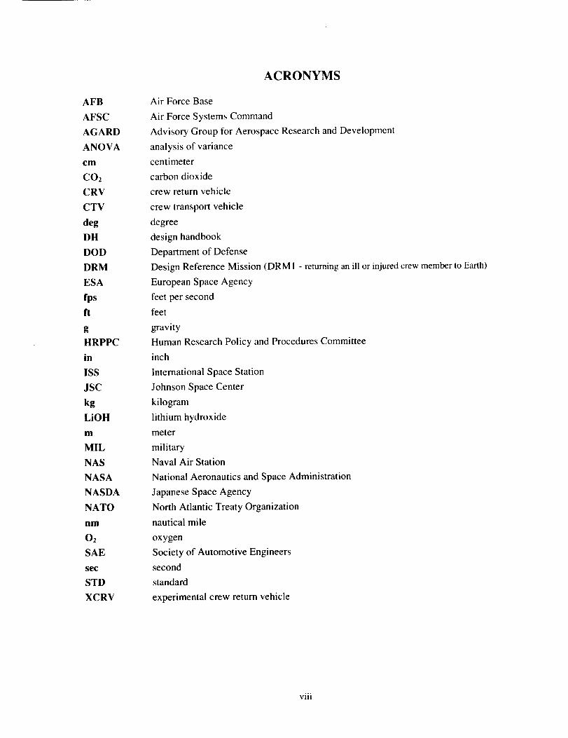
ACRONYMS
Air Force Base
Air Force Systems Command
Advisory Group for Aerospace Research and Development
analysis of variance
centimeter
carbon dioxide
crew return vehicle
crew transport vehicle
degree
design handbook
Department of Defense
Design Reference Mission (DRM 1 - returning an ill or injured crew member to Earth)
European Space Agency
feet per second
feet
gravity
Human Research Policy and Procedures Committee
inch
International Space Station
Johnson Space Center
kilogram
lithium hydroxide
meter
military
Naval Air Station
National Aeronautics and Space Administration
Japanese Space Agency
North Atlantic Treaty Organization
nautical mile
oxygen
Society of Automotive Engineers
second
standard
experimental crew return vehicle
VIII
Chapter 1
INTRODUCTION
The crew of a human spacecraft experiences an unusual set of conditions ranging from the high loads
of launch, to microgravity, to atmospheric entry, and landing. The costs of components to protect the
crew in these environments are high. These factors drive a critical review of every aspect of the design
of the crew station accommodations, far beyond what is practical or economical for Earth-based human
activities (Roebuck, 1993). The United States has used five human spaceflight vehicles, including
Mercury, Gemini, the Apollo Command Module, the Apollo Lunar Excursion Module, and the Space
Shuttle. To date, no established standard or methodology has been developed to evaluate the
acceptability of the pressurized crew module volume of any spacecraft (A. Nicogossian [Associate
Administrator, NASA Headquarters, personal communication, 1999]: R. Williams [Chief Medical
Officer, NASA Headquarters, personal communication, 1999]; L. Nicholson ]Director, Engineering, JSC,
personal communication, 1999]; and C. Berry [Apollo Flight Surgeon, Aerospace Medical Consultants,
personal communication, 1999]). Instead, the vehicles are designed and sized to minimize structure,
weight, volume, and to fit designated launch vehicles. This has left the pressurized volume available to
the crew to be an artifact of the volume left over after systems equipment is installed. Human factors are
the first compromise in spacecraft design, and are often not addressed until late in the design cycle.
This research effort focused on the development and testing of a methodology to evaluate the
acceptability of the pressurized crew module volume for zero-gravity (g) ingress of a spacecraft. This
research addressed both the short-term and long-term needs of crew module design and volume
acceptability. The methodology has worldwide applicability for the evaluation of the civilian and military
human spacecraft being designed by all space-faring nations. In the immediate future, the research will be
the basis of National Aeronautical and Space Administration (NASA) evaluations for new spacecraft.
NASA is currently prototyping the X-38 experimental crew return vehicle (XCRV) spacecraft for use
as a rescue vehicle for the International Space Station (ISS). This presents a unique opportunity to develop
a methodology for evaluating volume acceptability using the X-38 XCRV crew module as a test bed.
Human factors analysis and evaluations were conducted during this research activity to complement
the spacecraft design and development of the crew module. The XCRV design must meet the operational
requirements specified by the ISS Program. These design reference missions (DRMs) are documented in
SSP 41(_00, System Specification for the International Space Station, paragraph 3.2.1.1.7, and in SSP
50306, International Space Station (ISS) Crew Return Vehicle (CRV) Performance Requirements. There
are three DRMs that must be satisfied. These include:
I. Emergency medical return of an ill or injured crew person.
2. Return of the crew in the event that the ISS is not habitable (i.e., the ISS atmosphere has become
contaminated, the ISS cannot maintain internal pressure, the ISS cannot maintain attitude, or
critical ISS utilities have irrecoverably failed).
3. Return of the crew in the event that the ISS cannot be resupplied.
1.1 Background
The X-38 XCRV is currently being developed by NASA at the Johnson Space Center (JSC). After
delivery in the Shuttle's payload bay (uncrewed), the CRV will be berthed to the ISS via a tunnel adapter,
providing the capability to return up to seven crew members in a shirtsleeve environment to any landing
site in the world. An alternate interior configuration referred to as a crew transport vehicle (CTV) is
being developed by the European Space Agency (ESA) and will be launched on an Ariane 5 booster
(Moskwa, 1996). The CTV will be capable of transporting three crew members to orbit and returning up
to four crew members to Earth.
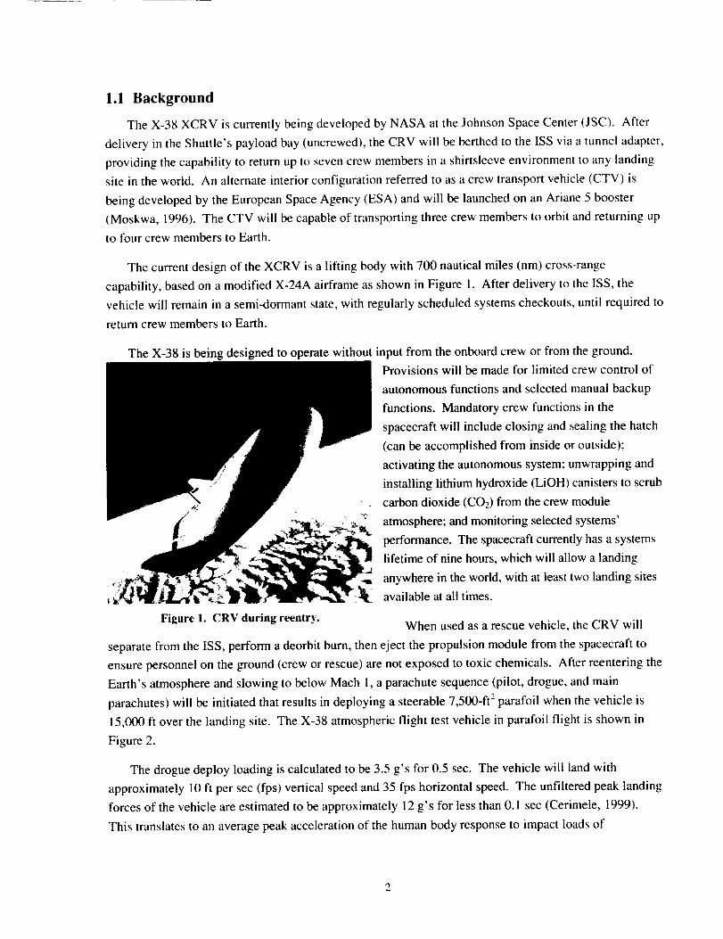
The current design of the XCRV is a lifting body with 700 nautical miles (nm) cross-range
capability, based on a modified X-24A airframe as shown in Figure 1. After delivery to the ISS, the
vehicle will remain in a semi-dormant state, with regularly scheduled systems checkouts, until required to
return crew members to Earth.
The X-38 is being designed to operate without input from the onboard crew or from the ground.
Figure 1. CRV during reentry.
Provisions will be made for limited crew control of
autonomous functions and selected manual backup
functions. Mandatory crew functions in the
spacecraft will include closing and sealing the hatch
(can be accomplished from inside or outside);
activating the autonomous system; unwrapping and
installing lithium hydroxide (LiOH) canisters to scrub
carbon dioxide (CO2) from the crew module
atmosphere; and monitoring selected systems'
performance. The spacecraft currently has a systems
lifetime of nine hours, which will allow a landing
anywhere in the world, with at least two landing sites
available at all times.
When used as a rescue vehicle, the CRV will
separate from the ISS, perform a deorbit burn, then eject the propulsion module from the spacecraft to
ensure personnel on the ground (crew or rescue) are not exposed to toxic chemicals. After reentering the
Earth's atmosphere and slowing to below Mach 1, a parachute sequence (pilot, drogue, and main
parachutes) will be initiated that results in deploying a steerable 7,500-ft 2 parafoil when the vehicle is
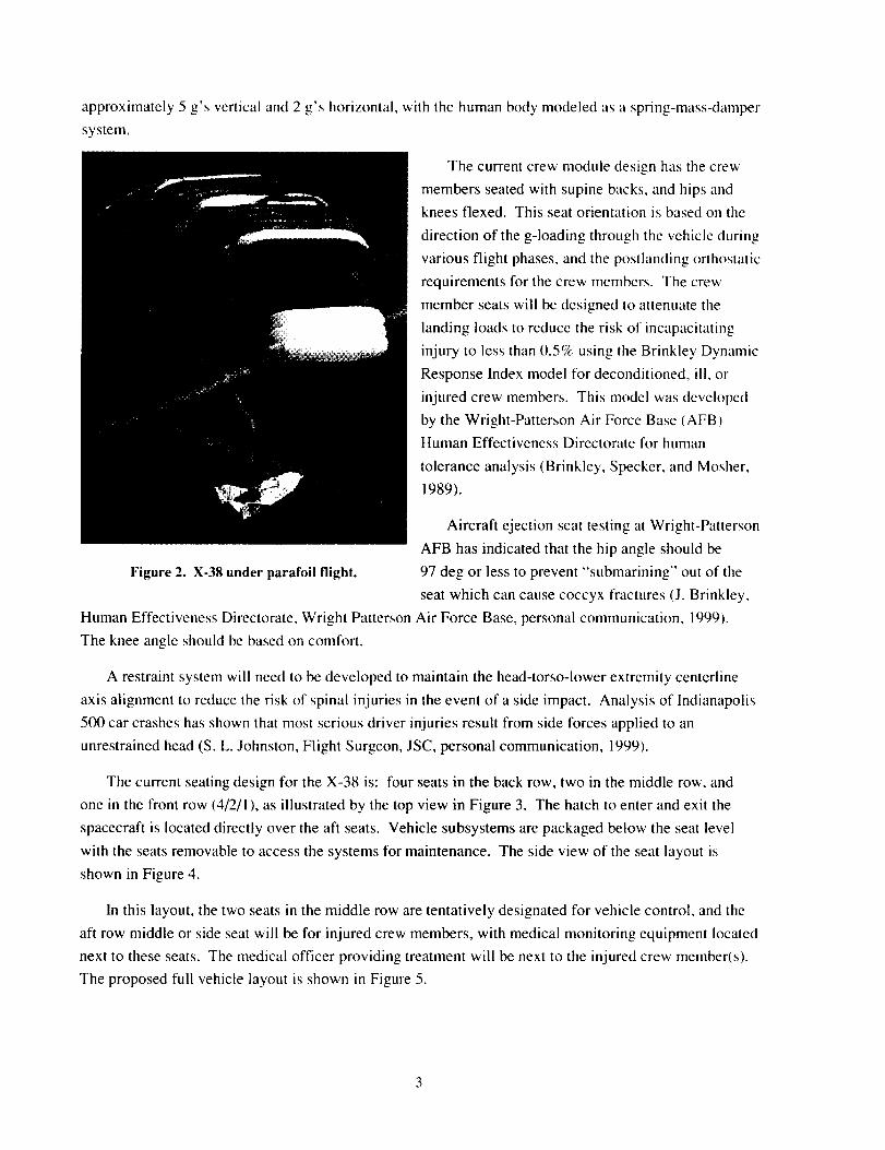
15,000 ft over the landing site. The X-38 atmospheric flight test vehicle in parafoil flight is shown in
Figure 2.
The drogue deploy loading is calculated to be 3.5 g's for 0.5 sec. The vehicle will land with
approximately 10 ft per sec (fps) vertical speed and 35 fps horizontal speed. The unfiltered peak landing
forces of the vehicle are estimated to be approximately 12 g's for less than 0.1 sec (Cerimele, 1999).
This translates to an average peak acceleration of the human body response to impact loads of
approximately5g's verticaland2g's horizontal,withthehumanbodymodeledasaspring-mass-dampersystem.
Thecurrentcrewmoduledesignhasthecrewmembersseatedwithsupinebacks,andhipsandkneesflexed.Thisseatorientationisbasedonthedirectionof theg-loadingthroughthevehicleduringvariousflightphases,andthepostlandingorthostaticrequirementsfor thecrewmembers.Thecrewmemberseatswill bedesignedto attenuatethelandingloadstoreducetheriskof incapacitatinginjury totessthan0.5c/cusingtheBrinkleyDynamicResponseIndexmodelfor deconditioned,ill, orinjuredcrewmembers.ThismodelwasdevelopedbytheWright-PattersonAir ForceBase(AFB)HumanEffectivenessDirectoratefor human
toleranceanalysis(Brinkley,Specker,andMosher,1989).
AircraftejectionseattestingatWright-PattersonAFBhasindicatedthatthehipangleshouldbe
Figure2. X-38under parafoil flight. 97 deg or less to prevent "submarining" out of the
seat which can cause coccyx fractures (J. Brinkley,
Human Effectiveness Directorate, Wright Patterson Air Force Base, personal communication, 1999).
The knee angle should be based on comfort.
A restraint system will need to be developed to maintain the head-torso-lower extremity centerline
axis alignment to reduce the risk of spinal injuries in the event of a side impact. Analysis of Indianapolis
500 car crashes has shown that most serious driver injuries result from side forces applied to an
unrestrained head (S. L. Johnston, Flight Surgeon, JSC, personal communication, 1999).
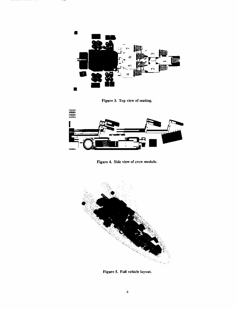
The current seating design for the X-38 is: four seats in the back row, two in the middle row, and
one in the front row (4/2/I), as illustrated by the top view in Figure 3. The hatch to enter and exit the
spacecraft is located directly over the aft seats. Vehicle subsystems are packaged below the seat level
with the seats removable to access the systems for maintenance. The side view of the seat layout is
shown in Figure 4.
In this layout, the two seats in the middle row are tentatively designated for vehicle control, and the
aft row middle or side seat will be for injured crew members, with medical monitoring equipment located
next to these seats. The medical officer providing treatment will be next to the injured crew member(s).
The proposed full vehicle layout is shown in Figure 5.
III
Figure 3. Top view of seating.
Figure 4. Side view of crew module.
Figure 5. Full vehicle layout.
1.2 Research Objectives
The primary purpose of this research was to develop a methodology to evaluate the pressurized crew
module volume suitability for zero-g ingress of spacecraft. The specific objectives of this study were to:
1. Determine the variables that should be used to develop an evaluation methodology through a
Delphi study.
2. Develop an appropriate methodology to evaluate the crew module volume suitability for zero-g
ingress by addressing the variables determined from the Delphi study.
3. Conduct ground and inflight evaluations to verify the methodology.
The research included collecting performance and acceptability measurements. In order to develop
the methodology, the research addressed the major design issues affecting ingress, egress, and rescue.
This included hatch stowage location, seat arrangement, location of equipment that needs to be installed
in the crew usable volume, and operational tasks that must be performed.
As evidenced from the literature search that follows, there is a need for a methodology to determine
acceptable spacecraft volumes based on ingress, egress, and layout. The X-38 is the first human-rated
spacecraft to be designed, built, and flown since the Space Shuttle, which first flew in 1982, and provides
a unique opportunity to develop and use a human factors evaluation methodology. The only other
human-rated spacecraft in operation today is the Russian Soyuz, which was first flown in 1967, and has
serious human factors limitations.
This research provides a unique contribution to the state of the art and the body of knowledge of
spacecraft design by developing a standard methodology for determining acceptable and functional
spacecraft volumes. The methodology can be used during the design and evaluation of all civil and
military human spacecraft developed by all nations. In addition, critical information was determined on
anthropometric fit and function evaluations of the seats and equipment layout, and ingress.
Chapter 2LITERATURE REVIEW
A literature review was conducted to understand the state of the art of human factors evaluations of
spacecraft, focusing on volume, ingress, egress, and rescue issues. This review was expanded to include the
related areas of aircraft and escape pods from oil platforms. All these vehicles are required to allow for rapid
ingress and egress, access for rescue, and to sustain life in a closed environment. Automobiles were also
considered, which are required to accommodate a large anthropometric range in population. General human
factors issues of the use of mockups for testing and how anthropometry affects analysis were also reviewed.
2.1 Need for Rapid Return to Earth
It has always been recognized that spaceflight is dangerous, and the hazards are unique from both
environmental and high-performance vehicle perspectives. A conscious effort has been made to address these
issues throughout the history of human spaceflight, but that work has mainly focused on safety, and not
necessarily on general human factors and optimizing the interfaces for equipment and spacecraft operation.
Among the various world space programs, astronauts have died on the ground, during ascent, and
during reentry. There have been multiple life-threatening launch aborts, aborts in orbit, and aborted
reentry attempts. And within the past two years the Russian space station Mir suffered two of the events
most feared by crew members on orbit: (I) a fire in the space station; and (2) a collision with another
spacecraft resulting in a module depressurization. With almost 400 cosmonauts and astronauts flying in
space to date, there have been 14 fatalities from four events, and multiple other events that could have
been fatal. These are shown in Table 1 (Swenson, 1966; Hacker, 1977; Turnhill, 1978; Brooks, 1979;
Oberg, 1981: Kane, 1984; Furniss, 1986; Fabian, 1988; Phillip, 1988; Compton, 1989; Severin, 1991;
Burrough, 1998; Lucid, 1998; C. R. Justiz, 1999 ]Research Pilot, Aircraft Operations Safety Officer,
JSC, personal communication]: and Oberg, 1999).
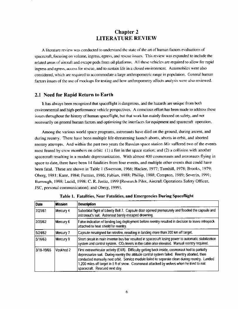
Table 1. Fatalities, Near Fatalities, and Emergencies During Spaceflight
Date
7/21/61
2/20/62
5/24/62
5/16/63
3118-19/65
Mission
Mercury 4
Mercury6
Mercury 7
Mercury9
Voskhod 2
Description
Suborbital flight of LibertyBell 7. Capsule door opened prematurely and floodedthe capsule andastronaut's suit. Astronaut barely escaped drowning.
False indication of landing bag deployment before reentry resulted in decision to leave retropackattached to heat shield for reentry.
Capsule misalignedfor retrofire,resultingin landing more than 200 km off target.
Short circuit in main inverterbus bar resulted in spacecraft losing power to automatic stabilization
system and control system. CO2 levels in the cabin also elevated. Manual reentry required.
First extravehicular activity (EVA). Difficulty getting back inside, cosmonaut had to partially
depressurize suit. During reentry the attitude control system failed. Reentry aborted, then
conducted manually next orbit. Service module failed to separate clean during reentry. Landed
1,200 miles off target in 5 ft of snow. Cosmonaut attacked by wolves when he tried to exit
spacecraft. Rescued next day.
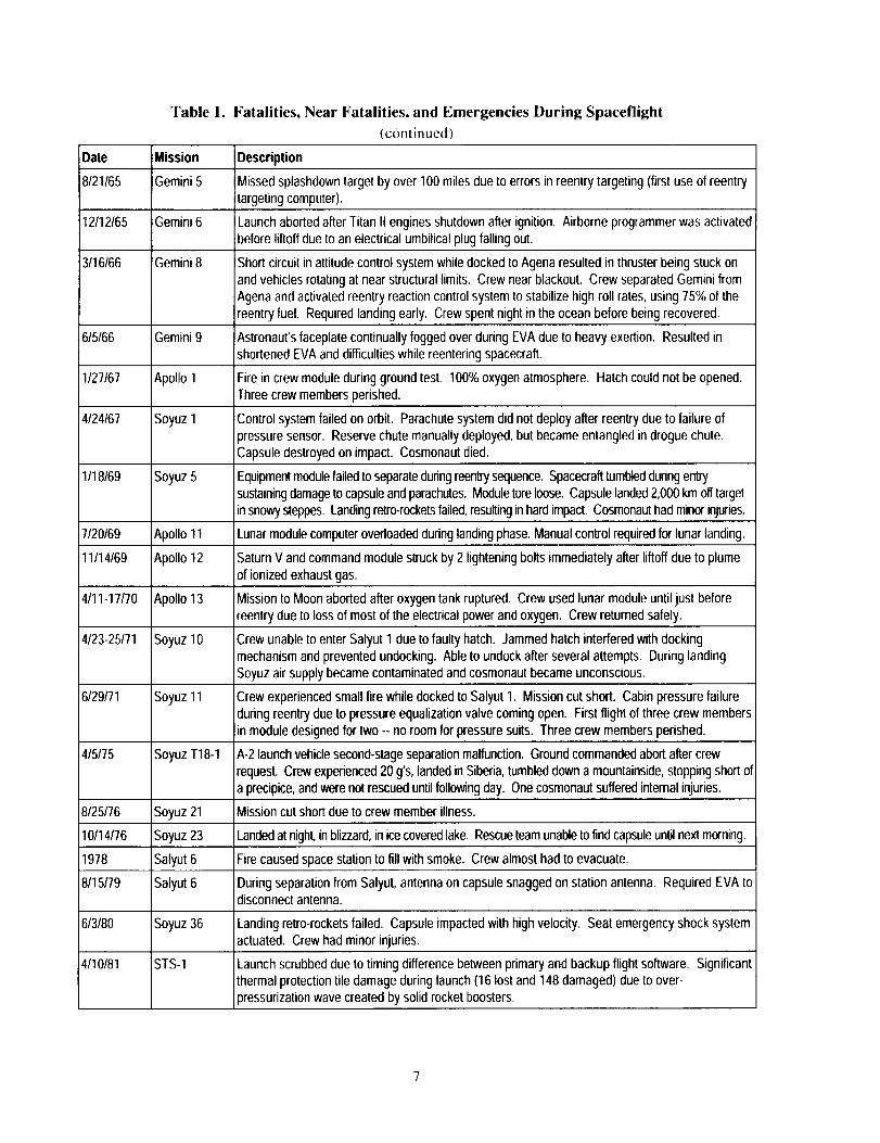
Table 1. Fatalities, Near Fatalities, and Emergencies During Spaceflight
(continued)
Date Mission
8121165 IGemini 5
12/12/65
3116166
6/5/66
1127167
4124167
1/18/69
iGemini 6
'Gemini 8
Gemini 9
Apollo 1
Soyuz I
Soyuz 5
Description
Missed splashdown target by over 100 miles due to errors in reentry targeting (first use of reentrytargeting computer).
Launch aborted after Titan II engines shutdown after ignition. Airborne programmer was activatedbefore liftoff due to an electrical umbilical plug falling out.
Short circuit in attitude control system while docked to Agena resulted in thruster being stuck on
and vehicles rotating at near structural limits. Crew near blackout. Crew separated Gemini from
Agena and activated reentry reaction control system to stabilize high roll rates, using 75% of thereentry fuel. Required landing early. Crew spent night in the ocean before being recovered.
Astronaut's faceplate continually fogged over during EVA due to heavy exertion. Resulted inshortened EVA and difficulties while reentering spacecraft.
Fire in crew module during ground test. 100% oxygen atmosphere. Hatch could not be opened.Three crew members perished.
Control system failed on orbit. Parachute system did not deploy after reentry due to failure of
pressure sensor. Reserve chute manually deployed, but became entangled in drogue chute.
Capsule destroyed on impact. Cosmonaut died.
Equipmentmodulefailed to separate dudngreen_ sequence. Spacecraft tumbled during entry
sustainingdamage to capsule and parachutes. Moduletore loose. Capsule landed2,000 km off target
in snowy steppes. Landing retro-rocketsfailed,resultingin hard impact. Cosmonauthad minor injuries.
7/20/69 Apollo 11 Lunar module computer overloaded during landing phase. Manual control required for lunar landing.
11/14/69 Apollo 12 Saturn V and command module struck by 2 lightening bolts immediately after liftoff due to plume
of ionized exhaust gas.
4/11-17/70 Apollo 13 Mission to Moon aborted after oxygen tank ruptured. Crew used lunar module until just beforereentry due to loss of most of the electrical power and oxygen. Crew returned safely.
4/23-25/71 Soyuz 10 Crew unable to enter Salyut 1 due to faulty hatch. Jammed hatch interfered with dockingmechanism and prevented undocking. Able to undock after several attempts. During landing
Soyuz air supply became contaminated and cosmonaut became unconscious.
6129171 Soyuz 11 Crew experienced small fire while docked to Salyut 1. Mission cut short. Cabin pressure failureduring reentry due to pressure equalization valve coming open. First flight of three crew members
in module designed for two -- no room for pressure suits. Three crew members perished.
4/5/75 Soyuz T18-1 A-2 launch vehicle second-stage separation malfunction. Ground commanded abort after crewrequest. Crew experienced 20 g°s,landed in Siberia, tumbled down a mountainside, stopping short of
a precipice, and were not rescued until following day. One cosmonaut suffered internal injuries.
8/25/76 Soyuz 21 Mission cut short due to crew member illness.
10/14/76 Soyuz 23 Landed at night, in blizzard, in ice coveredlake. Rescueteam unable to find capsule until next morning.
1978 Salyut 6 Fire caused space station to fill with smoke. Crew almost had to evacuate.
8/15179 Salyut 6 During separation from Salyut, antenna on capsule snagged on station antenna. Required EVA todisconnect antenna.
6/3/80 Soyuz 36 Landing retro-rockets failed. Capsule impacted with high velocity. Seat emergency shock systemactuated. Crew had minor injuries.
4/10/81 STS-I Launch scrubbed due to timing difference between primary and backup flight software. Significantthermal protection tile damage during launch (16 lost and 148 damaged) due to over-
pressurization wave created by solid rocket boosters.
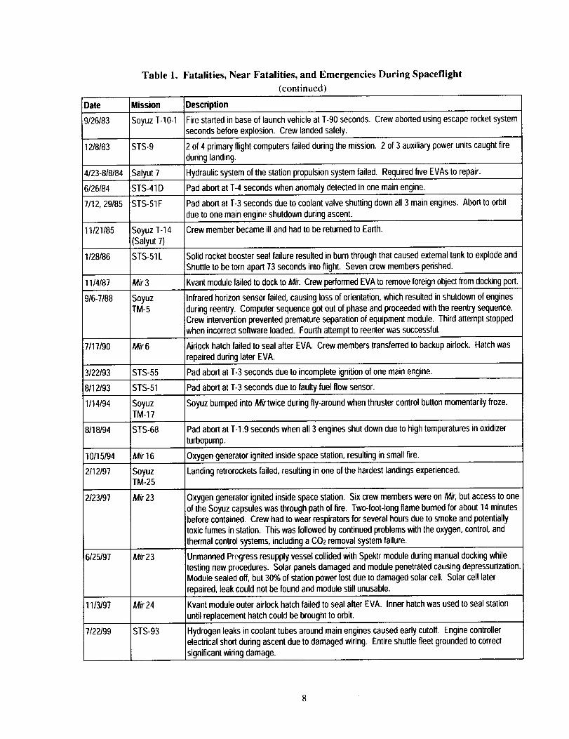
Table 1. Fatalities, Near Fatalities, and Emergencies During Spaceflight
(continued)
Date
_9/26/83
1218183
Mission
Soyuz T-10-1
STS-9
Description
Fire started in base of launch vehicle at T-90 seconds. Crew aborted using escape rocketsystem
seconds before explosion. Crew landed safely.
2 of 4 primary flightcomputers failed during the mission. 2 of 3 auxiliary power unitscaught fire
during landing.
4123-818184 Salyut 7 Hydraulic system of the station propulsion system failed. Required five EVAs to repair.
6126184 STS-41 D Pad abort at T-4 seconds when anomaly detected in one main engine.
7/12, 29185 STS-51 F Pad abort at T-3 seconds due to coolant valve shutting down all 3 main engines. Abort to orbit
due to one main engine shutdown during ascent.
11/21/85 Soyuz T-14 Crew member became ill and had to be returned to Earth.
(Salyut 7)
1128186 STS-51L Solid rocket booster seal failure resulted in burn through that caused external tank to explode and
Shuttle to be torn apart 73 seconds into flight. Seven crew members perished.
11/4/87 Mir3 Kvant module failed to dock to Mir. Crew performed EVAto remove foreign object from docking port.
9/6-7/88 Soyuz Infrared horizon sensor failed, causing loss of orientation, which resulted in shutdown of engines
TM-5 during reentry. Computer sequence got out of phase and proceeded with the reentry sequence.Crew intervention prevented premature separation of equipment module. Third attempt stopped
when incorrect software loaded. Fourth attempt to reenter was successful.
7/17/90 Mir 6 Airlock hatch failed to seal after EVA. Crew members transferred to backup airlock. Hatch was
repaired during later EVA.
3122193 STS-55 Pad abort at T-3 seconds due to incomplete ignition of one main engine.
8112/93 STS-51 Pad abort at T-3 seconds due to faulty fuel flowsensor.
1/14/94 Soyuz Soyuz bumped into Mirtwice during fly-around when thruster control button momentarilyfroze.TM-17
8/18/94 STS-68 Pad abort at T-1.9 seconds when all 3 engines shut down due to high temperatures in oxidizer
turbopump.
10/15194 Mir 16 Oxygen generator ignited inside space station, resulting in small fire.
2/12/97 Soyuz Landing retrorockets failed, resulting in one of the hardest landings experienced.TM-25
2123197 Mir 23
Mir23
Mir 24
STS-93
6/25/97
1113197
7122199
Oxygen generator ignited inside space station. Six crew members were on Mir, but access to one
of the Soyuz capsules was through path of fire. Two-foot-long flame burned for about 14 minutesbefore contained. Crew had to wear respirators for several hours due to smoke and potentiallytoxic fumes in station. This was followed by continued problems with the oxygen, control, and
thermal control systems, including a CO2 removal system failure.
Unmanned Progress resupply vessel collided withSpektrmodule during manual docking while
testing new procedures. Solar panels damaged and module penetrated causing depressurization.Module sealed off, but 30% of station power lost due to damaged solar cell. Solar cell later
repaired, leak could not be found and module still unusable.
Kvantmoduleouter airlock hatch failed to seal after EVA. Inner hatch was used to seal station
until replacement hatch could be brought to orbit.
Hydrogen leaks in coolant tubes around main engines caused early cutoff. Engine controllerelectrical short during ascent due to damaged wiring. Entire shuttle fleet grounded to correct
significant wiring damage.
2.2 Rescue Vehicle Requirements
Construction of the ISS started in late 1998. It will grow to a permanent crew of seven in 2005.
Before that time, the station will be serviced by the Shuttle and the Soyuz, and will be limited to three
crew members when the Shuttle is not docked. However, a Soyuz will be attached and available for
emergency return of the three-person crew. Once the station is able to support more than three crew
members, additional rescue means will be required. Two Soyuz capsules will be used and the crew will
be limited to six until a CRV is operational.
Several studies have been performed since the 1970s to examine the issues of escape from a space
station (Fleisig and Heath, 1968: Wild and Perchonok, 1968; Bradeley and Carter, 1969: Francis, 1969;
Bolger, 1970: Barnett, 1970: Wild and Schaefer, 1970: Cmiral, Dolezel, Dvorak, Pipap, and Sulc, 1971;
Fleisig and Bolger, 1971: Heath, 1971; Kane, 1984: Grimard and Debas, 1988: Puls and Walbrodt, 1990:
Kelly, 1991: Lloyd, Eymar, Housten, and Grimard: 1991; Daniher and Cureton, 1992: Tedeman and
Wright, 1992: Grimard and Debas, 1993; and Housten 1993). These studies culminated in the design
requirements for future rescue vehicles. The Design Reference Missions that the CRV must be designed
to were listed in the Introduction. Other pertinent design requirements include:
• Shirtsleeve environment.
• Accommodate crew of 0 to 7 persons ranging from 95 mpercentile American male to 5'h percentile
Japanese female.
• Operate with a contaminated cabin.
• Maintain a crew compartment pressure between 3.5 psi and 16 psi.
• Provide 95% departure availability based upon single-fault-tolerant systems.
• Autonomous operation and navigation.
• Manual operation for crew intervention to permit crew consent to automated functions affectingflight-critical events.
• Capability for crew insight into vehicle state to avoid hazardous conditions.
• Manual override under emergency conditions.
• Capable of crew ingress, activation, and separation from the station within three minutes of crewarrival at the CRV hatch.
• Capable of separating from an unpowered and uncontrolled station, at any station attitude and multi-
axis rotations of up to 2 deg/sec.
• Land-based return (designated sites and unplanned sites with flat open terrain).
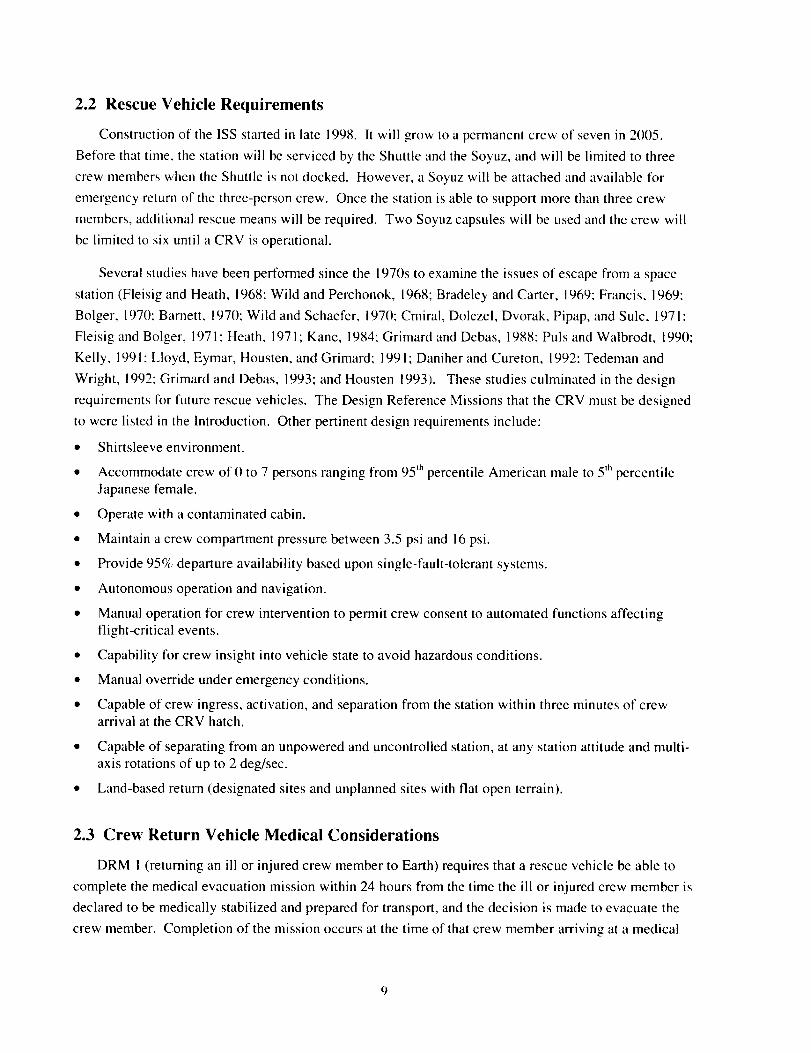
2.3 Crew Return Vehicle Medical Considerations
DRM I (returning an ill or injured crew member to Earth) requires that a rescue vehicle be able to
complete the medical evacuation mission within 24 hours from the time the ill or injured crew member is
declared to be medically stabilized and prepared for transport, and the decision is made to evacuate the
crew member. Completion of the mission occurs at the time of that crew member arriving at a medical
care facility. The mission time from actual separation from the ISS until landing is required to be less
than three hours, and from separation to arrival at a medical care facility is required to be less than six
hours. Additional requirements are that the ill or injured crew member be transported in a recumbent
seat, with required medical equipment accessible to the crew medical officer, who should occupy an
adjacent seat; and that the design should accommodate removal of a passive (unconscious, ill, or injured)
crew member along with their required medical equipment at the landing site. Other medical
requirements are documented in Johnston (1997; personal correspondence, 1998).
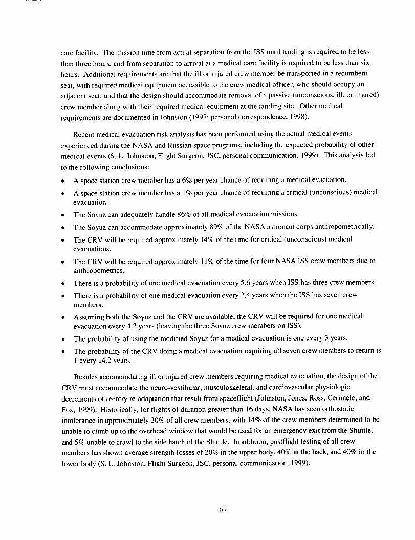
Recent medical evacuation risk analysis has been performed using the actual medical events
experienced during the NASA and Russian space programs, including the expected probability of other
medical events (S. L. Johnston, Flight Surgeon, JSC, personal communication, 1999). This analysis led
to the following conclusions:
* A space station crew member has a 6% per year chance of requiring a medical evacuation.
• A space station crew member has a 1% per year chance of requiring a critical (unconscious) medical
evacuation.
• The Soyuz can adequately handle 86% of all medical evacuation missions.
• The Soyuz can accommodate approximately 89% of the NASA astronaut corps anthropometrically.
• The CRV will be required approximately 14% of the time for critical (unconscious) medicalevacuations.
• The CRV will be required approximately 11% of the time for four NASA ISS crew members due to
anthropometrics.
• There is a probability of one medical evacuation every 5.6 years when ISS has three crew members.
• There is a probability of one medical evacuation every 2.4 years when the ISS has seven crewmembers.
• Assuming both the Soyuz and the CRV are available, the CRV will be required for one medical
evacuation every 4.2 years (leaving the three Soyuz crew members on ISS).
• The probability of using the modified Soyuz for a medical evacuation is one every 3 years.
• The probability of the CRV doing a medical evacuation requiring all seven crew members to return is
1 every 14.2 years.
Besides accommodating ill or injured crew members requiring medical evacuation, the design of the
CRV must accommodate the neuro-vestibular, musculoskeletal, and cardiovascular physiologic
decrements of reentry re-adaptation that result from spaceflight (Johnston, Jones, Ross, Cerimele, and
Fox, 1999). Historically, for flights of duration greater than 16 days, NASA has seen orthostatic
intolerance in approximately 20% of all crew members, with 14% of the crew members determined to be
unable to climb up to the overhead window that would be used for an emergency exit from the Shuttle,
and 5% unable to crawl to the side hatch of the Shuttle. In addition, postflight testing of all crew
members has shown average strength losses of 20% in the upper body, 40% in the back, and 40% in the
lower body (S. L. Johnston, Flight Surgeon, JSC, personal communication, 1999).
10
Further,genderdifferencesmustalsobeaccommodated.Wright-PattersonAFB-sponsoredresearchhasshownapproximately25%lessload-bearingcapabilityin thegeneralpopulationof femalesduetothebearingarea(vertebralsize)andbonedensitydifferencesof gender.Russiantestingof militaryfemalesindicatesa 15%-20c_decrement(J.Brinkley,HumanEffectivenessDirectorate,WrightPattersonAir ForceBase+personalcommunication,1999).
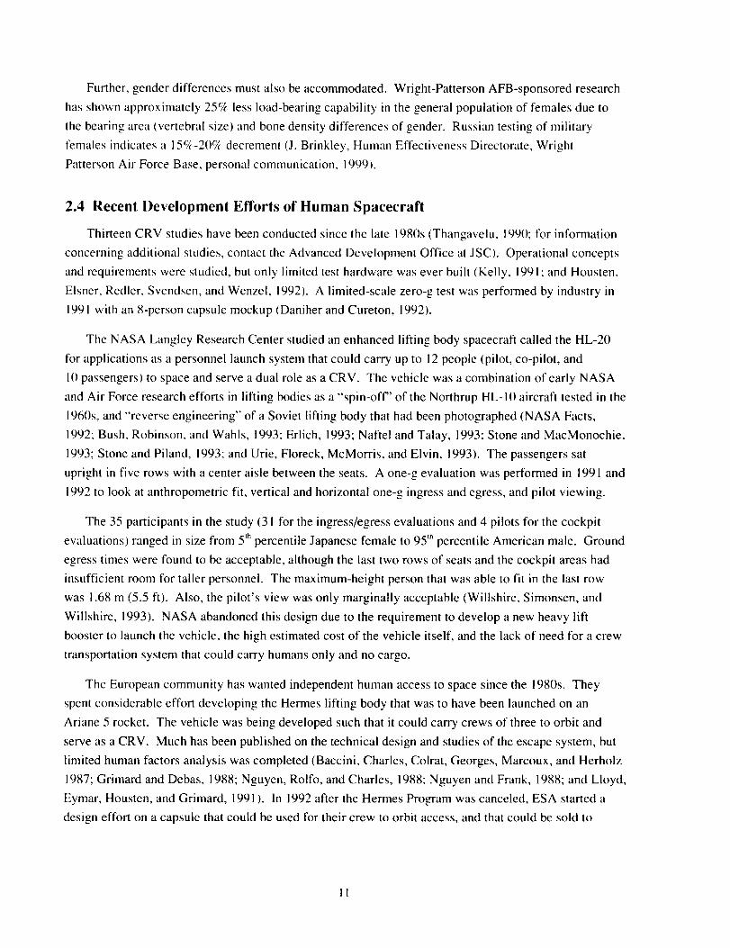
2.4 Recent Development Efforts of Human Spacecraft
Thirteen CRV studies have been conducted since the late 1980s (Thangavelu, 1990; for information
concerning additional studies, contact the Advanced Development Office at JSC). Operational concepts
and requirements were studied, but only limited test hardware was ever built (Kelly, 1991: and Housten,
Elsner, Redler, Svendsen, and Wenzel, 1992). A limited-scale zero-g test was performed by industry in
1991 with an 8-person capsule mockup (Daniher and Cureton, 1992).
The NASA Langley Research Center studied an enhanced lifting body spacecraft called the HL-20
for applications as a personnel launch system that could carry up to 12 people (pilot, co-pilot, and
l0 passengers) to space and serve a dual role as a CRV. The vehicle was a combination of early NASA
and Air Force research efforts in lifting bodies as a "spin-off" of the Northrup HL-10 aircraft tested in the
1960s, and "reverse engineering" of a Soviet lifting body that had been photographed (NASA Facts,
1992: Bush, Robinson, and Wahls, 1993: Erlich, 1993: Naftel and Talay, 1993: Stone and MacMonochie,
1993; Stone and Piland, 1993: and Urie, Floreck, McMorris, and Elvin, 1993). The passengers sat
upright in five rows with a center aisle between the seats. A one-g evaluation was performed in 1991 and
1992 to look at anthropometric fit, vertical and horizontal one-g ingress and egress, and pilot viewing.
The 35 participants in the study (31 for the ingress/egress evaluations and 4 pilots for the cockpit
evaluations) ranged in size from 5 th percentile Japanese female to 95 m percentile American male. Ground
egress times were found to be acceptable, although the last two rows of seats and the cockpit areas had
insufficient room for taller personnel. The maximum-height person that was able to fit in the last row
was 1.68 m (5.5 ft). Also, the pilot's view was only marginally acceptable (Willshire, Simonsen, and
Willshire, 1993). NASA abandoned this design due to the requirement to develop a new heavy lift
booster to launch the vehicle, the high estimated cost of the vehicle itself, and the lack of need for a crew
transportation system that could carry humans only and no cargo.
The European community has wanted independent human access to space since the 1980s. They
spent considerable effort developing the Hermes lifting body that was to have been launched on an
Ariane 5 rocket. The vehicle was being developed such that it could carry crews of three to orbit and
serve as a CRV. Much has been published on the technical design and studies of the escape system, but
limited human factors analysis was completed (Baccini, Charles, Colrat, Georges, Marcoux, and Herholz
1987: Grimard and Debas, 1988; Nguyen, Rolfo, and Charles, 1988; Nguyen and Frank, 1988; and Lloyd,
Eymar, Housten, and Grimard, 1991 ). In 1992 after the Hermes Program was canceled, ESA started a
design effort on a capsule that could be used for their crew to orbit access, and that could be sold to
11

NASA as a CRV (Grimard and Debas, 1993). Subscale flight testing of the capsule continued until ESA
decided to partner with NASA on the X-38 Project (Moskwa, 1996).
Like the Europeans, the Japanese also want independent access to space. They have an active lifting
body/delta wing spacecraft research program under way to develop a spacecraft they call H-II Orbiting
Plane. This vehicle is planned to initially fly without a crew starting well after 2005 to deliver logistics
to the Space Station (Akimoto, Ito, Yamamoto, Bando, and Inoue, 1994; and Shirouzu, Takashi,
Akimoto, Watanabe, and Shimoda, 1994).
The only other human-rated spacecraft flying today is the Soyuz. The Soyuz capsule first flew in
1967 and is still in use by Russia today. In 1992 the U.S. considered buying Soyuz capsules from the
Russians and modifying them to fit the U.S. astronaut population (Housten, 1993). With a habitable
volume of approximately 3 m3 shared by three crew members, the baseline Soyuz descent module has a
very narrow range of crew member heights and weights allowable, as shown in Table 2 contrasted to the
NASA ranges. Approximately 46% of the current U.S. astronaut population will not fit in the standard
Soyuz due to height and weight limitations (Stevenson, 1994). Several anthropometric studies have been
performed on the Soyuz to understand these limitations. Required modifications involve moving the
main instrument panel to accommodate the legs and knees of taller astronauts, seat changes to allow
better muscuioskeletal support of injured crew members, and stowage changes to allow carrying required
medical equipment. Approximately 11% of the U.S. astronaut population will still not fit in a modified
Soyuz. NASA astronauts may fly on the Soyuz and the initial ISS crews must be selected based on who
will fit in the Soyuz.
Table 2. Crew Size and Mass Limits
Soyuz Soyuz NASA NASAMinimum Maximum Minimum Maximum
SeatedHeight 80 (31.5) 96 (37.8) n/a n/acm(in)
UprightHeight 160(63.0) 183(71.7) 148.6(58.5) 193.04(76)cm(in)
Mass 50 (11O) 85 (187) 40(88) 109.32(241)kg (Ib)
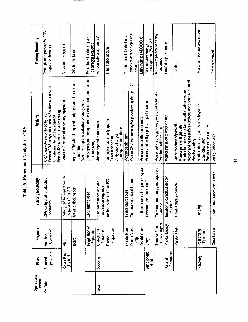
2.5 Crew Events Inside the Crew Return Vehicle
To understand the operational tasks of the crew in a CRV a simplified functional analysis was
performed. The functional analysis allocates functions between humans and machines to: derive crew
mission tasks; identify the information and control inputs required to perform those tasks; determine if
there is adequate time to perform those tasks; ensure that displays and controls support the performance
of those tasks; and specify the criteria to be used in system design (Meister and Rabideau, 1965). This
analysis breaks up the tasks that must be performed into an operational period (e.g. on orbit, or return to
Earth), a phase during that period (e.g. prepare to return, spaceflight, atmospheric flight, landing, etc.), a
segment of the phase (e.g. alerted to problem, board the spacecraft, prepare to separate from the Station,
12
undockandseparatefromtheStation,etc.),thestartingandendingboundariesof the segment in terms of
events, and the activity required during that segment (JSC-28351 : E. Walden, Integradyne, personal
communication, 1998-1999). The results are characterized in Table 3. This research focused on return
preparation through recovery.
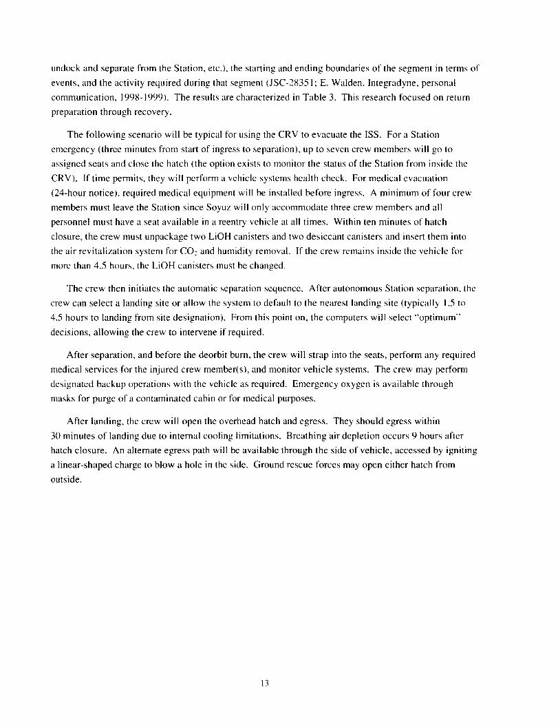
The following scenario will be typical for using the CRV to evacuate the ISS. For a Station
emergency (three minutes from start of ingress to separation), up to seven crew members will go to
assigned seats and close the hatch (the option exists to monitor the status of the Station from inside the
CRV). If time permits, they will perform a vehicle systems health check. For medical evacuation
(24-hour notice), required medical equipment will be installed betore ingress. A minimum of four crew
members must leave the Station since Soyuz will only accommodate three crew members and all
personnel must have a seat available in a reentry vehicle at all times. Within ten minutes of hatch
closure, the crew must unpackage two LiOH canisters and two desiccant canisters and insert them into
the air revitalization system for CO: and humidity removal. If the crew remains inside the vehicle for
more than 4.5 hours, the LiOH canisters must be changed.
The crew then initiates the automatic separation sequence. After autonomous Station separation, the
crew can select a landing site or allow the system to default to the nearest landing site (typically 1.5 to
4.5 hours to landing from site designation). From this point on, the computers will select "'optimum"
decisions, allowing the crew to intervene if required.
After separation, and before the deorbit burn, the crew will strap into the seats, perform any required
medical services for the injured crew member(s), and monitor vehicle systems. The crew may perform
designated backup operations with the vehicle as required. Emergency oxygen is available through
masks for purge of a contaminated cabin or for medical purposes.
After landing, the crew will open the overhead hatch and egress. They should egress within
30 minutes of landing due to internal cooling limitations. Breathing air depletion occurs 9 hours after
hatch closure. An alternate egress path will be available through the side of vehicle, accessed by igniting
a linear-shaped charge to blow a hole in the side. Ground rescue forces may open either hatch from
outside.
13
°l
m
_4
e_
t-
I>
_=0 a_ o -- _ _
w
8_r,z
t_
" _' o E_,=
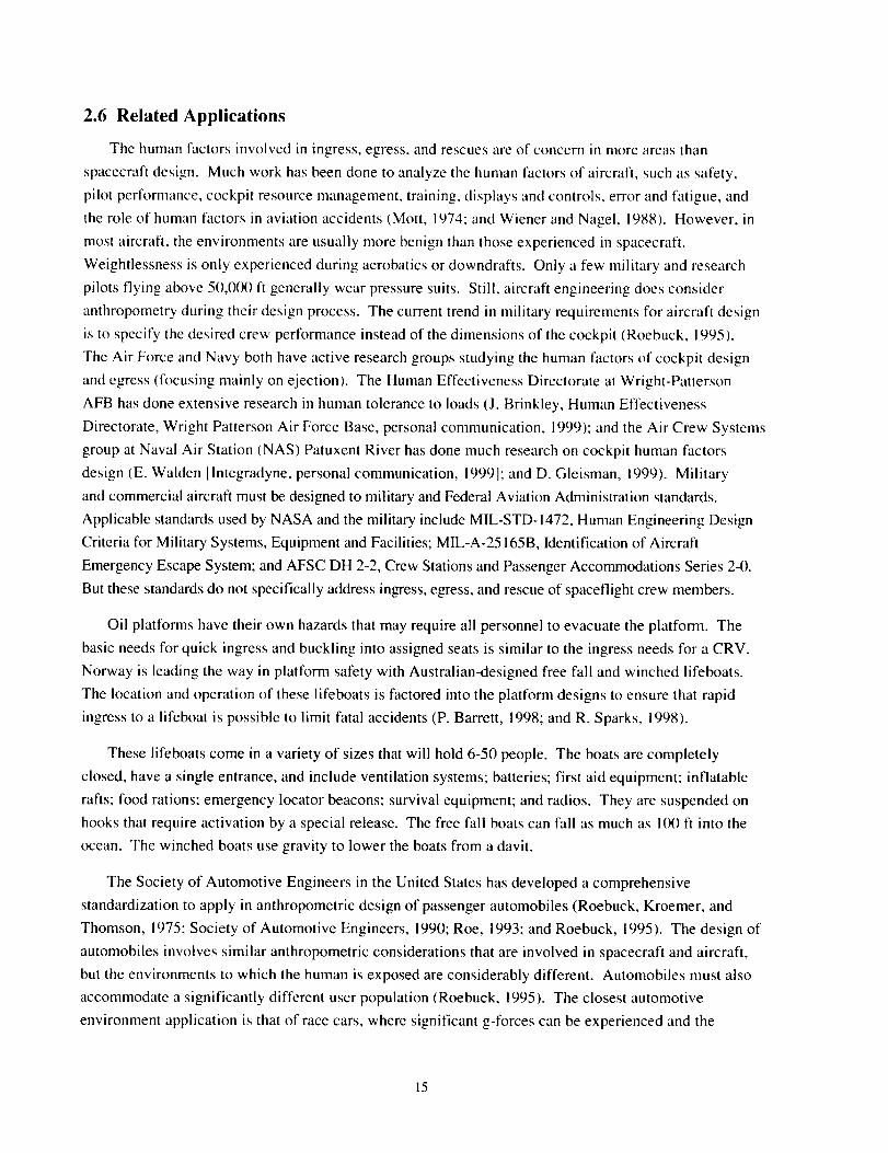
2.6 Related Applications
The human factors involved in ingress, egress, and rescues are of concern in more areas than
spacecraft design. Much work has been done to analyze the human factors of aircraft, such as safety,
pilot performance, cockpit resource management, training, displays and controls, error and fatigue, and
the role of human factors in aviation accidents (Mott, 1974: and Wiener and Nagel, 1988). However, in
most aircraft, the environments are usually more benign than those experienced in spacecraft.
Weightlessness is only experienced during aerobatics or downdrafts. Only a few military and research
pilots flying above 50,000 ft generally wear pressure suits. Still, aircraft engineering does consider
anthropometry during their design process. The current trend in military requirements for aircraft design
is to specify the desired crew performance instead of the dimensions of the cockpit (Roebuck, 1995).
The Air Force and Navy both have active research groups studying the human factors of cockpit design
and egress (focusing mainly on ejection). The Human Effectiveness Directorate at Wright-Patterson
AFB has done extensive research in human tolerance to loads (J. Brinkley, Human Effectiveness
Directorate, Wright Patterson Air Force Base, personal communication, 1999); and the Air Crew Systems
group at Naval Air Station (NAS) Patuxent River has done much research on cockpit human factors
design (E. Walden [Integradyne, personal communication, 1999]: and D. Gleisman, 1999). Military
and commercial aircraft must be designed to military and Federal Aviation Administration standards.
Applicable standards used by NASA and the military include MIL-STD-1472, Human Engineering Design
Criteria for Military Systems, Equipment and Facilities; MIL-A-25165B, Identification of Aircraft
Emergency Escape System; and AFSC DH 2-2, Crew Stations and Passenger Accommodations Series 24).
But these standards do not specifically address ingress, egress, and rescue of spaceflight crew members.
Oil platforms have their own hazards that may require all personnel to evacuate the platform. The
basic needs for quick ingress and buckling into assigned seats is similar to the ingress needs for a CRV.
Norway is leading the way in platform safety with Australian-designed free fall and winched lifeboats.
The location and operation of these lifeboats is factored into the platform designs to ensure that rapid
ingress to a lifeboat is possible to limit fatal accidents (P. Barrett, 1998; and R. Sparks, 1998).
These lifeboats come in a variety of sizes that will hold 6-50 people. The boats are completely
closed, have a single entrance, and include ventilation systems; batteries; first aid equipment; inflatable
rafts: food rations; emergency locator beacons; survival equipment: and radios. They are suspended on
hooks that require activation by a special release. The free fall boats can fall as much as 100 ft into the
ocean. The winched boats use gravity to lower the boats from a davit.
The Society of Automotive Engineers in the United States has developed a comprehensive
standardization to apply in anthropometric design of passenger automobiles (Roebuck, Kroemer, and
Thomson, 1975: Society of Automotive Engineers, 199(I; Roe, 1993; and Roebuck, 1995). The design of
automobiles involves similar anthropometric considerations that are involved in spacecraft and aircraft,
but the environments to which the human is exposed are considerably different. Automobiles must also
accommodate a significantly different user population (Roebuck, 1995). The closest automotive
environment application is that of race cars, where significant g-forces can be experienced and the
15
cockpitsaregenerallymadeassmallaspossibletosaveweightanddrag.Further,the cockpits of race
cars are engineered to provide maximum protection to the driver during high-speed collisions.
2.7 Human Factors Considerations
2.7.1 Use of Mockups
The CRV mockup is a simulation tool that provides the capability for static part-task evaluation of
the ingress and egress mission phases. Mockups provide the opportunity to study the design problem in
three dimensions through both observations and demonstrations. Key uses of mockups include, but are
not limited to (Meister and Rabideau, 1965: and Frisch, 1978):
• Evaluation of alternative equipment configurations.
• Determination of workspace difficulties from simulating operational tasks.
• Identification of accessibility problems from simulating maintenance operations.
• Planning locations for routing wiring, plumbing, etc.
• Determination of geometry or volume problems affecting ingress or egress.
• Evaluation of procedures.
• Determination of optimal placement of crew controls from clearance, reach, and visibility envelopes.
2.7.2 Anthropometry and Human Interfaces
Basic anthropometry and human engineering research, standards, and approaches are well
documented and were utilized throughout this research effort (Roebuck, Kroemer, and Thomson, 1975;
Salvendy, 1992; Woodson, Tiilman, and Tillman, 1992; Roebuck, 1993; and Weimer, 1995). The human
interface requirements of the ISS and the CRV are specified in NASA-STD-3000/T, International Space
Station Flight Crew Integration Standard. The crew module and seats must be designed to accommodate
year 20(X) 40-year-old 95 thpercentile American male and 5 thpercentile Japanese female crew members as
defined by NASA-STD-3000/T, with a 3% spine stretch due to zero gravity. The three dimensions that
must drive the seat design are the sitting height, the popliteal height, and the buttock to popliteal length.
The applicable characteristic human dimensions for a 95 thpercentile American male and 5m percentile
Japanese female in one-g conditions are shown in Table 4, based on a 40-year-old person in year 2000.
Table 5 compares the dimensions for a year 2000 40-year-old 95 thpercentile American male and 5 th
percentile Japanese female at the one-g (no spine stretch) and zero-g conditions (spine stretch and no
buttock pressure), with a 5.08 cm (2 in.) clearance for helmets and a 2.54 cm ( 1 in.) clearance for
dynamic movement of the body due to acceleration forces (NASA-STD-3000/'T; and Peterson, 1996).
Note that 1.3-2 cm (0.5-0.8 in.) is added to the zero-g sitting height due to the relief of pressure on the
buttocks. The final columns with all factors (spine stretch, no buttock pressure, helmet and dynamic
clearance) should be used in seat design. Since the difference in zero-g stature is due to spine stretch,
this difference was added to the one-g sitting height to obtain the zero-g sitting height. The other
dimensions remain unchanged in zero-g.
16
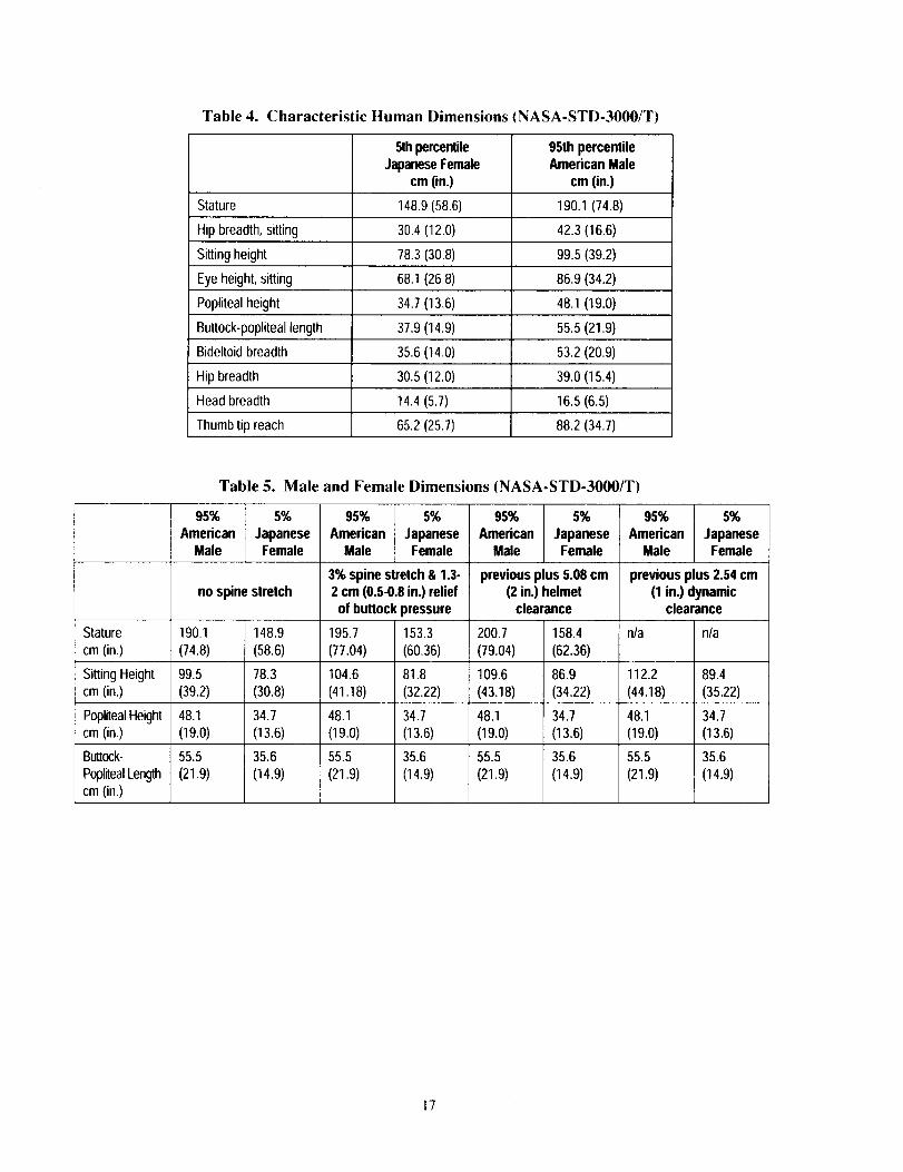
Table 4. Characteristic Human Dimensions (NASA-STD-3000/T)
5th percentile 95th percentile
Japanese Female American Malecm (in.) cm (in.)
Stature 148.9 (58.6) 190.1 (74.8)
Hip breadth, sitting 30.4 (12.0) 42.3 (16.6)
Sitting height 78.3 (30.8) 99.5 (39.2)
Eye height, sitting 68.1 (26.8) 86.9 (34.2)
Popliteal height 34.7 (13.6) 48.1 (19.0)
Buttock-popliteal length 37.9 (14.9) 55.5 (21.9)
Bideltoid breadth 35.6 (14.0) 53.2 (20.9)
Hip breadth 30.5 (12.0) 39.0 (15.4)
Head breadth 14.4 (5.7) 16.5 (6.5)
Thumb tip reach 65.2 (25.7) 88.2 (34.7)
Table 5. Male and Female Dimensions (NASA-STD-3000/T)
95% 5% 95% 5% 95% 5% 95% 5%
American Japanese American Japanese American Japanese American JapaneseMale Female Male Female Male Female Male Female
3% spine stretch & 1.3. previous plus 5.08 cm previous plus 2.54 cm
no spine stretch 2 cm (0.5-0.8 in.) relief (2 in.) helmet (1 in.) dynamicof buttock pressure clearance clearance
Stature 190.1 148.9 195.7 153.3 200.7 158.4 n/a n/a
crn (in.) (74.8) (58.6) (77.04) (60.36) (79.04) (62.36)
Sitting Height 99.5 78.3 104.6 81.8 109.6 86.9 112.2 89.4cm (in.) (39.2) (30.8) (41.18) (32.22) (43.18) (34.22) (44.18) (35.22)
PoplitealHeight 48.1 34.7 48.1 34.7 48.1 34.7 48.1 34.7cm (in.) (19.0) (13.6) (19.0) (13.6) (19.0) (13.6) (19.0) (13.6)
Buttock- 55.5 35.6 55.5 35.6 55.5 35.6 55.5 35.6
PoplitealLength (21.9) (14.9) (21.9) (14.9) (21.9) (14.9) (21.9) (14.9)cm (in.)
17
Chapter 3METHODOLOGY
3.1 Overview
This study was conducted in three parts: ground evaluations, flight evaluations, and a Delphi study.
The evaluations were separated into three phases. Phase 1 was a pilot study using a mockup that seated
four crew members to evaluate the feasibility of the research and establish the initial procedures. Phase 2
was an evaluation with a seven-person mockup to develop the methodology, refine the procedures, and
determine whether any mockup changes were required. Phase 3 was conducted to verify the final
methodology using the same seven-person mockup. Data analysis was performed for Phase 3. The
Delphi study was conducted between Phases 2 and 3 to determine the evaluation factors that the end
users (astronauts and flight surgeons) deemed most important.
The human factors evaluations included human test participants in all phases of ground and inflight
tests. The inflight tests were performed in the NASA KC-135 zero-g aircraft using the methodology
developed. Further, specific design issues addressed in the evaluations included:
• Preferred hatch stowage locations.
• Suitability and function of conceptual layout (seats, stowage, displays, handholds, etc.).
• Ease of ingress for deconditioned and injured persons.
• Assessment of optimal seat locations for crew control and ill or injured crew.
• Assessment of general crew module volume.
A full-scale crew module mockup of the X-38 was built and outfitted with the proposed seat
configuration, medical equipment mockups and high-fidelity training hardware, low-fidelity crew
displays and controls mockups, low fidelity hatch, and volumetric mockups of spacecraft systems and
stowed equipment. The evaluations were performed on a single seat layout.
Ground and flight evaluations encompassed the performance of expected crew member operations,
including zero-g ingress and egress, specified medical care, hatch opening and closing, seat comfort, seat
adjustments, handhold utility, reach and visibility of displays and controls, and accessing storage areas.
While representative systems displays were available in Phase 2 as part of a secondary study, this
research only considered the spatial and physiological aspects of display location and not the cognitive
use of the displays.
Each series of evaluations began with one-g ground tests to evaluate the reach, visibility, operability,
functionality, and suitability of the layout. The ground evaluation was used to evaluate the mockup and
equipment layouts before flight test in order to identify any potential problems or interferences, and to
dry run the inflight evaluation procedures. The participants were asked about comfort throughout the
adjustment range of the seats on the ground. Pertinent comments and observations were incorporated
into hardware and procedures for the flight tests on the NASA zero-g aircraft.
18
The flight evaluations were conducted under three acceleration environments: zero g, one g, and 1.8
g's. The flight test series for Phase 1 was conducted during four parabolic flights of 40 parabolas each,
for a total of 160 parabolas. The Phase 2 evaluations were perlormed during three separate parabolic
zero-g flights, with 46, 53, and 40 parabolas each, for a total of 139 parabolas. Phase 3 flight
evaluations were conducted during two flights of 48 and 46 parabolas, for a total of 94 parabolas. The
test objectives of the ground and flight evaluations are detailed in the procedures section. The three
acceleration test environments allowed adequate evaluation of the crew module volume, layout, and
functionality in the expected operating environment. The 1.8-g environment was used to approximate the
higher-g's of spacecraft reentry, and was used to grossly simulate a deconditioned crew member's
reflexes.
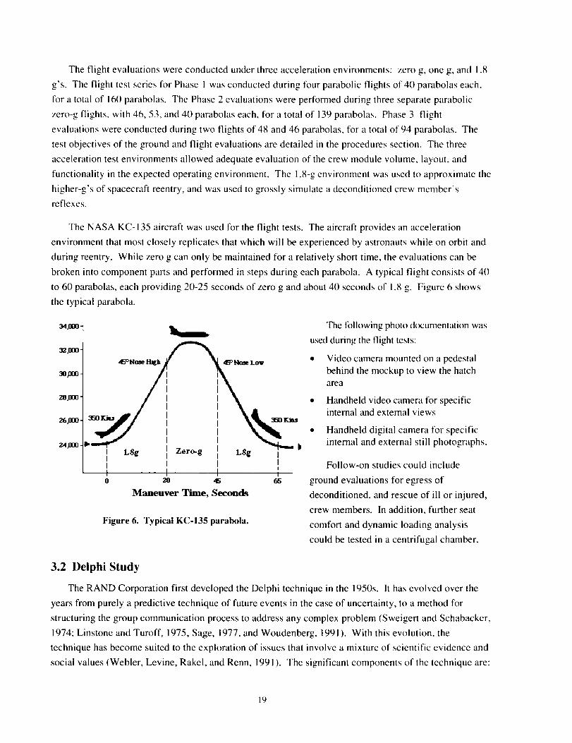
The NASA KC-135 aircraft was used for the flight tests. The aircraft provides an acceleration
environment that most closely replicates that which will be experienced by astronauts while on orbit and
during reentry. While zero g can only be maintained for a relatively short time, the evaluations can be
broken into component parts and performed in steps during each parabola. A typical flight consists of 40
to 60 parabolas, each providing 20-25 seconds of zero g and about 40 seconds of 1.8 g. Figure 6 shows
the typical parabola.
349oo-
i
_,0oo-
7_.4,ooo.
45°H__ Low
I L$g Zero-g LSg III II iI0 20 45 65
Maneuver Time, Seconds
Figure 6. Typical KC-135 parabola.
The following photo documentation was
used during the flight tests:
• Video camera mounted on a pedestal
behind the mockup to view the hatch
area
• Handheld video camera for specificinternal and external views
• Handheld digital camera for specific
internal and external still photographs.
Follow-on studies could include
ground evaluations for egress of
deconditioned, and rescue of ill or injured,
crew members. In addition, further seat
comfort and dynamic loading analysis
could be tested in a centrifugal chamber.
3.2 Delphi Study
The RAND Corporation first developed the Delphi technique in the 1950s. It has evolved over the
years from purely a predictive technique of future events in the case of uncertainty, to a method for
structuring the group communication process to address any complex problem (Sweigert and Schabacker,
1974; Linstone and Turoff, 1975, Sage, 1977, and Woudenberg, 1991 ). With this evolution, the
technique has become suited to the exploration of issues that involve a mixture of scientific evidence and
social values (Webler, Levine, Rakel, and Renn, 1991). The significant components of the technique are:
19
• Feedback of individual contributions of information and knowledge.
• Assessment of group judgment or view.
• Opportunity for individual contributors to respond to and revise their views until a consensus is reached.
A modified Delphi study was performed to elicit and refine the opinions of the user groups of human
spacecraft on the variables and factors that should be considered in an evaluation methodology. This
study used the collective judgment of experts to derive a consensus position (Dalkey, 1967, Helmer,
1983, and Johnson and King, 1988).
The Delphi study used in this research began by working with a member of the astronaut corps to
develop the basic list of factors to be considered. A questionnaire was developed that asked the
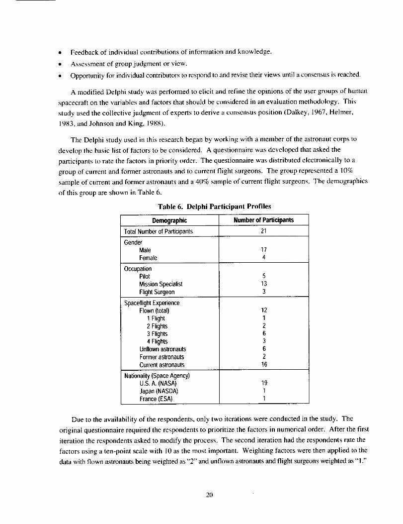
participants to rate the factors in priority order. The questionnaire was distributed electronically to a
group of current and former astronauts and to current flight surgeons. The group represented a 10%
sample of current and former astronauts and a 40% sample of current flight surgeons. The demographics
of this group are shown in Table 6.
Table 6. Delphi Participant Profiles
Demographic Number of Participants
Total Numberof Participants 21
GenderMale 17
Female 4
OccupationPilot 5
Mission Specialist 13
Flight Surgeon 3
Spaceflight ExperienceFlown (total)
1 Flight
2 Flights
3 Flights4 Flights
Unflown astronauts
Former astronauts
Current astronauts
Nationality(Space Agency)U.S.A.(NASA)
Japan(NASDA)
France(ESA)
12
12
63
6
2
16
19
11
Due to the availability of the respondents, only two iterations were conducted in the study. The
original questionnaire required the respondents to prioritize the factors in numerical order. After the first
iteration the respondents asked to modify the process. The second iteration had the respondents rate the
factors using a ten-point scale with 10 as the most important. Weighting factors were then applied to the
data with flown astronauts being weighted as "2" and unflown astronauts and flight surgeons weighted as "1."
20
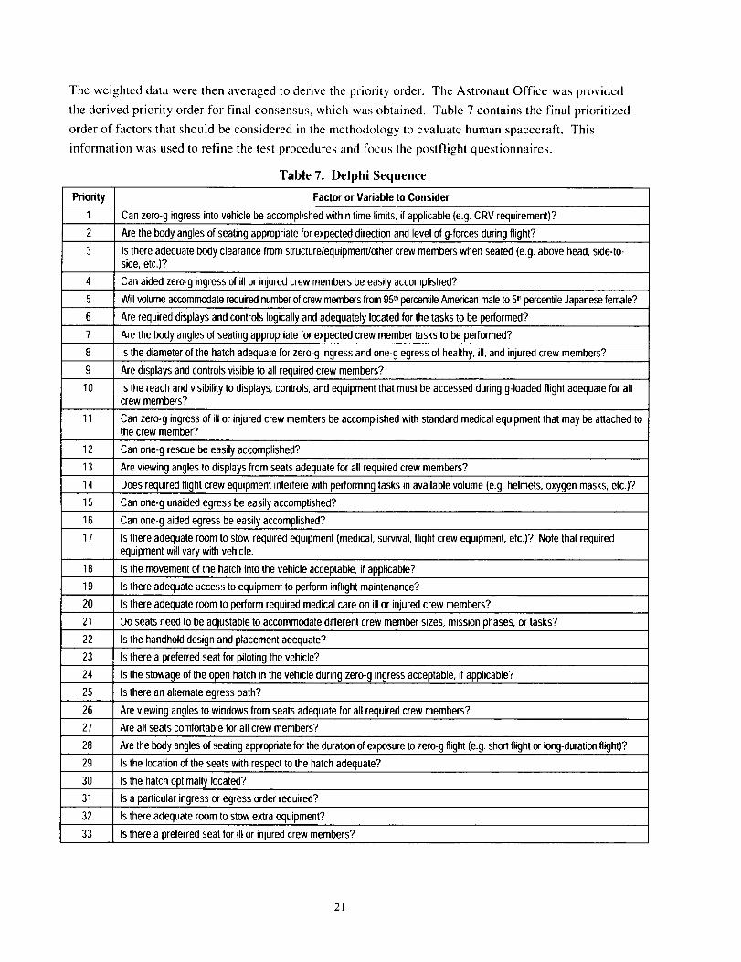
Theweighteddatawerethenaveragedtoderivethepriorityorder.TheAstronautOfficewasprovidedthederivedpriorityorderfor finalconsensus,whichwasobtained.Table7containsthefinalprioritizedorderof factorsthatshouldbeconsideredin themethodologytoevaluatehumanspacecraft.Thisinformationwasusedto refinethetestproceduresandfocusthepostflightquestionnaires.
Table7. Delphi Sequence
Priority Factoror Variableto Consider
1 Can zero-g ingressintovehiclebeaccomplishedwithintime limits, if applicable (e.g.CRV requirement)?
2 Arethebody anglesof seating appropriate for expecteddirection and level of g-forcesduring flight?
3 Is there adequatebody clearance from structure/equipmentJothercrew memberswhen seated(e.g. above head,side-to-side,etc.)?
4 Can aided zero-g ingress of ill or injured crewmembers beeasily accomplished?
5 Will volumeaccommodaterequirednumberof crewmembersfrom95thpercentileAmericanmaleto 5= percentileJapanesefemale?
6 Are requireddisplaysand controls logically andadequately located for the tasks to be performed?
7 Are the body angles of seating appropriatefor expectedcrew member tasks to be performed?
8 Isthe diameterof the hatch adequate for zero-g ingress and one-g egressof healthy, ill, and injured crewmembers?
9 Are displays andcontrolsvisible to all requiredcrew members?
10 Isthe reach andvisibility to displays, controls,and equipment that must be accessed duringg-loaded flight adequatefor allcrew members?
11 Can zero-g ingress of ill or injuredcrew membersbe accomplishedwith standard medicalequipment that may beattached tothe crew member?
12 Can one-g rescuebeeasily accomplished?
13 Are viewing angles todisplays from seatsadequatefor all required crewmembers?
14 Does required flight crew equipment interferewith performingtasks in available volume (e.g. helmets, oxygen masks, etc.)?
15 Can one-g unaidedegressbe easily accomplished?
16 Can one-g aided egress beeasily accomplished?
17 Is there adequateroom to stow required equipment(medical, survival,flight crew equipment,etc.)? Note that requiredequipmentwilt varywith vehicle.
18 Is the movementof the hatch into thevehicle acceptable, if applicable?
19 Is there adequateaccess to equipmentto perform inflight maintenance?
20 Is there adequateroom to perform requiredmedical care on ill or injuredcrew members?
21 Do seats need to be adjustable to accommodatedifferent crew member sizes, mission phases,or tasks?
22 Is thehandholddesign and placementadequate?
23 Is there a preferred seat for piloting thevehicle?
24 Is thestowageof the open hatch in the vehicleduring zero-g ingress acceptable, if applicable?
25 Is therean alternateegress path?
26 Are viewing anglesto windows from seats adequatefor all requiredcrew members?
27 Are all seatscomfortable for all crew members?
28 Are the bodyanglesof seating appropriatefor thedurationof exposureto zero-gflight (e.g.shortflight or long-durationfligh0?
29 Is the locationof the seats withrespectto the hatch adequate?
30 Is the hatch optimallylocated?
3t Is a particular ingress or egress order required?
32 Isthere adequate room to stow extra equipment?
33 Isthere a preferred seat for ill or injuredcrew members?
21
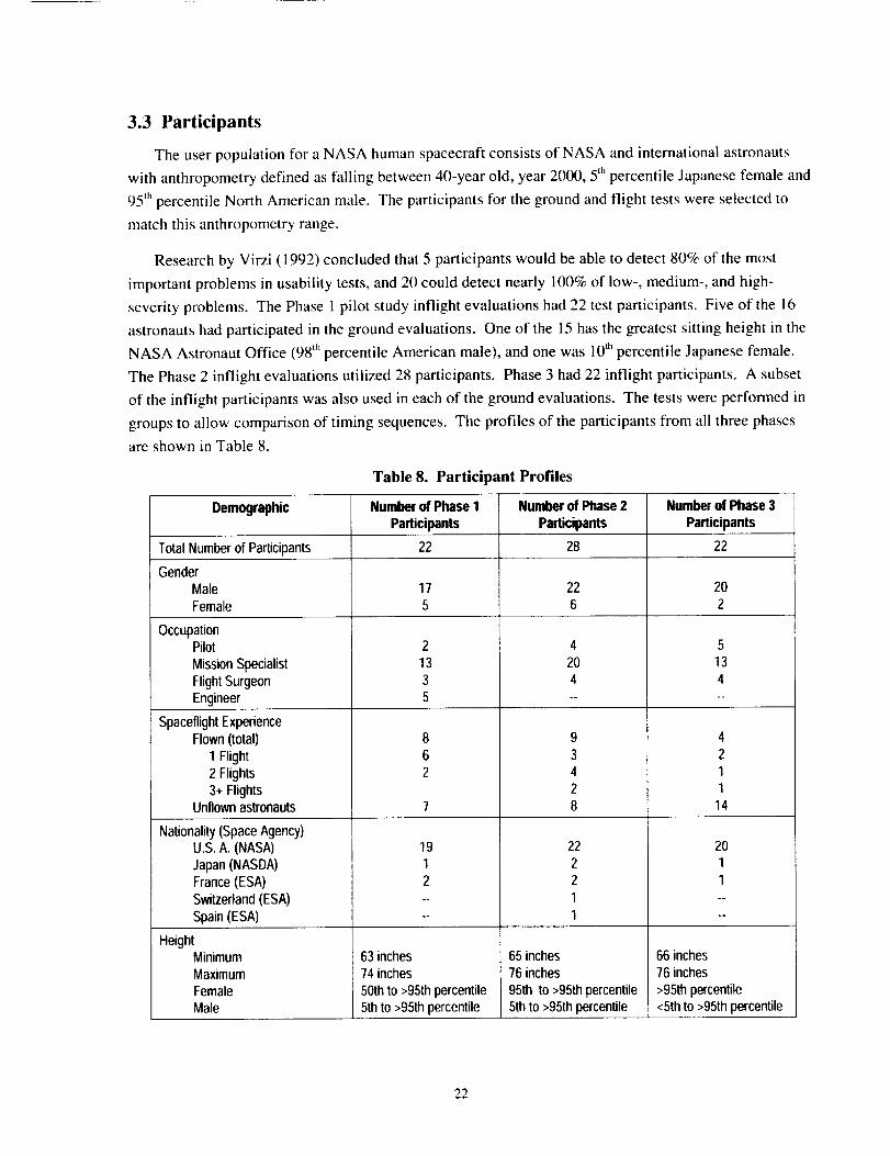
3.3 Participants
The user population for a NASA human spacecraft consists of NASA and international astronauts
with anthropometry defined as falling between 40-year old, year 2(100, 5" percentile Japanese female and
95 th percentile North American male. The participants for the ground and flight tests were selected to
match this anthropometry range.
Research by Virzi (1992) concluded that 5 participants would be able to detect 80% of the most
important problems in usability tests, and 20 could detect nearly 100% of low-, medium-, and high-
severity problems. The Phase 1 pilot study inflight evaluations had 22 test participants. Five of the 16
astronauts had participated in the ground evaluations. One of the 15 has the greatest sitting height in the
NASA Astronaut Office (98 th percentile American male), and one was 10 th percentile Japanese female.
The Phase 2 inflight evaluations utilized 28 participants. Phase 3 had 22 inflight participants. A subset
of the inflight participants was also used in each of the ground evaluations. The tests were performed in
groups to allow comparison of timing sequences. The profiles of the participants from all three phases
are shown in Table 8.
Table 8. Participant Profiles
Demographic Number of Phase I Number of Phase 2 Number of Phase 3Participants Participants Participants
Total Number of Participants 22 28 22
Gender
Male 17 22 20Female 5 6 2
OccupationPilot
Mission Specialist
Flight SurgeonEngineer
SpaceflightExperience
Flown (total)
1 Flight
2 Flights3+ Flights
Unflown astronauts
Nationality(Space Agency)U.S.A.(NASA)
Japan(NASDA)
France(ESA)
Switzerland(ESA)
Spain(ESA)
HeightMinimum
MaximumFemale
Male
13
3
5
19
1
2
20
4
93
4
28
22
2
21
1
63inches74inches
65inches
76inches
66inches
76inches
50th to >95th percentile
5th to >95th percentile
95th to >95th percentile5th to >95th percentile
5
13
4
4
2
11
14
201
1..
..
>95th percentile<5th to >95th percentile
22
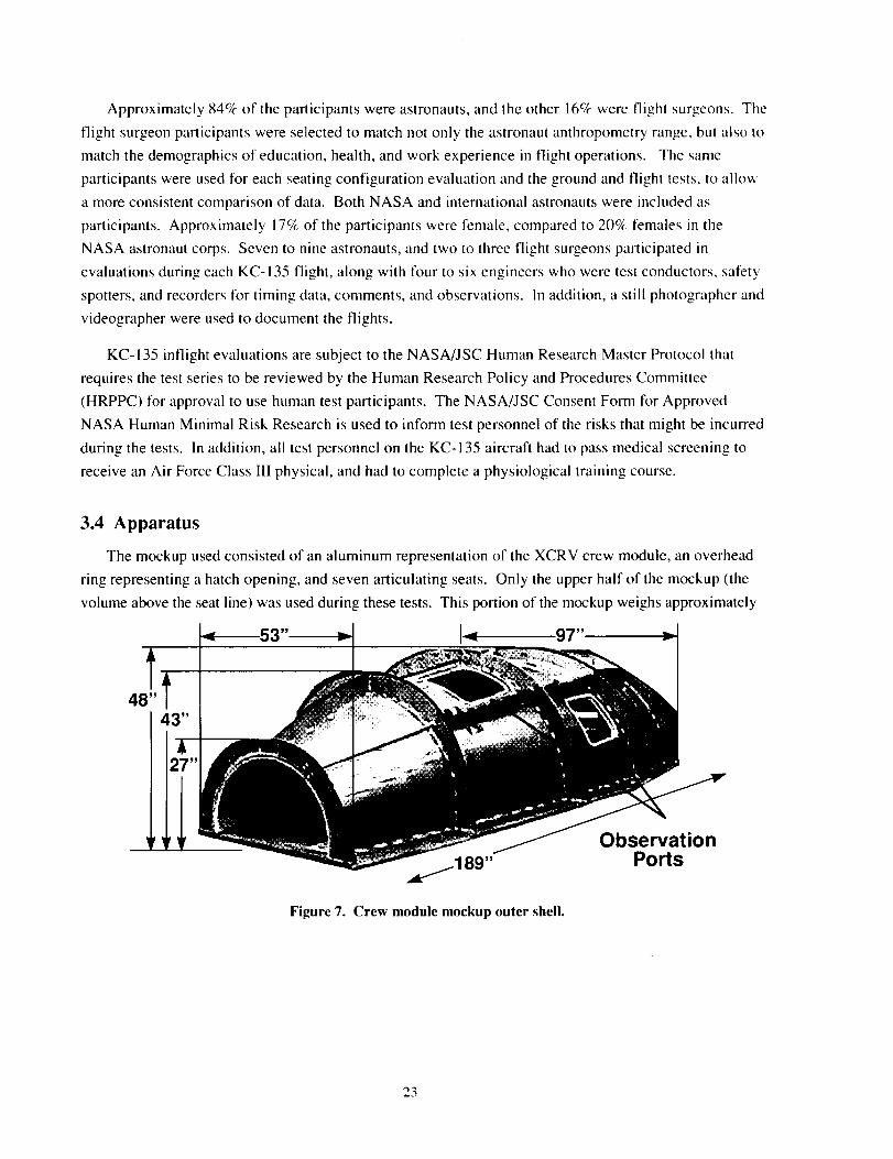
Approximately 84% of the participants were astronauts, and the other 16% were flight surgeons. The
flight surgeon participants were selected to match not only the astronaut anthropometry range, but also to
match the demographics of education, health, and work experience in flight operations. The same
participants were used for each seating configuration evaluation and the ground and flight tests, to allow
a more consistent comparison of data. Both NASA and international astronauts were included as
participants. Approximately 17% of the participants were female, compared to 20% females in the
NASA astronaut corps. Seven to nine astronauts, and two to three flight surgeons participated in
evaluations during each KC-135 flight, along with four to six engineers who were test conductors, safety
spotters, and recorders for timing data, comments, and observations. In addition, a still photographer and
videographer were used to document the flights.
KC-135 inflight evaluations are subject to the NASA/JSC Human Research Master Protocol that
requires the test series to be reviewed by the Human Research Policy and Procedures Committee
(HRPPC) for approval to use human test participants. The NASA/JSC Consent Form for Approved
NASA Human Minimal Risk Research is used to inform test personnel of the risks that might be incurred
during the tests. In addition, all test personnel on the KC-135 aircraft had to pass medical screening to
receive an Air Force Class IlI physical, and had to complete a physiological training course.
3.4 Apparatus
The mockup used consisted of an aluminum representation of the XCRV crew module, an overhead
ring representing a hatch opening, and seven articulating seats. Only the upper half of the mockup (the
volume above the seat line) was used during these tests. This portion of the mockup weighs approximately
53 14 97"
Figure 7. Crew module mockup outer shell.
ObservationPorts
23
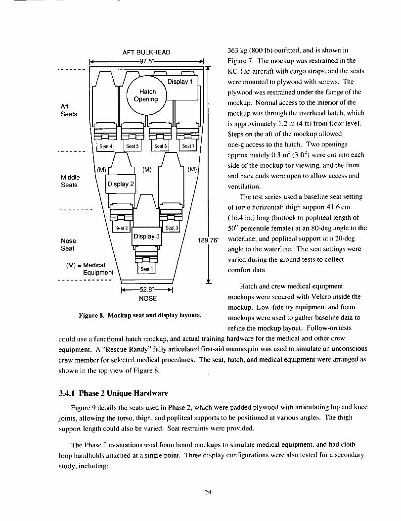
AFTBULKHEAD_" 97.5"I TM
AftSeats
MiddleSeats
Nose 189.76"
Seat 1(M) = Medical
Equipment
J_-----52.8"_NOSE
Figure 8. Mockup seat and display layouts.
could use a functional hatch mockup, and actual training
363 kg (800 lb) outfitted, and is shown in
Figure 7. The mockup was restrained in the
KC- 135 aircraft with cargo straps, and the seats
were mounted to plywood with screws. The
plywood was restrained under the flange of the
mockup. Normal access to the interior of the
mockup was through the overhead hatch, which
is approximately 1.2 m (4 ft) from floor level.
Steps on the aft of the mockup allowed
one-g access to the hatch. Two openings
approximately 0.3 m2 (3 ft 2) were cut into each
side of the mockup for viewing, and the front
and back ends were open to allow access and
ventilation.
The test series used a baseline seat setting
of torso horizontal; thigh support 41.6 cm
(16.4 in.) long (buttock to poplitea! length of
50 thpercentile female) at an 80-deg angle to the
waterline: and popliteal support at a 20-deg
angle to the waterline. The seat settings were
varied during the ground tests to collect
comfort data.
Hatch and crew medical equipment
mockups were secured with Velcro inside the
mockup. Lo_-fidelity equipment and foam
mockups were used to gather baseline data to
refine the mockup layout. Follow-on tests
hardware for the medical and other crew
equipment. A "Rescue Randy" fully articulated first-aid mannequin was used to simulate an unconscious
crew member for selected medical procedures. The seat, hatch, and medical equipment were arranged as
shown in the top view of Figure 8.
3.4.1 Phase 2 Unique Hardware
Figure 9 details the seats used in Phase 2, which were padded plywood with articulating hip and knee
joints, allowing the torso, thigh, and popliteal supports to be positioned at various angles. The thigh
support length could also be varied. Seat restraints were provided.
The Phase 2 evaluations used foam board mockups to simulate medical equipment, and had cloth
loop handholds attached at a single point. Three display configurations were also tested for a secondary
study, including:
24
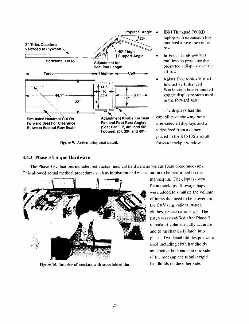
2" Thick CushionsVelcroed to Plywood \
Horizontal Torso
-¢ Torso
......... I
"\ "\Simulated Headrest Cut OnForward Seat For ClearanceBetween Second Row Seats
22"
Popliteal Angle
Adjustment forSeat Pan Length
Thigh--_ ._l------Calf------_
_1_14"5''to
22.6"18"+
I
14"
+n
Adjustment Knobs For SeatPan and Foot Rest Angles(Seat Pan 300, 400, and 500,Footrest20°, 300, and 400)
Figure 9. Articulating seat detail.
• IBM Thinkpad 760XD
laptop with expansion traymounted above the center
row.
• In-Focus LitePro® 720
multimedia projector that
projected a display over theaft row.
• Kaiser Electronics VirtualInteractive Enhanced
Workstation head-mounted
goggle display system usedin the forward seat.
The displays had the
capability of showing both
user-selected displays and a
video feed from a camera
placed in the KC-135 aircraft
forward cockpit window.
3.4.2 Phase 3 Unique Hardware
The Phase 3 evaluations included both actual medical hardware as well as foam board mockups.
This allowed actual medical procedures such as intubation and resuscitation to be performed on the
Figure 10. Interior of mockup with seats folded flat.
mannequin. The displays were
foam mockups. Stowage bags
were added to simulate the volume
of items that need to be stowed on
the CRV (e.g. rations, water,
clothes, rescue radio, etc.). The
hatch was modified after Phase 2
to make it volumetrically accurate
and to mechanically latch into
place. Two handhold designs were
used including cloth handholds
attached at both ends on one side
of the mockup and tubular rigid
handholds on the other side.
25
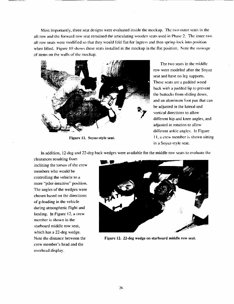
Mostimportantly,threeseatdesignswereevaluatedinsidethemockup.Thetwoouterseatsin theaft rowandtheforwardrowseatremainedthearticulatingwoodenseatsusedinPhase2. Theinnertwoaft rowseatsweremodifiedsothattheywouldfoldflat for ingressandthenspring-lockintopositionwhenlifted. Figurel0 showstheseseatsinstalledin themockupin theflatposition.Notethestowageof itemsonthewallsof themockup.
Thetwoseatsin themiddlerowweremodeledaftertheSoyuzseatandhaveno legsupports.
_ Theseseatsareapaddedwoodbackwithapaddedlip to preventthebuttocksfromslidingdown,
........andanaluminumfootpanthatcani i i ii_ii!
be adjusted in the lateral and
vertical directions to allow
different hip and knee angles, and
adjusted in rotation to allow
different ankle angles. In Figure
Figure 11. Soyuz-style seat. 11, a crew member is shown sitting
in a Soyuz-style seat.
In addition, 12-deg and 22-deg back wedges were available for the middle row seats to evaluate the
clearances resulting from
inclining the torsos of the crew
members who would be
controlling the vehicle to a
more "pilot-intuitive" position.
The angles of the wedges were
chosen based on the directions
of g-loading in the vehicle
during atmospheric flight and
landing. In Figure 12, a crew
member is shown in the
starboard middle row seat,
which has a 22-deg wedge.
Note the distance between the
crew member's head and the
overhead display.
Figure 12. 22-deg wedge on starboard middle row seat.
26
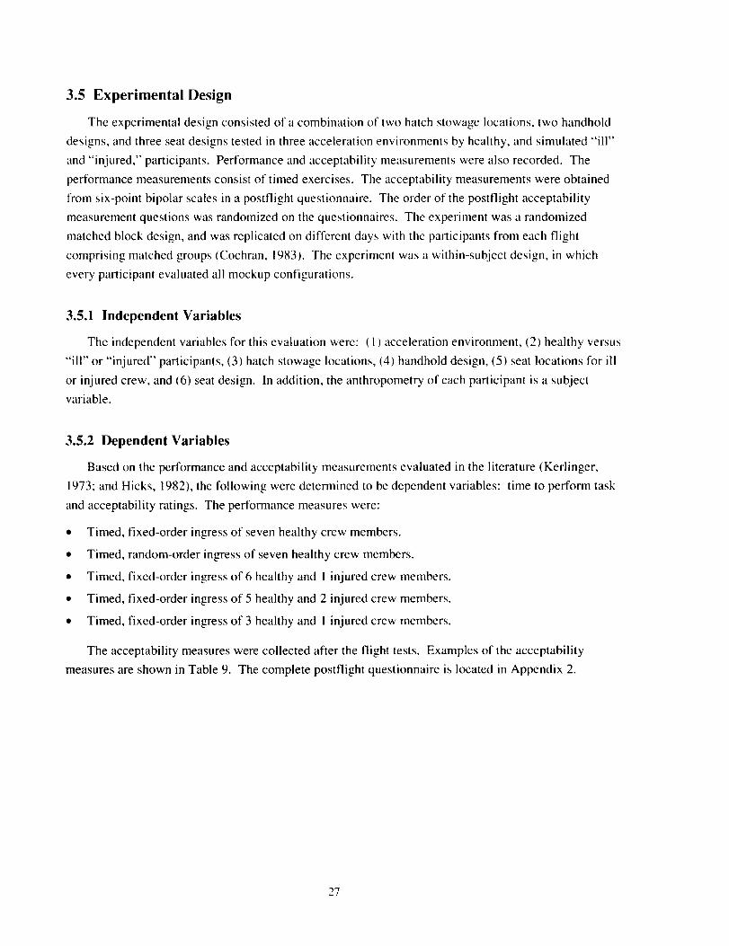
3.5 Experimental Design
The experimental design consisted of a combination of two hatch stowage locations, two handhold
designs, and three seat designs tested in three acceleration environments by healthy, and simulated "ill"
and "injured," participants. Performance and acceptability measurements were also recorded. The
performance measurements consist of timed exercises. The acceptability measurements were obtained
from six-point bipolar scales in a postflight questionnaire. The order of the postflight acceptability
measurement questions was randomized on the questionnaires. The experiment was a randomized
matched block design, and was replicated on different days with the participants from each flight
comprising matched groups (Cochran, 1983). The experiment was a within-subject design, in which
every participant evaluated all mockup configurations.
3.5.1 Independent Variables
The independent variables for this evaluation were: ( 1) acceleration environment, (2) healthy versus
"ill" or "injured" participants, (3) hatch stowage locations, (4) handhold design, (5) seat locations for ill
or injured crew, and (6) seat design. In addition, the anthropometry of each participant is a subject
variable.
3.5.2 Dependent Variables
Based on the performance and acceptability measurements evaluated in the literature (Kerlinger,
1973; and Hicks, 1982), the following were determined to be dependent variables: time to perform task
and acceptability ratings. The performance measures were:
• Timed, fixed-order ingress of seven healthy crew members.
• Timed, random-order ingress of seven healthy crew members.
• Timed, fixed-order ingress of 6 healthy and I injured crew members.
• Timed, fixed-order ingress of 5 healthy and 2 injured crew members.
• Timed, fixed-order ingress of 3 healthy and I injured crew members.
The acceptability measures were collected after the flight tests. Examples of the acceptability
measures are shown in Table 9. The complete postflight questionnaire is located in Appendix 2.
27
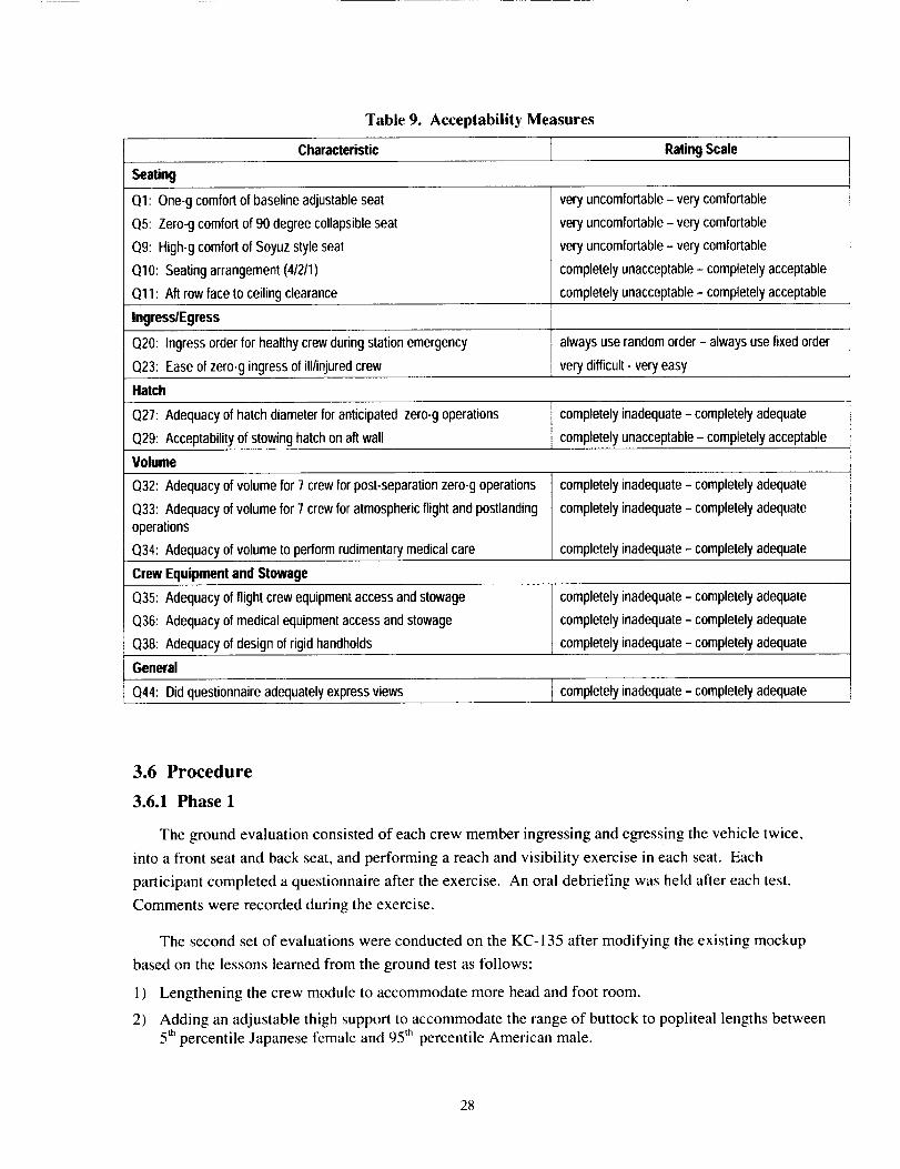
Table 9. Acceptability Measures
Characteristic RatingScale
Seating
Ol: One-gcomfortof baselineadjustableseat
O5: Zero-gcomfortof 90degreecollapsibleseat
09: High-gcomfortof Soyuzstyleseat
OlO: Seatingarrangement(41211)
011: Aft row faceto ceilingclearance
veryuncomfortable- verycomfortable
veryuncomfortable- verycomfortable
veryuncomfortable- verycomfortable
completelyunacceptable- completelyacceptable
completelyunacceptable- completelyacceptable
Ingress/Egress
O20: Ingressorder for healthycrewduringstationemergency alwaysuse randomorder- alwaysusefixedorder
Q23: Easeof zero-gingressof ill/injuredcrew verydifficult- veryeasy
Hatch
Q27: Adequacyof hatchdiameterforanticipated zero-goperations completelyinadequate- completelyadequate
Q29: Acceptabilityof stowinghatchonaft wall completelyunacceptable- completelyacceptable
Volume
Q32: Adequacyof volumefor 7 crewfor post-separationzero-goperations
Q33: Adequacyof volumefor 7crewfor atmosphericflightand postlandingoperations
Q34: Adequacyof volumeto performrudimentarymedicalcare
completelyinadequate- completelyadequate
completelyinadequate- completelyadequate
completelyinadequate- completelyadequate
CrewEquipmentandStowage
Q35: Adequacyofflightcrewequipmentaccessandstowage
Q36: Adequacyof medicalequipmentaccessandstowage
Q38: Adequacyof designof rigidhandholds
General
Q44: Did questionnaireadequatelyexpressviews
completelyinadequate- completelyadequate
completelyinadequate- completelyadequate
completelyinadequate- completelyadequate
completelyinadequate- completelyadequate
3.6 Procedure
3.6.1 Phase 1
The ground evaluation consisted of each crew member ingressing and egressing the vehicle twice,
into a front seat and back seat, and performing a reach and visibility exercise in each seat. Each
participant completed a questionnaire after the exercise. An oral debriefing was held after each test.
Comments were recorded during the exercise.
The second set of evaluations were conducted on the KC-135 after modifying the existing mockup
based on the lessons learned from the ground test as follows:
1) Lengthening the crew module to accommodate more head and foot room.
2) Adding an adjustable thigh support to accommodate the range of buttock to popliteal lengths between
5 thpercentile Japanese female and 95 th percentile American male.
28
3) Changingthekneeangleto20deg(waszero)toaccommodatestowageofequipmentbelowtheseats.
4) Relocatingthehatchtooverthebackrowof seats.
5) Addingextrahandholds.
Flightevaluationsincludedtimedzero-gingressandegress(healthyandunconscious),hatchoperations,LiOHcanisteroperations,medicaltreatment,reachandvisibility,handholdplacement,equipmentlocation,seatdesign,buttockto popliteallengthevaluations,1.8-gcomfort,andsuitabilityofthreedifferenthelmetdesigns.Writtencrewcomments,dynamicanthropometricmeasurements,andingressandegresstimingdatawerealsocollected.
3.6.2 Phases 2 and 3
One seat layout capable of accommodating multiple seat designs and seat angle configurations was
evaluated in Phases 2 and 3. Evaluations were performed in three different acceleration environments
using astronauts and flight surgeon test participants. All evaluations were performed using the full-scale
crew module mockup with representative equipment mockups inside. The flight test had a formal test
plan, procedures, and post-test questionnaire for data collection. The test plan followed the guidelines
established by the JSC Flight Crew Operations Directorate. The one-g dry rtm test also used the flight
test procedures.
A summary of the test and copies of the procedures were made available to test participants before
the test. All participants in each evaluation attended a pre-test briefing, at which the test objectives were
explained and a familiarization of the mockup including hatch and seat function was conducted. They
also participated in a post-test debriefing where their comments were collected. Data collection included
recorded times for specific events; recorded measurements of specified anthropometric data in each seat
design; pertinent observations, in-test comments, and debriefing comments recorded by test conductors:
post-test questionnaires completed by test participants; still photographs of tests; video of tests: and
anthropometric data of astronaut test participants.
The participants conducted the evaluations by climbing into the mockup and performing one-g
volumetric and operational assessments, and then performing egresses. The specific test objectives of the
one-g tests included evaluations of:
• Evaluation of seat dimensions and seat comfort (torso, thigh, and popliteal lengths, hip flexion andknee flexion angles, and torso angles).
• Evaluation of hatch stowage on aft wall and overhead.
• Assessment of ease of medical care in crew module.
The participants conducted the evaluations by performing timed zero-g ingresses and hatch closure,
zero-g and 1.8-g volumetric and operational evaluations inside the crew module, and zero-g timed hatch
opening and egresses. An orientation parabola was used at the start of each flight to allow the evaluators
to familiarize themselves with the physiological aspects of parabolic flight (steep pullup, followed by
weightlessness, followed by 1.8-g pullout dive). The evaluators then conducted a practice zero-g ingress
29
andegressto familiarizethemselveswiththetasks.Thespecifictestof objectives of the zero-g flights
included evaluations of:
• Timed zero-g entry through the hatch to and from each seat (aided and unaided).
• Evaluation of hatch stowage on aft wall and overhead.
• Evaluation of handhold design, placement, and number.
• Evaluation of seat layout.
• Assessment of seat designs.
• general available volume for seven crew members.
• optimal seat(s) for crew member responsible for interfacing with computers and/or
Assessment of
Assessment of
crew displays.
Assessment of
Assessment of
Assessment of
Assessment of
• optimal seat(s) for ill or injured crew members.
• general access, reach, and visibility of medical equipment.
• equipment stowage locations.
• ease of medical care during g-loaded and zero-g flight.
The test plans and documentation required to perform the Phase 2 and Phase 3 test series were
completed (Sanchez, 1998a; Sanchez, 1998b; Manley, 1998a; Manley, 1998b; Sanchez, 1999a; Sanchez,
1999b). The procedure for the Phase 3 flight test series is attached as Appendix I, and the postflight
questionnaire for Phase 3 is attached as Appendix 2.
NASA, Boeing North America, and Alenia Aerospazio jointly conducted parts of Phase 2. The
NASA portion included only CRV evaluations while the Boeing portion included a reduced-volume CRV
evaluation and joint CTV evaluations with Alenia as part of an industry evaluation of the XCRV design
(Manley, Basile, and Sanchez, 1998). The Boeing/Alenia zero-g evaluations were in four parts using:
(1) the crew module mockup in the CRV layout with reduced volume for ingress and egress tests; (2) the
crew module mockup in the CTV (crew up) layout for ingress and egress tests with partial pressure suits;
(3) a station adapter tunnel for timed translation tests; and (4) a station adapter tunnel and CTV mockup
for translation, ingress, and volume to put on partial pressure suit tests. The reduced-volume evaluation
data were included in the data analysis.
3.7 Data Analysis
The experimental data available included ingress and egress times, acceptability and comfort ratings
from the post-test questionnaires, subjective comments from post-test questionnaires and debriefings,
recorded observations, and still and video images. Performance and acceptability data were analyzed
using Excel spreadsheet files.
No statistical analysis was performed on the Phase 1 data. The Phase 2 and Phase 3 performance
data were assessed for normality using the Chi-Squared Goodness-of-Fit test. The skewness and kurtosis
were also checked as a verification of normality. Analysis of variance (ANOVA) procedures were
30
performed on all performance-dependent variables that were normally distributed. The Duncan Multiple
Range test was conducted on dependent variables found to be significant at the/2<0.05 level to determine
the specific differences (Montgomery, 1991).
The Phase 3 six-point bipolar acceptability scores were assessed for normality using the Chi-Squared
Goodness-of-Fit test along with skewness and kurtosis checks. ANOVA procedures were performed on
the acceptability dependent variables that were found to be normally distributed. The Dtmcan Multiple
Range test was conducted on the acceptability dependent variables that were found to be significant at
the/2<0.(15 level to determine the specific differences.
Nonparametric statistics were conducted on nonnormally distributed acceptability dependent
variables. A Kruskal-Wallis test was conducted on the variables, and a Wilcoxen Rank-Sum test was
performed to determine specific levels of significance.
These tests were conducted on all performance data from Phase 2 and Phase 3, and the acceptability
data from Phase 3. The acceptability data from Phase 2 were not included since the postflight
questionnaire changed between phases as it result of developing the methodology and performing the
Delphi study. The performance data across both phases and across all of the test flights were analyzed to
determine if differences between the phases or flights could be detected. Then, the performance data
were analyzed within each test flight for the specific test tasks. The acceptability data were analyzed
across all participants to detect differences. Then the acceptability data were sorted into subgroups and
analyzed to see if differences between populations could be detected. The sort populations were:
• Flown astronauts.
• Unflown astronauts.
• Pilot astronauts.
• Mission specialist astronauts.
• High-aviation-experience mission specialists.
• Low-aviation-experience mission specialists.
31
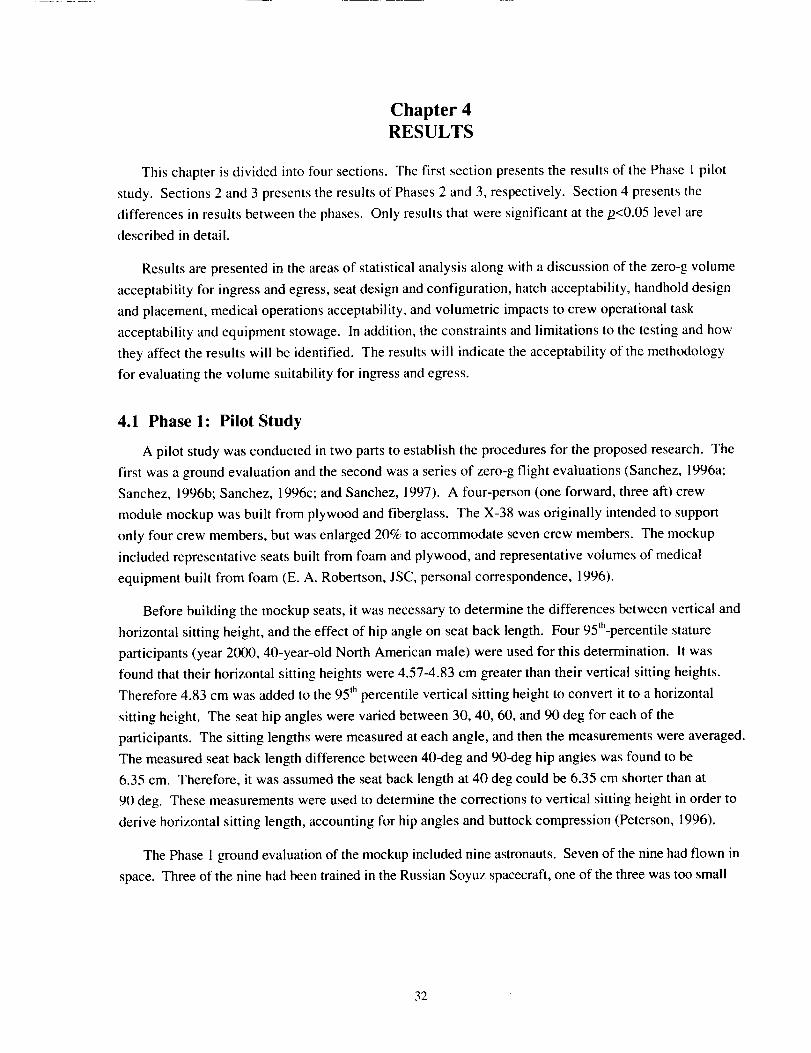
Chapter 4RESULTS
This chapter is divided into four sections. The first section presents the results of the Phase 1 pilot
study. Sections 2 and 3 presents the results of Phases 2 and 3, respectively. Section 4 presents the
differences in results between the phases. Only results that were significant at the/2<0.05 level are
described in detail.
Results are presented in the areas of statistical analysis along with a discussion of the zero-g volume
acceptability for ingress and egress, seat design and configuration, hatch acceptability, handhold design
and placement, medical operations acceptability, and volumetric impacts to crew operational task
acceptability and equipment stowage. In addition, the constraints and limitations to the testing and how
they affect the results will be identified. The results will indicate the acceptability of the methodology
for evaluating the volume suitability for ingress and egress.
4.1 Phase 1: Pilot Study
A pilot study was conducted in two parts to establish the procedures for the proposed research. The
first was a ground evaluation and the second was a series of zero-g flight evaluations (Sanchez, 1996a;
Sanchez, 1996b; Sanchez, 1996c; and Sanchez, 1997). A four-person (one forward, three aft) crew
module mockup was built from plywood and fiberglass. The X-38 was originally intended to support
only four crew members, but was enlarged 20% to accommodate seven crew members. The mockup
included representative seats built from foam and plywood, and representative volumes of medical
equipment built from foam (E. A. Robertson, JSC, personal correspondence, 1996).
Before building the mockup seats, it was necessary to determine the differences between vertical and
horizontal sitting height, and the effect of hip angle on seat back length. Four 95th-percentile stature
participants (year 2000, 40-year-old North American male) were used for this determination. It was
found that their horizontal sitting heights were 4.57-4.83 cm greater than their vertical sitting heights.
Therefore 4.83 cm was added to the 95 Ihpercentile vertical sitting height to convert it to a horizontal
sitting height. The seat hip angles were varied between 30, 40, 60, and 90 deg for each of the
participants. The sitting lengths were measured at each angle, and then the measurements were averaged.
The measured seat back length difference between 40-deg and 90-deg hip angles was found to be
6.35 cm. Therefore, it was assumed the seat back length at 40 deg could be 6.35 cm shorter than at
90 deg. These measurements were used to determine the corrections to vertical sitting height in order to
derive horizontal sitting length, accounting for hip angles and buttock compression (Peterson, 1996).
The Phase 1 ground evaluation of the mockup included nine astronauts. Seven of the nine had flown in
space. Three of the nine had been trained in the Russian Soyuz spacecraft, one of the three was too small
32
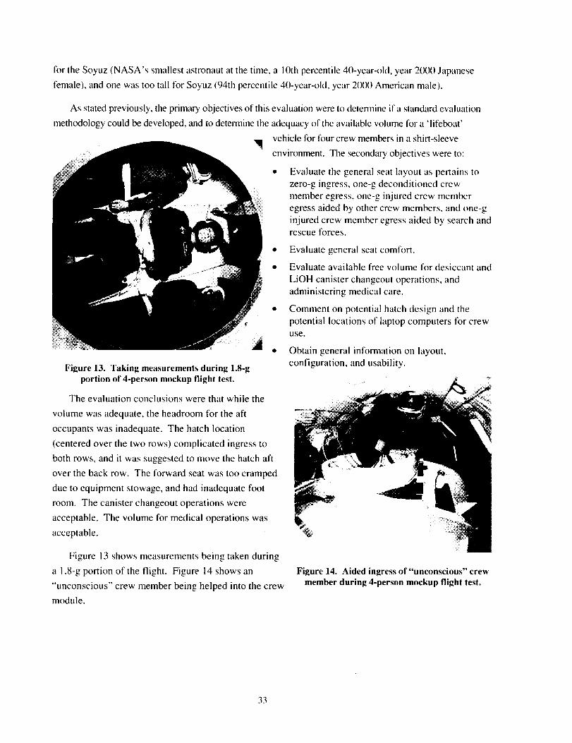
for the Soyuz (NASA's smallest astronaut at the time, a 10th percentile 40-year-old, year 2(X)0 Japanese
female), and one was too tall for Soyuz (94th percentile 40-year-old, year 2(X)0 American male).
As stated previously, the primary objectives of this evaluation were to detemline if a standard evaluation
methodology could be developed, and to determine the adequacy of the available volume lor a 'lifeboat'
' 4 •
Figure 13. Taking measurements during 1.8-gportion of 4-person moekup flight test.
The evaluation conclusions were that while the
volume was adequate, the headroom for the aft
occupants was inadequate. The hatch location
(centered over the two rows) complicated ingress to
both rows, and it was suggested to move the hatch aft
over the back row. The forward seat was too cramped
due to equipment stowage, and had inadequate foot
room. The canister changeout operations were
acceptable. The volume for medical operations was
acceptable.
Figure 13 shows measurements being taken during
a 1.8-g portion of the flight. Figure 14 shows an
"unconscious" crew member being helped into the crew
module.
vehicle for four crew members in a shirt-sleeve
environment. The secondary objectives were to:
• Evaluate the general seat layout as pertains to
zero-g ingress, one-g deconditioned crew
member egress, one-g injured crew member
egress aided by other crew members, and one-g
injured crew member egress aided by search andrescue forces.
Evaluate general seat comfort.
Evaluate available free volume for desiccant and
LiOH canister changeout operations, and
administering medical care.
Comment on potential hatch design and the
potential locations of laptop computers for crewuse.
Obtain general information on layout,
configuration, and usability.
Figure 14. Aided ingress of "unconscious" crewmember during 4-person mockup flight test.
33
4.1.1 Results From Pilot Study
The pilot study provided valuable information that was incorporated into the seven-person mockup
evaluations. Lessons learned include improvements to the: (1) test conduction and format, (2) test procedures,
(3) postflight questionnaires, (4) hatch locations, (5) seat design, (6) helmet choice, (7) stowage, and (8)
mockup construction. Specific results are detailed below (R. Husband, JSC, personal correspondence, 1996).
4.1.1.1 Zero-g Ingress and Egress
Zero-g ingress of four crew members could be accomplished in less than 20 seconds, starting at the
hatch and stopping when stabilized in the seat. The optimum ingress order for a four-person vehicle was
determined to be the forward seat first, the two outer aft seats second and third, and the center aft seat
last. The front seat leg and foot room was found to be unacceptable. The water tanks located inside the
crew module interfered with ingress to the front seats and it was determined that they should be moved or
shaped confomal to the wall (the water tanks were not in the crew volume for the seven-person vehicle).
The zero-g change-out of LiOH canisters was acceptable. The adjustable seat was desirable. It was also
determined that more work needs to be done on seat design, especially in the thigh adjustment area.
4.1.1.2 Seat Configuration
The front seat was found to be optimal for the primary crew controls and vehicle interfaces due to the
aft seats being needed for ill or injured crew members. It was also determined that an additional set of crew
controls should be accessible by a crew member in the aft row. The two outside seats on the aft row were
preferred for the ill or injured crew member, with the crew medical officer in the middle seat next to them.
It was actually possible to fit four crew members in the aft row of seats, depending on seat design.
4.1.1.3 Hatch
The hatch location (moved aft from the initial ground test) was acceptable. The inward opening
hatch appeared to be acceptable. An alternate egress path was recommended.
4.1.1.4 Handholds
The number and location of handholds was generally acceptable, but rigid ones instead of cloth loops
were indicated as preferable.
4.1.1.5 Crew Volume
The available crew volume was generally acceptable as tested, along with proposed stowage locations for
medical equipment. It was understood that this volume would decrease as more crew equipment is defined.
4.1.1.6 Helmets
Aircraft-type helmets were preferred to clamshell helmets due to the restricted visibility of the clamshells.
The clamshell helmets were those used in the early Space Shuttle Program and have a face seal covered by a visor.
34
4.1.1.7 Constraints" and Limitations
The final seat design, with a stroke for load attenuation, would almost certainly decrease the overall
crew volume. Additional crew equipment was not represented, and its stowage would decrease the
overall crew volume. Any decrease in crew volume would require additional evaluations. The zero-g
and high-g test environments were evaluated during relatively short periods of time. A longer period of
time for evaluating the dynamic environment (excluding the zero-g) could be obtained using a centrifuge.
A longer evaluation in one g would permit further evaluation of volume to ensure it is not claustrophobic
and to evaluate seat comfort. One-g egress could not be fully evaluated since the exterior of the vehicle
was not represented and since the hatch was not at the actual height above ground.
4.1.2 Application of Pilot Study Results
The results from this pilot study demonstrated that valuable human factors evaluation data could be
obtained from a combination of ground and flight tests. The one-g environment allowed the flight
procedures to be practiced and modified as appropriate, and the general mockup to be evaluated for
suitability before committing to an expensive flight test. The zero-g and 1.8-g environments obtained
from the KC-135 provided a unique test environment to examine issues such as ingress, egress,
maneuverability, volume acceptability, and operations in dynamic environments. The data obtained from
the pilot study were directly applied to the development of the evaluation methodology, test objectives,
protocol and questionnaires: and to improve the final mockup design and layout.
4.2 Phase 2
Phase 2 included data collection of timed zero-g ingress and egress of healthy and simulated injured
crew members using the seven-person mockup at full and reduced volume. The same ingress and egress
tests were performed on all three flights. The volume reduction was accomplished by placing 6-inch-
thick pads on all the seats. Data analysis was only conducted on the performance variables.
4.2.1 Performance Variables
The testing for normality showed that all Phase 2 performance variables with three or more data
points were normally distributed. These normally distributed data include zero-g ingress times for
healthy crew members in both fixed and random orders, and zero-g egress times. Insufficient data points
were available on ingress times of a seven-member crew with one ill crew member, and of a four-member
crew with one ill crew member. Both of these tests only had two data points each. Table 10 shows the
ANOVA R-values for the variables.
The ANOVAs showed that there were no significant differences between the normally distributed
performance variables, including the comparisons of full volume versus reduced volume. Table 1I
shows the statistical data for the variables. The evaluators were able to meet the three-minute ingress
35
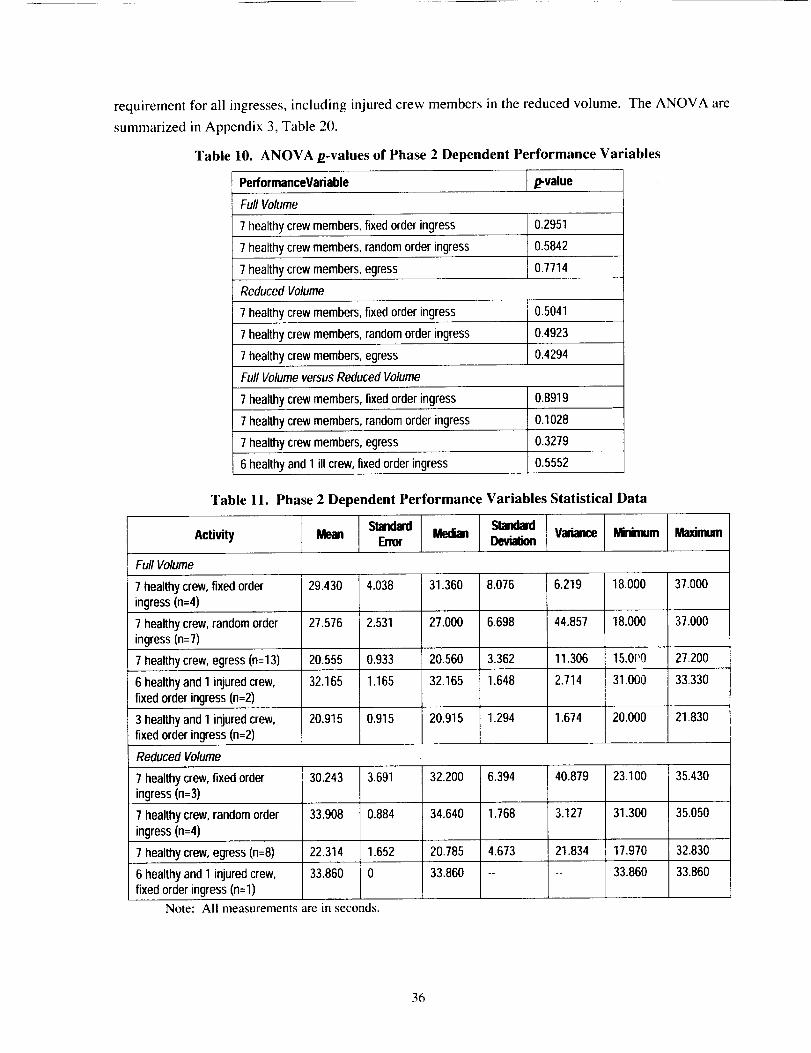
requirement for all ingresses, including injured crew members in the reduced volume. The ANOVA are
summarized in Appendix 3, Table 20.
Table 10. ANOVA/z-values of Phase 2 Dependent Performance Variables
PerformanceVariable D-value
Full Volume
7 healthy crew members, fixed order ingress
7 healthy crew members, random order ingress
7 healthy crew members, egress
Reduced Volume
7 healthy crew members, fixed order ingress
7 healthy crew members, random order ingress
7 healthy crew members, egress
Full Volume versus Reduced Volume
7 healthy crew members, fixedorder ingress
7 healthy crew members, random order ingress
7 healthy crew members, egress
6 healthy and 1 ill crew, fixed order ingress
0.2951
0.5842
0.7714
0.5041
0.4923
0.4294
0.8919
0.1028
0.3279
0.5552
Table 11. Phase 2 Dependent Performance Variables Statistical Data
Median Standard Va_ianN_e _ MaxinJmActivity Mean Error Deviation
FurlVolume
7 healthycrew, fixed order 29.430 4.038 31.360 8.076 6.219 18.000 37.000
ingress(n=4)
7 healthy crew,random order 27.576 2,531 27.000 6.698 44.857 18.000 37.000
ingress(n=7)
7 healthycrew, egress (n=l 3) 20.555 0.933 20.560 3.362 11.306 15.0('0 27.200
6 healthy and 1 injured crew, 32.165 1.165 32.165 1.648 2.714 31.000 33.330
fixedorder ingress (n=2)
20.915 0.915 20.915 1.294 1.674 20.000 21.8303 healthy and 1 injuredcrew,
fixed order ingress (n=2)
Reduced Volume
7 healthy crew, fixed order 30.243 3.691 32.200 6.394 40.879 23.100 35.430
ingress (n=3)
7 healthy crew, random order 33.908 0.884 34.640 1.768 3.127 31.300 35.050
ingress (n=4)
7 healthy crew, egress (n=8) 22.314 1.652 20.785 4.673 21.834 17.970 32.830
33.860 0 33.860 .... 33.860 33.8606 healthy and 1 injured crew,
fixed order ingress (n=l)
Note: All measurements are in seconds.
36
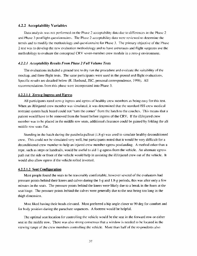
4.2.2 Acceptability Variables
Data analysis was not performed on the Phase 2 acceptability data due to differences in the Phase 2
and Phase 3 postflight questionnaires. The Phase 2 acceptability data were reviewed to determine the
trends and to modify the methodology and questionnaire for Phase 3. The primary objective of the Phase
2 test was to develop the new evaluation methodology and to have astronauts and flight surgeons use the
methodology to evaluate the conceptual CRV seven-member crew module in a zero-g environment.
4.2.2.1 Acceptability Results From Phase 2 Full Volume Tests
The evaluations included a ground test to dry run the procedure and evaluate the suitability of the
mockup, and three flight tests. The same participants were used in the ground and flight evaluations.
Specific results are detailed below (R. Husband, JSC, personal correspondence, 1998). All
recommendations from this phase were incorporated into Phase 3.
4.2.2.1.1 Zero-g Ingress and Egress
All participants rated zero-g ingress and egress of healthy crew members as being easy for this test.
When an ill/injured crew member was simulated, it was determined that the standard ISS crew medical
restraint system back board could not "turn the corner" from the hatch to the couches. This means that a
patient would have to be removed from the board before ingress of the CRV. If the ill/injured crew
member was to be placed in the middle row seats, additional clearance could be gained by folding the aft
middle row seats flat.
Standing in the hatch during the parabola pullout (1.8-g) was used to simulate healthy deconditioned
crew. This could not be simulated very well, but participants noted that it would be very difficult for a
deconditioned crew member to help an injured crew member egress postlanding. A method other than a
rope, such as steps or handrails, would be useful to aid 1-g egress from the vehicle. An alternate egress
path out the side or front of the vehicle would help in assisting the ill/injured crew out of the vehicle. It
would also allow egress if the vehicle rolled inverted.
4.2.2.1.2 Seat Configuration
Most people found the seats to be reasonably comfortable, however several of the evaluators had
pressure points behind their knees and calves during the 1-g and 1.8-g periods, this was after only a few
minutes in the seats. The pressure points behind the knees were likely due to a break in the foam at the
seat hinge. The pressure points behind the calves were generally due to the seat being too long in the
thigh dimension.
Most liked having their heads elevated. Most preferred a hip angle closer to 90 deg for comfort and
for body position during the parachute sequences. A footrest would be helpful.
The optimal seat location for controlling the vehicle would be the seat in the forward row or either
seat in the middle row. There was also strong consensus that a window is needed to be located in the
viewing range of the crew members controlling the vehicle. More than half of the respondents also
37
thoughttheforwardandmiddlerowseatswouldbebestfor theill/injured crew member. This was
primarily due to the extra room around these seats.
4.2.2.1.3 Hatch
The presence of the hatch over the aft row middle seats prevents crew displays to be matched to the
eye points for these seats. The hatch also limits the stowage of medical equipment directly overhead an
ill/injured crew member, and reduced available volume for cardiopulmonary resuscitation.
It would be better if the hatch structure inside the crew compartment could be minimized or
eliminated. Additionally it would be better to move the hatch forward of its current location if the
structural design will support the change. This would allow using the full volume of the aft seats for
either controlling the vehicle or for medical procedures, as well as making the egress path more centrally
located. It was subsequently determined to be a significant impact to the structural design to move the
hatch with limited benefit.
4.2.2.1.4 Handholds
The handholds that were evaluated were soft, flexible loops attached at one point. There was near
unanimous consensus that the handholds should be attached at two points instead of one. This would
allow for better body position control in zero g. Opinions were split on whether the handholds should be
soft straps or solid handrails. The handholds should contrast in color to aid in visibility. Placement was
generally good, with only minor adjustments needed.
4.2.2.1.5 Medical Operations
No problems were noted with regard to reaching the medical equipment (simulated by foam core
boxes), but some equipment interfered with the occupants in the outside seats of the aft row. Better
stowage locations and methods were defined after the evaluation. Medical care was easiest in the
forward and middle rows where there is the greatest volume around the seats.
4.2.2.1.6 Displays
The outside video feed to the displays was well liked. The evaluators noticed no discomfort or
disorientation while watching the displays during the parabolas. This type of system can provide
excellent situational awareness when a forward-looking window is not available.
There was near unanimous consensus that the laptop screen size was too small for the corresponding
distance it was viewed from. Additionally, the laptop was too far away for some of the evaluators to
reach. The display was also unreadable due to vibration during portions of the flight. The large
projected display size was better in that it was easier to read and could be seen from adjacent seats.
Many found the goggle design that was tested uncomfortable, and not suitable for use while lying down
due to protrusions on the headband. The goggles received mixed reviews with some evaluators
perceiving a sharp display and some an out of focus display. Several crew members did not like the
goggles because only one person could view the display at a time, which makes it difficult to discuss the
38
information on the display. This particular goggle design also required head movements to change
displays, which are undesirable during reentry due to the potential for vestibular upset.
The evaluators considered it essential that the vehicle be designed to allow control from at least two
seats. Enough displays are required to provide redundancy, and it is highly desirable that all crew
members be able to see at least one display to increase situational awareness. Hand controllers should be
available to manipulate the displays to avoid overhead reaches during g-loaded flight.
4.2.2.1.7 Crew Volume
Overall, the volume of the crew compartment in the configuration tested was adequate for seven crew
members. The seats in the forward and middle rows had the most room. There were interferences with
walls in the middle and aft row seats. Many evaluators' feet penetrated the imaginary bulkhead in front
of the forward row, even those of small stature. The outside seats in the aft row have very cramped knee
room, and the evaluators' knees protruded through the viewing window. The feet of taller evaluators in
the aft row also interfered with the heads of evaluators in the middle row. The hatch interfered with the
heads of the crew in the middle seats of the aft row.
The seat interferences were addressed by shifting the middle seats in the aft row forward to clear the
hatch, angling the outer seats in the aft row to increase shoulder and knee clearance, changing the hip and
knee angles to increase foot clearance, and angling the seats in the middle row to increase head clearance.
Several CRV systems boxes located on the aft bulkhead interfered with the heads of the crew in the
aft row. This equipment was subsequently moved to below the seat line. Large boxes of medical
equipment interfered with the shoulders of crew in the outside seats of the aft row. This equipment was
subsequently broken into small packages that could be more easily stowed. The evaluators also
questioned whether there was enough volume to stow all other items needed. Additional items that
should be stowed were identified. This stowage was included in Phase 3 testing.
4.2.2.1.8 Helmets
Most evaluators liked using helmets for communications, oxygen+ and head protection. The helmet
design should be lightweight and allow a large field of view. Three helmet designs were tested,
including aircraft, helicopter, and the original Shuttle clamshell helmets. Aircraft helmets were
considered adequate but not optimal. Clamshell helmets were considered inadequate due to the limited
field of view. Not enough data were gathered on the helicopter helmets to make a judgement.
4.2.2.1.9 Constraints and Limitations
Changes in layout and stowage may affect acceptability ratings. A full-mission-duration ground test
should be performed to see what additional problems could be highlighted as a result of being in the
vehicle for nine hours. All necessary crew equipment was not represented in the stowage. A detailed list
of stowage items should be generated and represented in the next test.
39
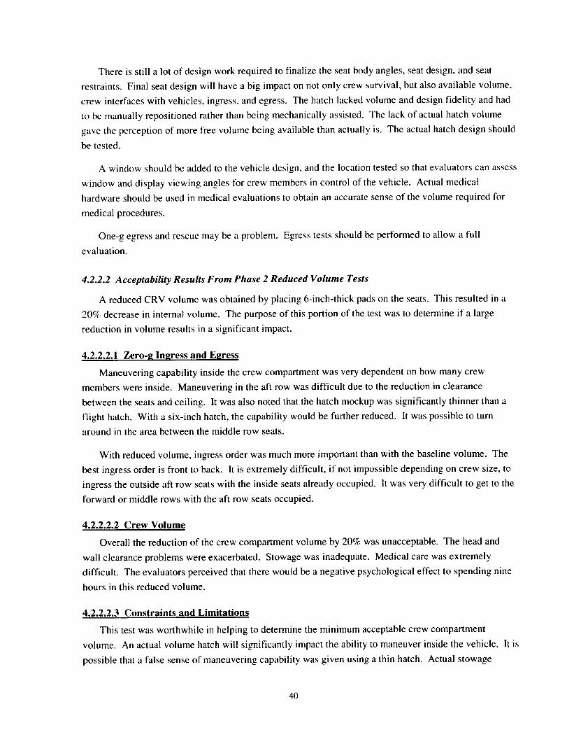
There is still a lot of design work required to finalize the seat body angles, seat design, and seat
restraints. Final seat design will have a big impact on not only crew survival, but also available volume,
crew interfaces with vehicles, ingress, and egress. The hatch lacked volume and design fidelity and had
to be manually repositioned rather than being mechanically assisted. The lack of actual hatch volume
gave the perception of more free volume being available than actually is. The actual hatch design should
be tested.
A window should be added to the vehicle design, and the location tested so that evaluators can assess
window and display viewing angles for crew members in control of the vehicle. Actual medical
hardware should be used in medical evaluations to obtain an accurate sense of the volume required for
medical procedures.
One-g egress and rescue may be a problem. Egress tests should be performed to allow a full
evaluation.
4.2.2.2 Acceptability Results From Phase 2 Reduced Volume Tests
A reduced CRV volume was obtained by placing 6-inch-thick pads on the seats. This resulted in a
20% decrease in internal volume. The purpose of this portion of the test was to determine if a large
reduction in volume results in a significant impact.
4.2.2.2.1 Zero-_ Ingress and E_ress
Maneuvering capability inside the crew compartment was very dependent on how many crew
members were inside. Maneuvering in the aft row was difficult due to the reduction in clearance
between the seats and ceiling. It was also noted that the hatch mockup was significantly thinner than a
flight hatch. With a six-inch hatch, the capability would be further reduced. It was possible to turn
around in the area between the middle row seats.
With reduced volume, ingress order was much more important than with the baseline volume. The
best ingress order is front to back. It is extremely difficult, if not impossible depending on crew size, to
ingress the outside aft row seats with the inside seats already occupied. It was very difficult to get to the
forward or middle rows with the aft row seats occupied.
4.2.2.2.2 Crew Volume
Overall the reduction of the crew compartment volume by 20% was unacceptable. The head and
wall clearance problems were exacerbated. Stowage was inadequate. Medical care was extremely
difficult. The evaluators perceived that there would be a negative psychological effect to spending nine
hours in this reduced volume.
4.2.2.2.3 Constraints and Limitations
This test was worthwhile in helping to determine the minimum acceptable crew compartment
volume. An actual volume hatch will significantly impact the ability to maneuver inside the vehicle. It is
possible that a false sense of maneuvering capability was given using a thin hatch. Actual stowage
4O
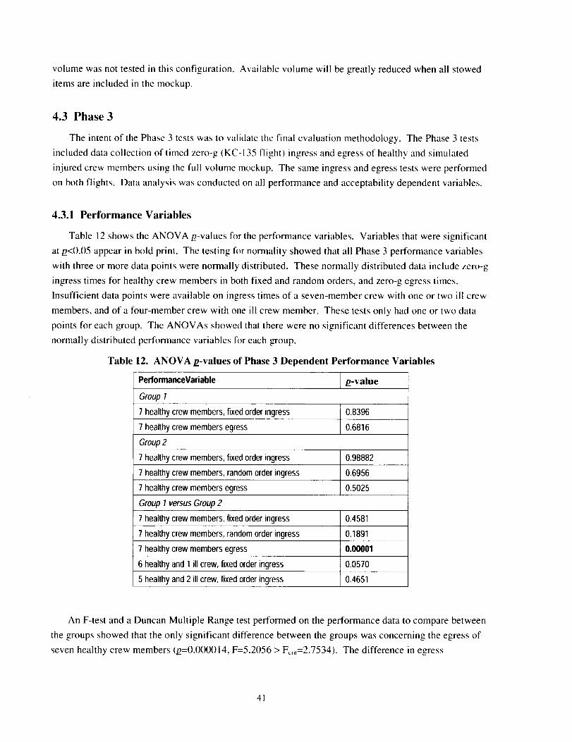
volume was not tested in this configuration. Available volume will be greatly reduced when all stowed
items are included in the mockup.
4.3 Phase 3
The intent of the Phase 3 tests was to validate the final evaluation methodology. The Phase 3 tests
included data collection of timed zero-g (KC-135 flight) ingress and egress of healthy and simulated
injured crew members using the full volume mockup. The same ingress and egress tests were performed
on both flights. Data analysis was conducted on all performance and acceptability dependent variables.
4.3.1 Performance Variables
Table 12 shows the ANOVA/2-values for the performance variables. Variables that were significant
at/2<0.05 appear in bold print. The testing for nomlality showed that all Phase 3 performance variables
with three or more data points were normally distributed. These normally distributed data include zero-g
ingress times for healthy crew members in both fixed and random orders, and zero-g egress times.
Insufficient data points were available on ingress times of a seven-member crew with one or two ill crew
members, and of a four-member crew with one ill crew member. These tests only had one or two data
points for each group. The ANOVAs showed that there were no significant differences between the
normally distributed performance variables for each group.
Table 12. ANOVA p-values of Phase 3 Dependent Performance Variables
PerformanceVariable .o-value
Group 1
7 healthy crew members, fixed order ingress 0.8396
7 healthy crew members egress 0.6816
Group 2
7 healthy crew members, fixed order ingress 0.98882
7 healthy crew members, random order ingress 0.6956
7 healthy crew members egress 0.5025
Group 1 versus Group 2
7 healthy crew members, fixed order ingress 0.4581
7 healthy crew members, random order ingress 0.1891
7 healthy crew members egress 0.00001
6 healthy and 1 illcrew, fixedorder ingress 0.0570
5 healthy and 2 illcrew, fixedorder ingress 0.4651
An F-test and a Duncan Multiple Range test performed on the performance data to compare between
the groups showed that the only significant difference between the groups was concerning the egress of
seven healthy crew members (/2=0.0(X)014, F=5.2056 > Fcn,=2.7534). The difference in egress
41
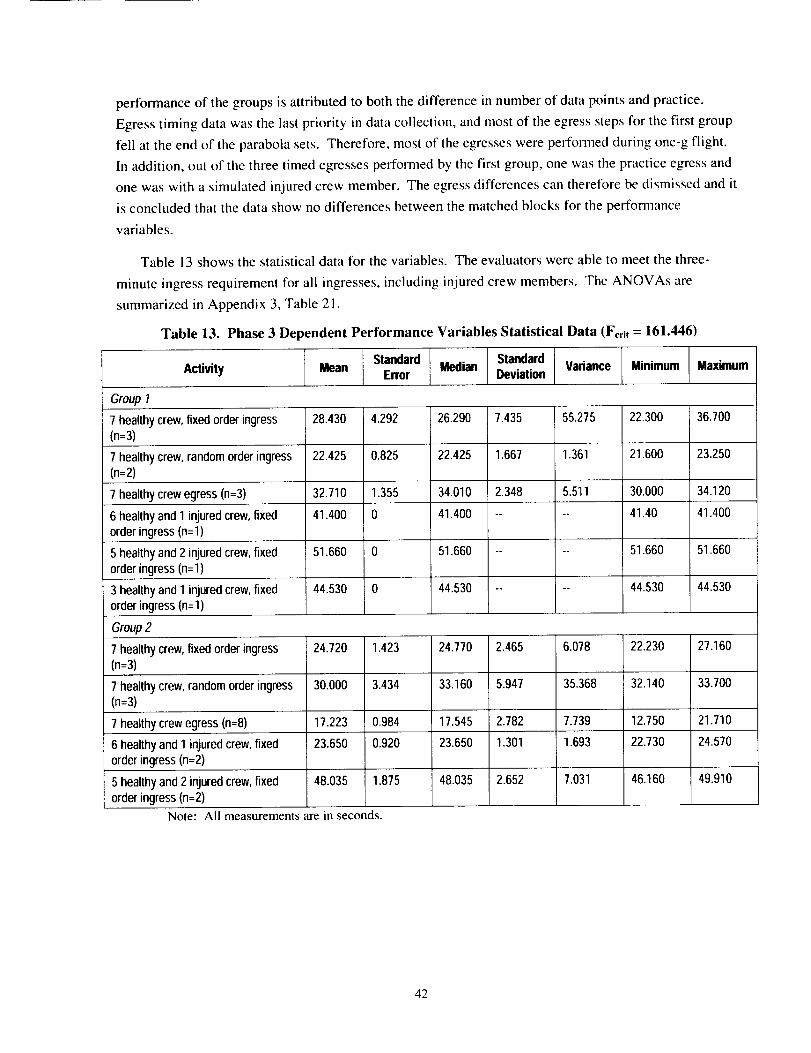
performanceof thegroupsisattributedto boththedifferenceinnumberofdatapointsandpractice.Egresstimingdatawasthelastpriorityindatacollection,andmostof theegressstepsfor thefirstgroupfell attheendof theparabolasets.Therefore,mostof theegresseswereperformedduringone-gflight.In addition,outof thethreetimedegressesperformedbythefirstgroup,onewasthepracticeegressandonewaswithasimulatedinjuredcrewmember.Theegressdifferencescanthereforebedismissedanditisconcludedthatthedatashownodifferencesbetweenthematchedblocksfor theperformancevariables.
Table13showsthestatisticaldatafor thevariables.Theevaluatorswereabletomeetthethree-
minuteingressrequirementfor all ingresses,includinginjuredcrewmembers.TheANOVAsaresummarizedinAppendix3,Table21.
Table 13. Phase 3 Dependent Performance Variables Statistical Data (For. = 161.446)
Standard Median Standard Variance Minimum MaximumActivity Mean Error Deviation
Group 7
7 healthy crew, fixed order ingress 28.430 4.292 26.290 7.435 55.275 22.300 36.700
(n=3)
7 healthy crew, random order ingress 22.425 0.825 22.425 1.667 1.361 21.600 23.250
(n:2)
7 healthy crew egress (n=3) 32.710 1.355 34.010 2.348 5.511 30.000 34.120
6 healthy and 1 injured crew, fixed 41.400 0 41.400 .... 41.40 41.400
order ingress (n=l)
5 healthy and 2 injured crew, fixed 51.660 0 51.660 .... 51.660 51.660
order ingress (n=l)
3 healthy and I injured crew, fixed 44.530 0 44.530 .... 44.530 44.530
order ingress (n=1)
Group 2
7 healthy crew, fixed order ingress 24.720 1.423 24.770 2.465 6.078 22.230 27.160(n=3)
7 healthy crew, random order ingress 30.000 3.434 33.160 5.947 35.368 32.140 33.700(n=3)
7 healthy crew egress (n=8) 17.223 0.984 17.545 2.782 7.739 12.750 21.710
6 healthy and 1 injured crew, fixed 23.650 0.920 23.650 1.301 1.693 22.730 24.570
order ingress (n=2)
48.035 1.875 48.035 2.652 7.031 46.160 49.9105 healthy and 2 injured crew, fixed
order ingress (n=2)
Note: All measurements are in seconds.
42
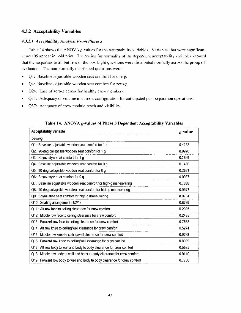
4.3.2 Acceptability Variables
4.3.2.1 Acceptability Analysis From Phase 3
Table 14 shows the ANOVA p-values for the acceptability variables. Variables that were significant
at/2<0.05 appear in bold print. Tile testing for normality of the dependent acceptability variables showed
that the responses to all but five of the postflight questions were distributed normally across the group of
evaluators. The non-normally distributed questions were:
• QI: Baseline adjustable wooden seat comfort for one-g.
• Q4: Baseline adjustable wooden seat comfort for zero-g.
• Q24: Ease of zero-g egress for healthy crew members.
• Q3 ! : Adequacy of volume in current configuration for anticipated post-separation operations.
• Q37: Adequacy of crew module reach and visibility.
Table 14. ANOVA £-values of Phase 3 Dependent Acceptability Variables
Acceptability Variable p-value
Seating
QI: Baseline adjustable wooden seat comfort for 1 g 0.4162
Q2: 90-deg collapsible wooden seat comfort for 1 g 0.9976
Q3: Soyuz-style seat comfort for 1 g 0.7699
Q4: Baseline adjustable wooden seat comfort for 0 g 0.1480
Q5: 90-deg collapsible wooden seat comfort for 0 g 0.3691
Q6: Soyuz-style seat comfort for 0 g 0.0967
Q7: Baseline adjustable wooden seat comfort for high-g maneuvering 0.7838
Q8: 90-deg collapsible wooden seat comfort for high-g maneuvering 0.9977
Q9: Soyuz-style seat comfort for high-g maneuvering 0.9704
Q10: Seating arrangement (41211) 0.8236
Q11: Aft row face to ceiling clearance for crew comfort 0.2925
Q12: Middle row face to ceiling clearance for crew comfort 0.2485
Q13: Forward row face to ceiling clearance for crew comfort 0.7882
Q14: Aft row knee to ceiling/wall clearance for crew comfort 0.5274
Q15: Middle row knee to ceiling/wall clearance for crew comfort 0.9268
Q16: Forward row knee to ceiling/wall clearance for crew comfort 0.8029
Q17: Aft row body to wall and body to body clearance for crew comfort 0.6695
Q18: Middle row body to wall and body to body clearance for crew comfort 0.9140
Q19: Forward row body to wall and body to body clearance for crew comfort 0.7760
43
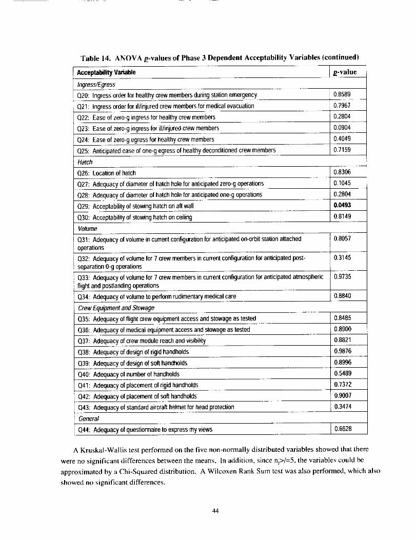
Table 14. ANOVA p-values of Phase 3 Dependent Acceptability Variables (continued)
Acceptability Variable g-value
Ingress/Egress
Q20: Ingress order for healthy crew members during station emergency 0.8589
Q21: Ingress order for ill/injured crew members for medical evacuation 0.7967
Q22: Ease of zero-g ingress for healthy crew members 0.2804
Q23: Ease of zero-g ingress for ill/injured crew members 0.0904
Q24: Ease of zero-g egress for healthy crew members 0.4049
Q25: Anticipated ease of one-g egress of healthy deconditioned crew members 0.7159
Hatch
Q26: Locationof hatch 0.8306
Q27: Adequacy of diameter of hatch hole for anticipated zero-g operations 0.1045
Q28: Adequacy of diameter of hatch hole for anticipated one-g operations 0.2804
Q29: Acceptability of stowing hatch on aft wall 0.0493
Q30: Acceptability of stowing hatch on ceiling 0.8149
Volume
Q31: Adequacy of volume in current configuration for anticipated on-orbit station attached
operations
O.8O57
Q32: Adequacy of volume for 7 crew members in current configurationfor anticipated post- 0.3145
separation 0-g operations
Q33: Adequacy of volume for 7 crew members in current configuration for anticipated atmospheric 0.9735
flight and postlanding operations
Q34: Adequacy of volume to perform rudimentary medical care 0.8840
Crew Equipment and Stowage
Q35: Adequacy of flight crew equipment access and stowage as tested 0.8485
Q36: Adequacy of medical equipment access and stowage as tested 0.8900
Q37: Adequacy of crew module reach and visibility 0.8821
Q38: Adequacy of design of rigid handholds 0.9876
1339: Adequacy of design of soft handholds 0.8996
Q40: Adequacy of number of handholds 0.5489
Q41: Adequacy of placement of rigid handholds 0.7372
Q42: Adequacy of placement of soft handholds 0.9007
Q43: Adequacy of standard aircraft helmet for head protection r 0.3474
General
(344: Adequacy of questionnaire to express my views 0.6628
A KruskaI-Wallis test performed on the five non-normally distributed variables showed that there
were no significant differences between the means. In addition, since nj>/=5, the variables could be
approximated by a Chi-Squared distribution. A Wilcoxen Rank Sum test was also performed, which also
showed no significant differences.
44
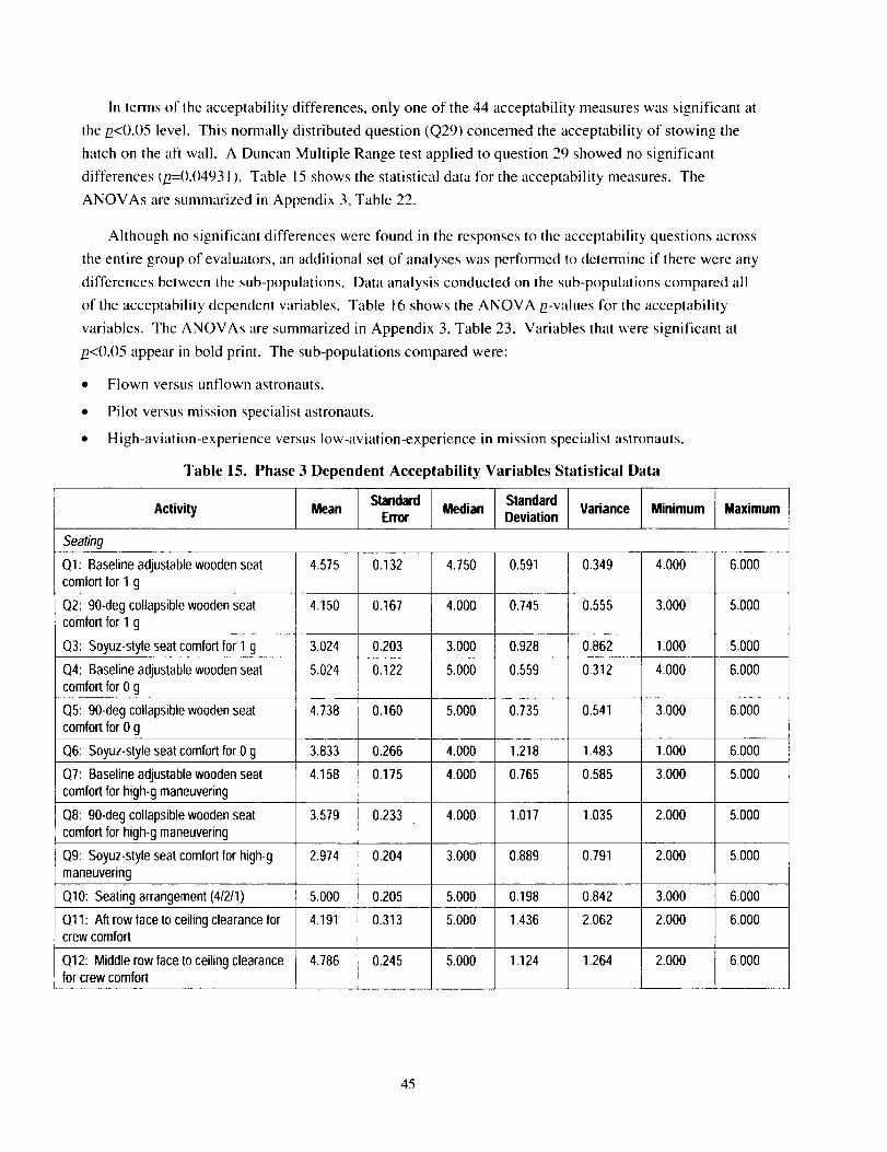
In termsof theacceptabilitydifferences,onlyoneof the44acceptabilitymeasureswassignificantatthe/2<0.05level.Thisnormallydistributedquestion(Q29)concernedtheacceptabilityof stowingthehatchontheaftwall. A DuncanMultipleRangetestappliedtoquestion29showednosignificantdifferences(/2=0.04931). Table 15 shows the statistical data for the acceptability measures. The
ANOVAs are summarized in Appendix 3, Table 22.
Although no significant differences were found in the responses to the acceptability questions across
the entire group of evaluators, an additional set of analyses was performed to deternaine if there were any
differences between the sub-populations. Data analysis conducted on the sub-populations cornpared all
of the acceptability dependent variables. Table 16 shows the ANOVA p-values for the acceptability
variables. The ANOVAs are summarized in Appendix 3, Table 23. Variables that were significant at
/2<0.05 appear in bold print. The sub-populations compared were:
• Flown versus unflown astronauts.
• Pilot versus mission specialist astronauts.
• High-aviation-experience versus low-aviation-experience in mission specialist astronauts.
Table 15. Phase 3 Dependent Acceptability Variables Statistical Data
Standard StandardActivity Mean Error Median Deviation Variance Minimum Maximum
Seatin9
QI: Baseline adjustable wooden seat 4.575 0.132 4.750 0.591 0.349 4.000 6.000
comfort for 1 g
Q2: 90-deg collapsible wooden seat 4.150 0.167 4.000 0.745 0.555 3.000 5.000
comfort for 1 g
Q3: Soyuz-style seat comfort for 1 g 3.024 0.203 3.000 0.928 0.862 1.000 5.000
Q4: Baseline adjustable wooden seat 5.024 0.122 5.000 0.559 0.312 4.000 6.000
comfort for 0 g
Q5: 90-deg collapsible wooden seat 4.738 0.160 5.000 0.735 0.541 3.000 6.000
comfort for 0 g
Q6: Soyuz-style seat comfort for 0 g 3.833 0.266 4.000 1.218 1.483 1.000 6.000
O7: Baseline adjustable wooden seat 4.158 0.175 4.000 0.765 0.585 3.000 5.000
comfort for high-g maneuvering
Q8: 90-deg collapsible wooden seat 3.579 0.233 4.000 1.017 1.035 2.000 5.000
comfort for high-g maneuvering
09: Soyuz-style seat comfort for high-g 2.974 0.204 3.000 0.889 0.791 2.000 5.000
maneuvering
1310: Seating arrangement (4/2/1) 5.000 0.205 5.000 0.198 0.842 3.000 6.000
Ql1: Aft row face to ceiling clearance for 4.191 0.313 5.000 1.436 2.062 2.000 6.000crew comfort
Q12: Middle row face to ceiling clearance 4.786 0.245 5.000 1.124 1.264 2.000 6.000for crew comfort
45
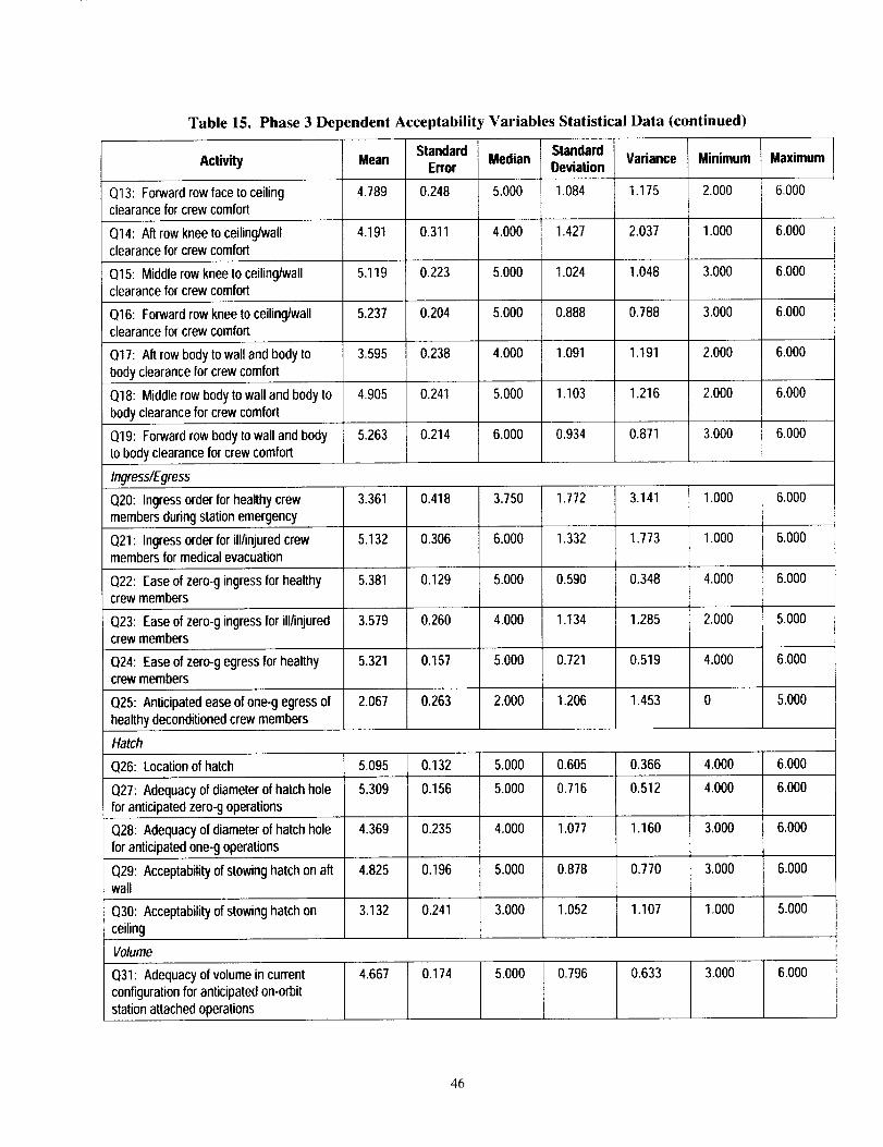
Table 15. Phase 3 Dependent Acceptability Variables Statistical Data (continued)
Mean Standard Median Standard Variance Minimum I MaximumActivity Error Deviation I
Q13: Forward row face to ceiling 4.789 0.248 5.000 1.084 1.175 2.000 6.000clearance for crew comfort
Q14: Aft row knee to ceiling/wall 4.191 0.311 4.000 1.427 2.037 1.000 6.000clearance for crew comfort
Q15: Middle row knee to ceiling/wall 5.119 0.223 5.000 1.024 1.048 3.000 6.000clearance for crew comfort
Q16: Forward row knee to ceiling/wall 5.237 0.204 5.000 0.888 0.788 3.000 6.000clearance for crew comfort
Q17: Aft row body to wall and body to 3.595 0.238 4.000 1.091 1.191 2.000 6.000
body clearance for crew comfort
Q18: Middle row body to wall and body to 4.905 0.241 5.000 1.103 1.216 2.000 6.000
body clearance for crew comfort
5.263 0.214 6.000 0.934 0.871 3.000 6.000Q19: Forward rowbody to wall and body
to body clearance for crew comfort
Ingress/Egress
Q20: Ingress order for healthy crew 3.361 0.418 3.750 1.772 3.141 1.000 6.000
members during station emergency
Q21: Ingress order for ill/injured crew 5.132 0.306 6.000 1.332 1373 1.000 6.000members for medical evacuation
Q22: Ease of zero-g ingress for healthy 5.381 0.129 5.000 0.590 0.348 4.000 6.000crew members
Q23: Ease of zero-g ingress for ill/injured 3.579 0.260 4.000 1.134 1.285 2.000 5.000crew members
Q24: Ease of zero-g egress for healthy 5.321 0.157 5.000 0.721 0.519 4.000 6.000crew members
Q25: Anticipated ease of one-g egress of 2.067 0.263 2.000 1.206 1.453 0 5.000
healthy deconditioned crew members
Hatch
Q26: Location of hatch 5.095 0.132 5.000 0.605 0,366 4.000 6.000
Q27: Adequacy of diameter of hatch hole 5.309 0.156 5.000 0.716 0.512 4.000 6.000
for anticipated zero-g operations
Q28: Adequacy of diameter of hatch hole 4.369 0.235 4.000 1.077 1.160 3.000 6.000
for anticipated one-g operations
Q29: Acceptability of stowing hatch on aft 4.825 0.196 5.000 0,878 0.770 3.000 6.000wall
Q30: Acceptability of stowing hatch on 3.132 0.241 3.000 1.052 1.107 1.000 5.000
ceiling
Volume
4.667 0.174 5.000 0.796 0.633 3.000 6.000£131: Adequacy of volume in current
configuration for anticipated on-orbitstation attached operations
46
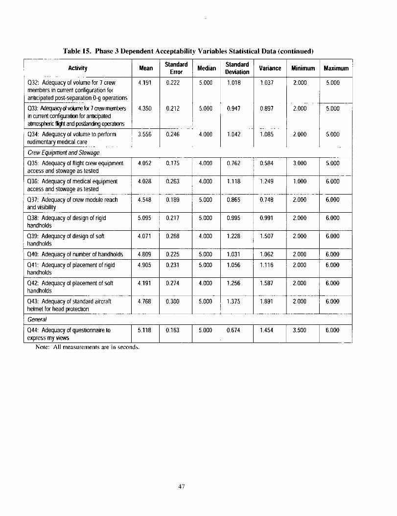
Table 15. Phase 3 De _endent Acceptability Variables Statistical Data (continued)
Standard StandardActivity Mean Error Median Deviation Variance Minimum Maximum
Q32: Adequacy of volume for 7 crew 4.191 0.222 5.000 1.018 1.037 2.000 5.000
members in current configuration foranticipated post-separation O-goperations
Q33: Adequacyofvolumefo_7 crewmernbers 4.350 0.212 5.000 0.947 0.897 2.000 5.000
in current configurationfor anticipated
almosphericflightandpostlandingoperations
Q34: Adequacy of volume to perform 3.556 0.246 4.000 1.042 1.085 2.000 5.000
rudimentary medical care
Crew Equipment and Stowage
Q35: Adequacy of flight crew equipment 4.052 0.175 4.000 0.762 0.584 3.000 5.000
access and stowage as tested
Q36: Adequacy of medical equipment 4.028 0.263 4.000 1.118 1.249 1.000 6.000
access and stowage as tested
Q37: Adequacy of crew module reach 4.548 0.189 5.000 0.865 0.748 2.000 6.000
and visibility
Q38: Adequacy of design of rigid 5.095 0.217 5.000 0.995 0.991 2.000 6.000handholds
Q39: Adequacy of design of soft 4.071 0.268 4.000 1.228 1.507 2.000 6.000handholds
Q40: Adequacy of number of handholds 4.809 0.225 5.000 1.031 1.062 2.000 6.000
Q41: Adequacy of placement of rigid 4.905 0.231 5.000 1.056 1.116 2.000 6.000handholds
Q42: Adequacy of placement of soft 4.191 0.274 4.000 1.256 1.587 2.000 6.000handholds
Q43: Adequacy of standard aircraft 4.768 0.300 5.000 1.375 1.891 2.000 6.000
helmet for head protection
General
Q44: Adequacy of questionnaire to 5.118 0.163 5.000 0.674 1.454 3.500 6.000express my views
Note: All measurements are in seconds.
47
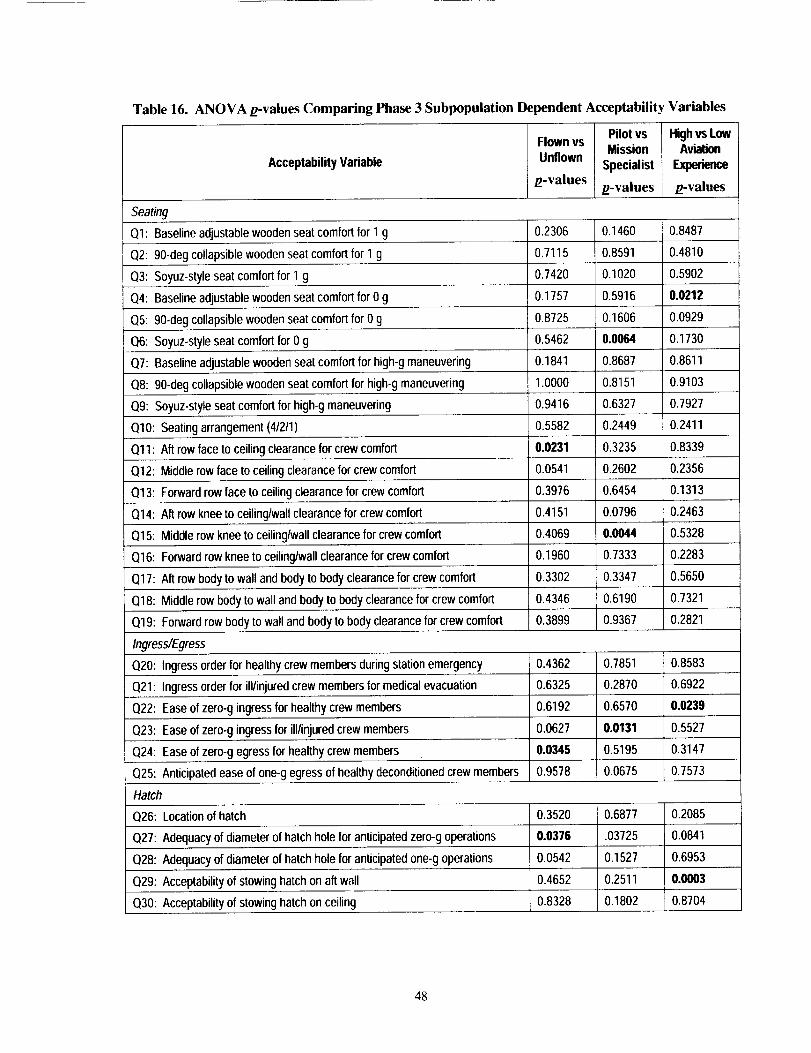
Table 16. ANOVA g-values Comparing Phase 3 Subpopulation Dependent Acceptability Variables
Acceptability Variable
Flown vs
Unflown
g-values
Pilot vs
Mission
Specialist
g-values
High vs LowAviation
g-values
Seating
Ol: Baseline adjustable wooden seat comfort for 1 g 0.2306 0.1460 0.8487
Q2: 90-deg collapsible wooden seat comfort for 1 g 0.7115 0.8591 0.4810
0.7420 0.1020 0.5902Q3: Soyuz-styleseat comfort for 1 g
Q4: Baselineadjustable wooden seat comfort for 0 g
Q5: 90-deg collapsible wooden seat comfort for 0 g
Q6: Soyuz-style seat comfort for 0 g
QT: Baseline adjustable wooden seat comfort for high-g maneuvering
Q8: 90-deg collapsible wooden seat comfort for high-g maneuvering
Q9: Soyuz-style seat comfort for high-g maneuvering
Q10: Seating arrangement (41211)
Qll: Aft row face to ceiling clearance for crew comfort
Q12: Middle row face to ceiling clearance for crew comfort
Q13: Forward row face to ceiling clearance for crew comfort
Q14: Aft row knee to ceiling/wall clearance for crew comfort
Q15: Middle row knee to ceiling/wall clearance for crew comfort
0.1757 0.5916 0.0212
0.8725 0.1606 0.0929
0.5462 0.0064 0.1730
0.1841 0.8687 0.8611
1.0000 0.8151 0,9103
0.9416 0.6327 0.7927
0.5582 0.2449 0.2411
0.0231 0.3235 0.8339
0.0541 0.2602 0.2356
0.3976 0.6454 0.1313
0.4151 0,0796 0.2463
0.4069 0.0044 0.5328
0.2283Q16: Forward rowknee to ceiling/wallclearance for crew comfort 0,1960 0.7333
Q17: Aft row body to wall and body to body clearance for crewcomfort 0,3302 0.3347 0.5650
Q18: Middle row body to wall and body to body clearance for crew comfort 0.4346 0.6190 0.7321
Q19: Forward row body to wall and body to body clearance for crew comfort 0.3899 0.9367 0.2821
Ingress�Egress
0.4362 0.7851 0.8583Q20: Ingress order for healthy crew members during stationemergency
Q21: Ingress order for ill/injured crew members for medical evacuation
Q22: Ease of zero-g ingress for healthy crew members
0.6325 0.2870 0.6922
0.6192 0.6570 0.0239
0.5527Q23: Ease of zero-g ingress for ill/injured crew members 0.0627 0.0131
Q24: Ease of zero-g egress for healthy crew members 0.0346 0,5195 0.3147
Q25: Anticipated ease of one-g egress of healthy deconditioned crew members 0.9578 0.0675 0.7573
Hatch
Q26: Location of hatch 0.3520 0.6877 0.2085
Q27: Adequacy of diameter of hatch hole for anticipated zero-g operations 0.0376 .03725 0.0841
Q28: Adequacy of diameter of hatch holefor anticipatedone-g operations 0.0542 0.1527 0.6953
Q29: Acceptability of stowing hatch on aft wall 0.4652 0.2511 0.0003
Q30: Acceptabilityof stowing hatch on ceiling 0.8328 0.1802 0.8704
48
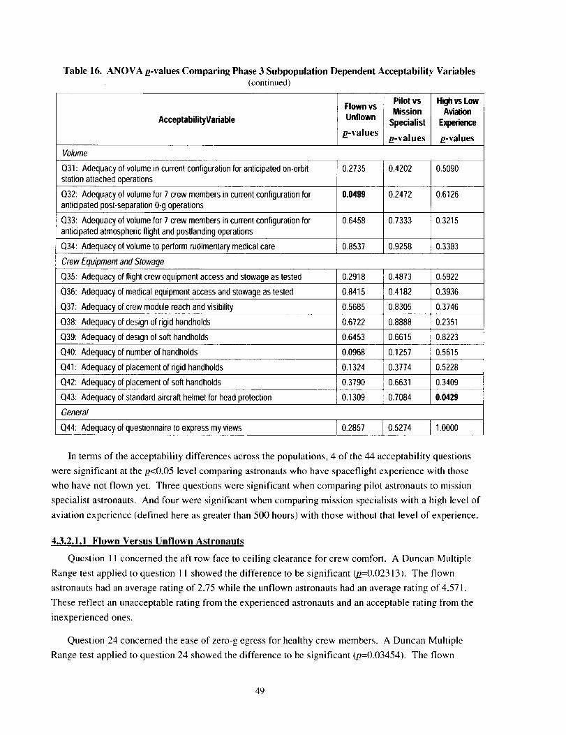
Table 16. ANOVA/t-values Comparing Phase 3 Subpopulation Dependent Acceptability Variables(continued)
AcceptabilityVariable
Flown vs
Unflown
/z-values
Pilot vs
Mission
Specialist
/z-values
Highvs LowAvialJon
Experience
/z-values
Volume
Q31: Adequacy of volume in current configuration for anticipated on-orbitstation attached operations
Q32: Adequacy of volume for 7 crew members in current configuration foranticipated post-separation 0-g operations
Q33: Adequacy of volume for 7 crew members in current configuration foranticipated atmospheric flight and postlanding operations
Q34: Adequacy of volume to perform rudimentary medical care
0.2735
0.0499
0.6458
0.8537
0.4202
0.2472
0.7333
0.9258
0.5090
0.6126
0.3215
0.3383
Crew Equipment and Stowage
Q35: Adequacy
Q36: Adequacy
Q37: Adequacy
Q38: Adequacy
Q39: Adequacy
of flight crew equipment access and stowage as tested
of medical equipment access and stowage as tested
of crew module reach and visibility
of design of rigid handholds
of design of soft handholds
Q40: Adequacy of number of handholds
Q41: Adequacy
Q42: Adequacy
Q43: Adequacy
of placement of rigid handholds
of placement of soft handholds
of standard aircraft helmet for head protection
0.2918
0.8415
0.5685
0.6722
0.6453
0.0968
0.1324
0.3790
0.1309
0.4873
0.4182
0.8305
0.8888
0.6615
0.1257
0.3774
0.6631
0.7084
0.5922
0.3936
0.3746
0.2351
0.8223
0.5615
0.5228
0.3409
0.0429
General
Q44: Adequacy of questionnaire to express my views I 0.2857 _ 0.5274 J 1.0000
In terms of the acceptability differences across the populations, 4 of the 44 acceptability questions
were significant at the/2<0.05 level comparing astronauts who have spaceflight experience with those
who have not flown yet. Three questions were significant when comparing pilot astronauts to mission
specialist astronauts. And four were significant when comparing mission specialists with a high level of
aviation experience (defined here as greater than 500 hours) with those without that level of experience.
4.3.2.1.1 Flown Versus Unflown Astronauts
Question 1 ! concerned the aft row face to ceiling clearance for crew comfort. A Duncan Multiple
Range test applied to question I I showed the difference to be significant (/2=0.02313). The flown
astronauts had an average rating of 2.75 while the unflown astronauts had an average rating of 4.571.
These reflect an unacceptable rating from the experienced astronauts and an acceptable rating from the
inexperienced ones.
Question 24 concerned the ease of zero-g egress for healthy crew members. A Duncan Multiple
Range test applied to question 24 showed the difference to be significant (/2=0.03454). The flown
49
astronauts had an average rating of 4.75 while the unflown astronauts had an average rating of 5.554.
The experienced astronauts considered the task to be easy, and the inexperienced astronauts very easy.
Question 27 concerned the adequacy of the diameter of the hatch hole for anticipated zero-g
operations. A Duncan Multiple Range test applied to question 27 showed the difference to be significant
(/2=0.03764). The flown astronauts had an average rating of 4.75 while the unflown astronauts had an
average rating of 5.536. The experienced astronauts considered the task to be adequate, and the
inexperienced astronauts completely adequate.
Question 32 concerned the adequacy of the volume for seven crew members in the current
configuration for anticipated post-separation zero-g operations. A Duncan Multiple Range test applied to
question 32 showed no significant difference (/2=0.04998). The flown astronauts had an average rating
of 3.375 while the unflown astronauts had an average rating of 4.536. The experienced astronauts
considered the task to be marginally adequate, and the inexperienced astronauts adequate.
The data reflects the role of spaceflight experience in understanding how a human really operates in
zero g. In the data points where differences were noted, and in all but 6 other of the 44 questions,
experienced crew members were more cautious in their answers and gave the tasks lower ratings than
inexperienced astronauts.
4.3.2.1.2 Pilot Versus Mission Specialist Astronauts
Question 6 concerned the Soyuz-seat comfort in zero g. A Duncan Multiple Range test applied to
question 6 showed the difference to be significant (/2=0.00636). The pilot astronauts had an average
rating of 2.6 while the mission specialist astronauts had an average rating of 4.346. These reflect an
uncomfortable rating from the pilots and a comfortable rating from the mission specialists.
Question 15 concerned the middle row knee to ceiling and wall clearance for crew comfort. A
Duncan Multiple Range test applied to question 15 showed no significant difference _=0.(X)44). The
pilot astronauts had an average rating of 5 while the mission specialist astronauts had an average rating of
5.038. These reflect an acceptable rating from both groups with the mission specialists slightly more
favorable.
Question 23 concerned the ease of zero-g ingress for ill or injured crew members. A Duncan
Multiple Range test applied to question 23 showed the difference to be significant (//=0.01321). The
pilot astronauts had an average rating of 2.6 while the mission specialist astronauts had an average rating
of 4. These reflect a difficult rating from the pilots and a marginally easy rating from the mission
specialists.
The data reflect the differing experience base and expected task requirements for pilot and mission
specialist astronauts. In these data points where differences were noted, and in all but 15 of the 44
questions, pilot astronauts were more cautious in their answers and gave the tasks lower ratings than
mission specialist astronauts.
5O
4.3.2.1.3 High-Aviation-Experience Versus Low-Aviation-Experience Mission Specialists
Question 4 concerned the baseline adjustable wooden seat comfort in zero-g. A Duncan Multiple
Range test applied to question 4 showed the difference to be significant (/2=0.02121 ). The high-aviation-
experience mission specialist astronauts had an average rating of 5.278 while the low-aviation-experience
mission specialist astronauts had an average rating of 4.5. These reflect a very comfortable rating from
the high-aviation-experience and a comfortable rating from the low-aviation-experience mission
specialists.
Question 22 concerned the ease of zero-g ingress for healthy crew members. A Duncan Multiple
Range test applied to question 22 showed a significant difference (/2=0.02387). The high-aviation-
experience mission specialist astronauts had an average rating of 5.313 while the low-aviation-experience
mission specialist astronauts had an average rating of 5. These reflect a very easy rating from the high-
aviation-experience and an easy rating from the low-aviation-experience mission specialists.
Question 29 concerned the acceptability of stowing the hatch on the aft wall. A Duncan Multiple
Range test applied to question 29 showed the difference to be significant (/2=0.00025). The high-
aviation-experience mission specialist astronauts had an average rating of 5.167 while the low-aviation-
experience mission specialist astronauts had an average rating of 3.5. These reflect a completely
acceptable rating from the high-aviation-experience and a marginally acceptable rating from the low-
aviation-experience mission specialists.
Question 43 concerned the adequacy of using standard aircraft helmets for head protection. A
Duncan Multiple Range test applied to question 43 showed a significant difference (/2=0.04298). The
high-aviation-experience mission specialist astronauts had an average rating of 5.389 while the low-
aviation-experience mission specialist astronauts had an average rating of 3.75. These reflect a
completely adequate rating from the high-aviation-experience and a marginally adequate rating from the
low-aviation-experience mission specialists.
The data reflects the differing experience bases for mission specialist astronauts with a high
experience level in aviation in comparison to those with little aviation experience. Those with the higher
levels of experience are familiar with and comfortable in a cockpit environment and typically are willing
to make due with less than optimal conditions for a "lifeboat." This was evident in the comments on the
postflight questionnaire, in the debriefings, and in their ratings on the questions. In those data points
where differences were noted, and in all but 4 other of the 44 questions, high-aviation-experience mission
specialist astronauts were more positive and accepting in their answers and gave the tasks higher ratings
than low-aviation-experience mission specialists.
4.3.2.2 Acceptability Results From Phase 3
The evaluations conducted in this phase included two ground tests to dry-run the procedure and
evaluate the suitability of the mockup, and two flight tests to gather data. The first ground test focused
on medical operations and the second on ingress and crew operations. The same participants were used
in the ground and flight tests. An overview of the parabolas is shown in Table 17. Specific results are
51
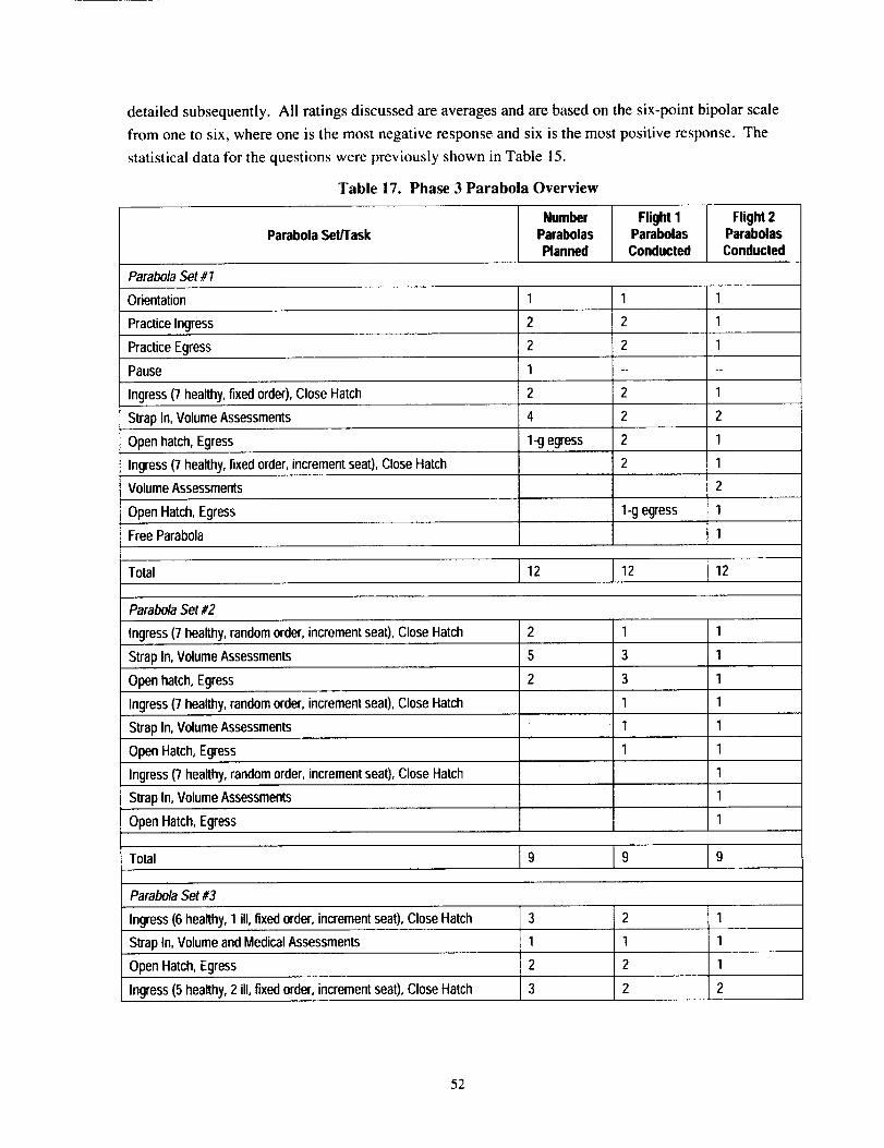
detailed subsequently. All ratings discussed are averages and are based on the six-point bipolar scale
from one to six, where one is the most negative response and six is the most positive response. The
statistical data for the questions were previously shown in Table 15.
Table 17. Phase 3 Parabola Overview
Number Flight I Flight 2Parabola Set/Task Parabolas Parabolas Parabolas
Planned Conducted Conducted
Parabola Set #1
Orientation 1 1 1
Practice Ingress 2 2 1
Practice Egress
Pause 1 ....
Ingress (7 healthy, fixed order), Close Hatch 2 2 1
Strap In, Volume Assessments 4 2 2
Open hatch, Egress 1-g egress 2 1
2 1Ingress(7 healthy, fixed order, increment seat), Close Hatch
Volume Assessments
1-g egress
2
1
1
Open Hatch, Egress
Free Parabola
Total 12 12 12
Parabola Set #2
Ingress (7 healthy, random order, increment seat), Close Hatch 2 1 1
Strap In, Volume Assessments 5 3 1
Open hatch, Egress 2 3 1
Ingress (7 healthy, random order, increment seat), Close Hatch 1 1
Strap In, Volume Assessments 1 1
Open Hatch, Egress 1 1
1Ingress(7 healthy, random order, increment seat), Close Hatch
Strap In, Volume Assessments
Open Hatch, Egress
Total
1
1
9 9 9
Parabola Set #3
Ingress (6 healthy, 1 ill, fixedorder, increment seat), Close Hatch
Strap In, Volume and Medical Assessments
Open Hatch, Egress
Ingress (5 healthy, 2 ill, fixed order, increment seat), Close Hatch
2 1
1 1
2 1
2 2
52
Table 17. Phase 3 Parabola Overview (continued)
Number Flight I Flight 2Parabola Set/Task Parabolas Parabolas Parabolas
Planned Conducted Conducted
Parabola Set #3, cont.
Strap In, Volume and Medical Assessments 1 2 1
Open hatch, Egress 2 1 plus 1-g 1
Ingress (5 healthy,2 ill, fixed order, increment seat), Close Hatch 2
Strap In, Volume and Medical Assessments 1
Open Hatch, Egress 1
Free Parabola 1
Total 12 10 12
Parabola Set #4
Ingress (3 healthy, 1 "dummy", fixed order), Close Hatch, Strap In 3 3 1-g ingress
Medical Evaluations 10 4 13
Open Hatch, Egress 1 eg[essIrombol- 1-g egresstomaccess
Ingress 1
Medical Evaluations 3
Egress 1
Ingress (3 healthy, 1 injured) 2
Medical Evaluations 2
Egress 1
Total 14 17 13
Flight Total 48 48 46
4.3.2.2.1 Zero-g Ingress and Egress
Participants rated zero-g ingress and egress of healthy crew members as being very easy for the
configuration tested (rated 5.4 and 5.3, respectively). Evaluators exhibited a natural tendency to ingress
the crew module feet first and to egress head first. It was noticeably more difficult to ingress and egress
when the two middle seats in the aft row were in the up position rather than being folded flat. Ease of
ingress of an ill or injured crew member was rated as marginal (3.6). It was noted that this task will be
exacerbated if the crew member is unconscious. It is difficult to control the mass and inertia of an
injured person without a backboard, and the standard station backboard will not fit through the hatch and
turn the corner into the seats. It is possible to injure a crew member worse during an aided ingress.
Ingress order was not considered to be particularly important for healthy crew members during a
station emergency (3.4). It is easiest to fill the vehicle from the forward row first. There is adequate
53
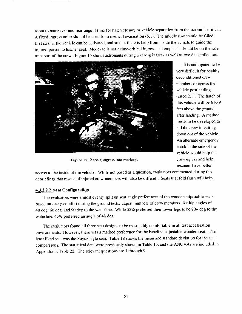
roomto maneuverandrearrangeif timefor hatchclosureor vehicleseparationfromthestationiscritical.A fixedingressordershouldbeusedfor amedicalevacuation(5.i ). Themiddlerowshouldbefilledfirst sothatthevehiclecanbeactivated,andsothatthereishelpfrominsidethevehicletoguidetheinjuredpersontohis/herseat.Medevacisnotatime-criticalingressandemphasisshouldbeonthesafetransportof thecrew. Figure15showsastronautsduringazero-gingressaswellastwodatacollectors.
It isanticipatedtobeverydifficult for healthydeconditionedcrewmemberstoegressthevehiclepostlanding(rated2.i). Thehatchofthisvehiclewill be6to 9
feetabovethegroundafterlanding.A methodneedstobedevelopedtoaidthecrewingettingdownoutof thevehicle.An alternateemergencyhatchin thesideof the
vehiclewouldhelptheFigure15.Zero-gingressintomockup, crewegressandhelp
rescuers have better
access to the inside of the vehicle. While not posed as a question, evaluators commented during the
debriefings that rescue of injured crew members will also be difficult. Seats that fold flush will help.
4.3.2.2.2 Seat Confi2uration
The evaluators were almost evenly split on seat angle preferences of the wooden adjustable seats
based on one-g comfort during the ground tests. Equal numbers of crew members like hip angles of
40 deg, 60 deg, and 90 deg to the waterline. While 55% preferred their lower legs to be 90+ deg to the
waterline, 45% preferred an angle of 40 deg.
The evaluators found all three seat designs to be reasonably comfortable in all test acceleration
environments. However, there was a marked preference for the baseline adjustable wooden seat. The
least liked seat was the Soyuz-style seat. Table 18 shows the mean and standard deviation for the seat
comparisons. The statistical data were previously shown in Table 15, and the ANOVAs are included in
Appendix 3, Table 22. The relevant questions are I through 9.
54
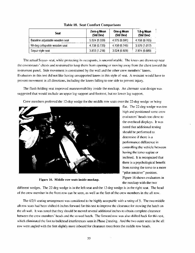
Table 18. Seat Comfort Com mrisons
Seat Zero-gMean One-gMean 1.8-gMean(Std Dev) (StdDev) (Std Dev)
Baselineadjustablewoodenseat 5.024(0.559) 4.575(0.591) 4.158(0.765)
90-degcollapsiblewoodenseat 4.738(0.735) 4.150(0.745) 3.579(1.017)
Soyuz-styleseat 3.833(1.218) 3.024(0.928) 2.974(0.889)
The actual Soyuz- seat, while protecting its occupants, is uncomfortable. The knees are drawn up near
the cosmonauts' chests and restrained to keep them from opening or moving away from the chest toward the
instrument panel. Side movement is constrained by the wall and the other crew members' knees.
Evaluators in this test did not like having unsupported knees in this style of seat. A restraint would have to
prevent movement in all directions, including the knees falling to one side to prevent injury.
The flush folding seat improved maneuverability inside the mockup. An alternate seat design was
suggested that would include an upper leg support and footrest, but no lower leg support.
Crew members preferred the 12-deg wedge for the middle row seats over the 22-deg wedge or being
flat. The 22-deg wedge was too
high and positioned some crew
evaluators' heads too close to
the overhead displays. It was
noted that additional testing
should be performed to
determine if there is a
performance difference in
controlling the vehicle between
having the torso supine or
inclined. It is recognized that
there is a psychological benefit
from raising the torso to a more
"pilot-intuitive" position.
Figure 16. Middle row seats inside mockup. Figure 16 shows evaluators inthe mockup with the two
different wedges. The 22-deg wedge is in the left seat and the 12-deg wedge is in the right seat. The head
of the crew member in the front row can be seen, as well as the feet of the crew members in the aft row.
The 4/2/1 seating arrangement was considered to be highly acceptable with a rating of 5. The two middle
aft row seats had been shifted 6 inches forward for this test to improve the clearance for stowing the hatch on
the aft wall. It was noted that they should be moved several additional inches to obtain complete clearance
between the crew members' heads and the stowed hatch. The forward row was also shifted back for this test,
which eliminated the foot to bulkhead interferences seen in Phase 2 testing. And the two outer seats in the aft
row were angled with the feet slightly more inboard for clearance room from the middle row heads.
55
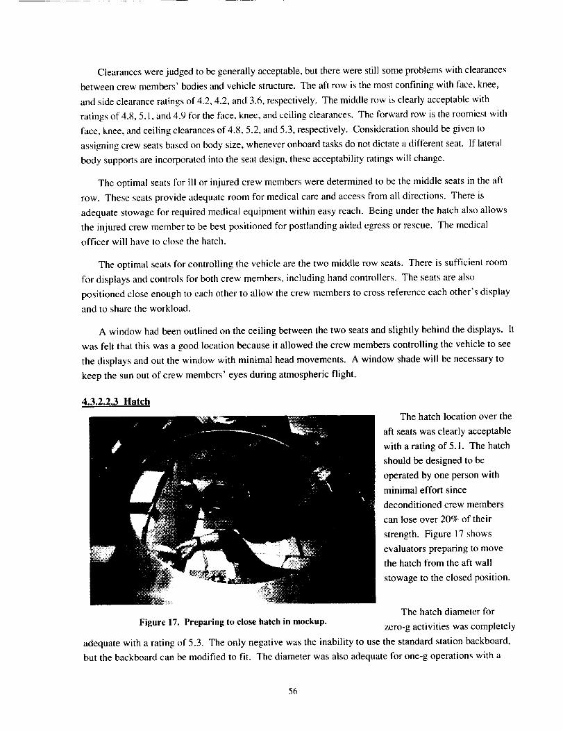
Clearanceswerejudgedtobegenerallyacceptable,buttherewerestill someproblemswithclearancesbetweencrewmembers'bodiesandvehiclestructure.Theaftrowis themostconfiningwithface,knee,andsideclearanceratingsof 4.2,4.2,and3.6,respectively.Themiddlerowisclearlyacceptablewithratingsof4.8,5.1,and4.9fortheface,knee,andceilingclearances.Theforwardrowistheroomiestwithface,knee,andceilingclearancesof4.8,5.2,and5.3,respectively.Considerationshouldbegiventoassigningcrewseatsbasedonbodysize,wheneveronboardtasksdonotdictateadifferentseat.If lateralbodysupportsareincorporatedintotheseatdesign,theseacceptabilityratingswill change.
Theoptimalseatsfor ill or injured crew members were determined to be the middle seats in the aft
row. These seats provide adequate room for medical care and access from all directions. There is
adequate stowage for required medical equipment within easy reach. Being under the hatch also allows
the injured crew member to be best positioned for postlanding aided egress or rescue. The medical
officer will have to close the hatch.
The optimal seats for controlling the vehicle are the two middle row seats. There is sufficient room
for displays and controls for both crew members, including hand controllers. The seats are also
positioned close enough to each other to allow the crew members to cross reference each other's display
and to share the workload.
A window had been outlined on the ceiling between the two seats and slightly behind the displays. It
was felt that this was a good location because it allowed the crew members controlling the vehicle to see
the displays and out the window with minimal head movements. A window shade will be necessary to
keep the sun out of crew members' eyes during atmospheric flight.
4.3.2.2.3 Hatch
The hatch location over the
aft seats was clearly acceptable
with a rating of 5.1. The hatch
should be designed to be
operated by one person with
minimal effort since
deconditioned crew members
can lose over 20% of their
strength. Figure 17 shows
evaluators preparing to move
the hatch from the aft wall
stowage to the closed position.
The hatch diameter for
Figure 17. Preparing to close hatch in mockup. zero-g activities was completely
adequate with a rating of 5.3. The only negative was the inability to use the standard station backboard,
but the backboard can be modified to fit. The diameter was also adequate for one-g operations with a
56
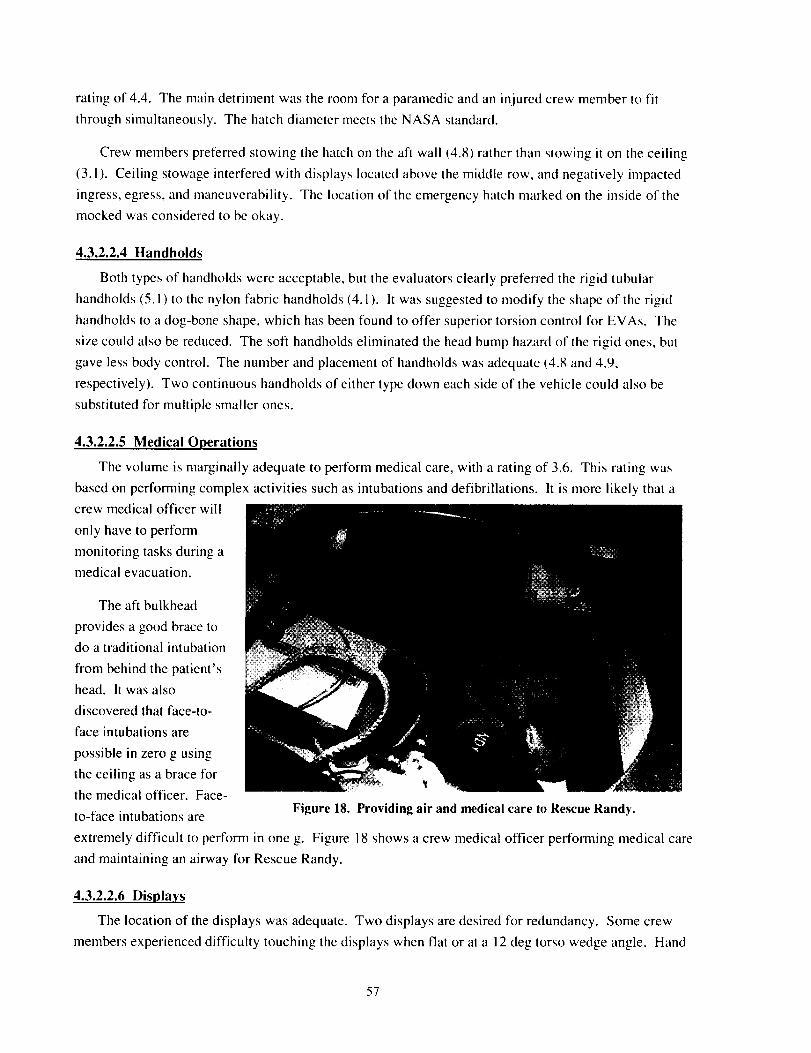
ratingof 4.4. Themaindetrimentwastheroomfor aparamedicandaninjuredcrewmemberto fitthroughsimultaneously.ThehatchdiametermeetstheNASAstandard.
Crewmemberspreferredstowingthehatchontheaftwall(4.8)ratherthanstowingit ontheceiling(3.1). Ceilingstowageinterferedwithdisplayslocatedabovethemiddlerow,andnegativelyimpactedingress,egress,andmaneuverability.Thelocationof theemergencyhatchmarkedontheinsideof themockedwasconsideredto beokay.
4.3.2.2.4 Handholds
Both types of handholds were acceptable, but the evaluators clearly preferred the rigid tubular
handholds (5.1) to the nylon fabric handholds (4.1). It was suggested to modify the shape of the rigid
handholds to a dog-bone shape, which has been found to offer superior torsion control for EVAs. The
size could also be reduced. The soft handholds eliminated the head bump hazard of the rigid ones, but
gave less body control. The number and placement of handholds was adequate (4.8 and 4.9,
respectively). Two continuous handholds of either type down each side of the vehicle could also be
substituted for multiple smaller ones.
4.3.2.2.5 Medical Operations
The volume is marginally adequate to perform medical care, with a rating of 3.6. This rating was
based on performing complex activities such as intubations and defibrillations. It is more likely that a
crew medical officer will
only have to perform
monitoring tasks during a
medical evacuation.
The aft bulkhead
provides a good brace to
do a traditional intubation
from behind the patient's
head. It was also
discovered that face-to-
face intubations are
possible in zero g using
the ceiling as a brace for
the medical officer. Face-
to-face intubations are Figure 18. Providing air and medical care to Rescue Randy.
extremely difficult to perform in one g. Figure 18 shows a crew medical officer performing medical care
and maintaining an airway for Rescue Randy.
4.3.2.2.6 Displays
The location of the displays was adequate. Two displays are desired for redundancy. Some crew
members experienced difficulty touching the displays when flat or at a 12 deg torso wedge angle. Hand
57
controls should be available so that crew members donl have to reach overhead to the displays during g-
loaded flight.
4.3.2.2.7 Crew Volume
Crew volume in the tested configuration was considered to be adequate for on-orbit station attached
operations, post-separation zero-g operations, and atmospheric flight and postlanding operations with
ratings of 4.7, 4.2, and 4.4, respectively. Access to stowed flight crew equipment and medical equipment
was also adequate (4.1 and 4, respectively). Evaluators did feel that the equipment stowed on the walls
and bulkheads should be minimized to prevent potential crew injury. Some stowed items were found to
interfere with crew members, but alternate stowage locations were found. Stowage needs to be
continually evaluated as designs are refined and new items are identified.
4.3.2.2.8 Helmets
Standard aircraft helmets were clearly adequate with a rating of 4.7. Custom helmets that are lower
profile and lighter weight would be better. The concept of head restraints was good. Headrests are not
necessary.
4.3.2.2.9 Constraints and Limitations
Seat design is still immature. More tests need to be conducted after the seats are designed. The
Soyuz-style seat was not rigid enough for adequate evaluation and had no knee restraints. Negative
opinions of the seat may change if these deficiencies are corrected for follow-on testing. Displays were
only foam mockups so final assessments of back angles could not be performed. Eye points need to be
defined and fixed, and then the displays and seats can be designed in concert to meet the eye point.
Consideration should be given to anthropometrics when defining the eye points. Vehicles typically use
adjustable seats and fixed displays to accommodate a population range. This may be more difficult to do
with supine seats.
4.4 Differences Between Phases
Phases 2 and 3 were essentially the same tests with small modifications to the seat layout and
stowage. The same performance data were collected during each phase. Slightly different
acceptability data were collected from the two phases as a result of the Delphi study. Data analysis
was conducted to compare the perforrriance between the two phases to determine if the mockup and
seat changes had a significant impact on the data. Table 19 shows the ANOVA E-values for the
performance variables from comparing Phase 2 to Phase 3. Variables that were significant at/2<0.05
appear in bold print.
A Duncan Multiple Range test of the performance data for the zero-g ingress of 3 healthy and 1 ill
crew member showed a significant difference (/2=0.04257). There was only one data point for this egress
type from Phase 3. The difference in the data could be explained after reviewing the videotapes for the
test. One evaluator became entangled in some unrelated support equipment near the mockup at the start
58
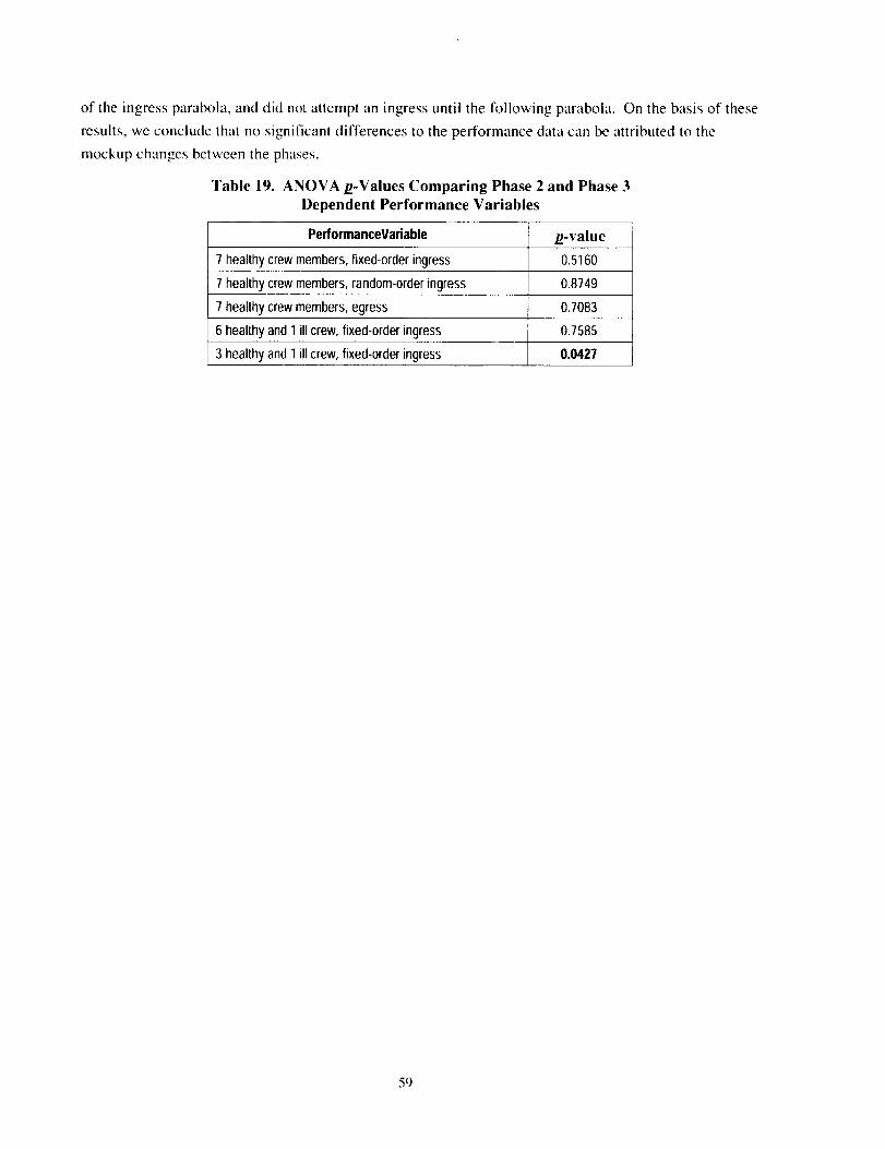
of the ingress parabola, and did not attempt an ingress until the following parabola. On the basis of these
results, we conclude that no significant differences to the performance data can be attributed to the
mockup changes between the phases.
Table 19. ANOVA p-Values Comparing Phase 2 and Phase 3
Dependent Performance Variables
PerfonnanceVariable /_-value
7 healthy crew members, fixed-order ingress 0.5160
7 healthy crew members, random-order ingress 0.8749
7 healthy crew members, egress 0.7083
6 healthy and 1 ill crew, fixed-order ingress 0.7585
3 healthy and 1 ill crew, fixed-order ingress 0.0427
59
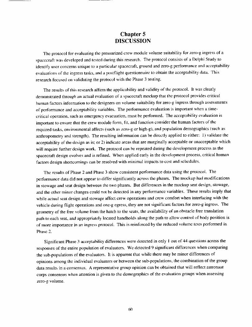
Chapter 5DISCUSSION
The protocol for evaluating the pressurized crew module volume suitability for zero-g ingress of a
spacecraft was developed and tested during this research. The protocol consists of a Delphi Study to
identify user concerns unique to a particular spacecraft, ground and zero-g performance and acceptability
evaluations of the ingress tasks, and a postflight questionnaire to obtain the acceptability data. This
research focused on validating the protocol with the Phase 3 testing.
The results of this research affirm the applicability and validity of the protocol. It was clearly
demonstrated through an actual evaluation of a spacecraft mockup that the protocol provides critical
human factors information to the designers on volume suitability for zero-g ingress through assessments
of performance and acceptability variables. The performance evaluation is important when a time-
critical operation, such as emergency evacuation, must be performed. The acceptability evaluation is
important to ensure that the crew module form, fit, and function consider the human factors of the
required tasks, environmental affects (such as zero-g or high-g), and population demographics (such as
anthropometry and strength). The resulting information can be directly applied to either: 1) validate the
acceptability of the design as is; or 2) indicate areas that are marginally acceptable or unacceptable which
will require further design work. The protocol can be repeated during the development process as the
spacecraft design evolves and is refined. When applied early in the development process, critical human
factors design shortcomings can be resolved with minimal impacts to cost and schedules.
The results of Phase 2 and Phase 3 show consistent performance data using the protocol. The
performance data did not appear to differ significantly across the phases. The mockup had modifications
in stowage and seat design between the two phases. But differences in the mockup seat design, stowage,
and the other minor changes could not be detected in any performance variables. These results imply that
while actual seat design and stowage affect crew operations and crew comfort when interfacing with the
vehicle during flight operations and one-g egress, they are not significant factors for zero-g ingress. The
geometry of the free volume from the hatch to the seats, the availability of an obstacle free translation
path to each seat, and appropriately located handholds along the path to allow control of body position is
of more importance in an ingress protocol. This is reinforced by the reduced volume tests performed in
Phase 2.
Significant Phase 3 acceptability differences were detected in only I out of 44 questions across the
responses of the entire population of evaluators. We detected 9 significant differences when comparing
the sub-populations of the evaluators. It is apparent that while there may be minor differences of
opinions among the individual evaluators or between the sub-populations, the combination of the group
data results in a consensus. A representative group opinion can be obtained that will reflect astronaut
corps consensus when attention is given to the demographics of the evaluation groups when assessing
zero-g volume.
60
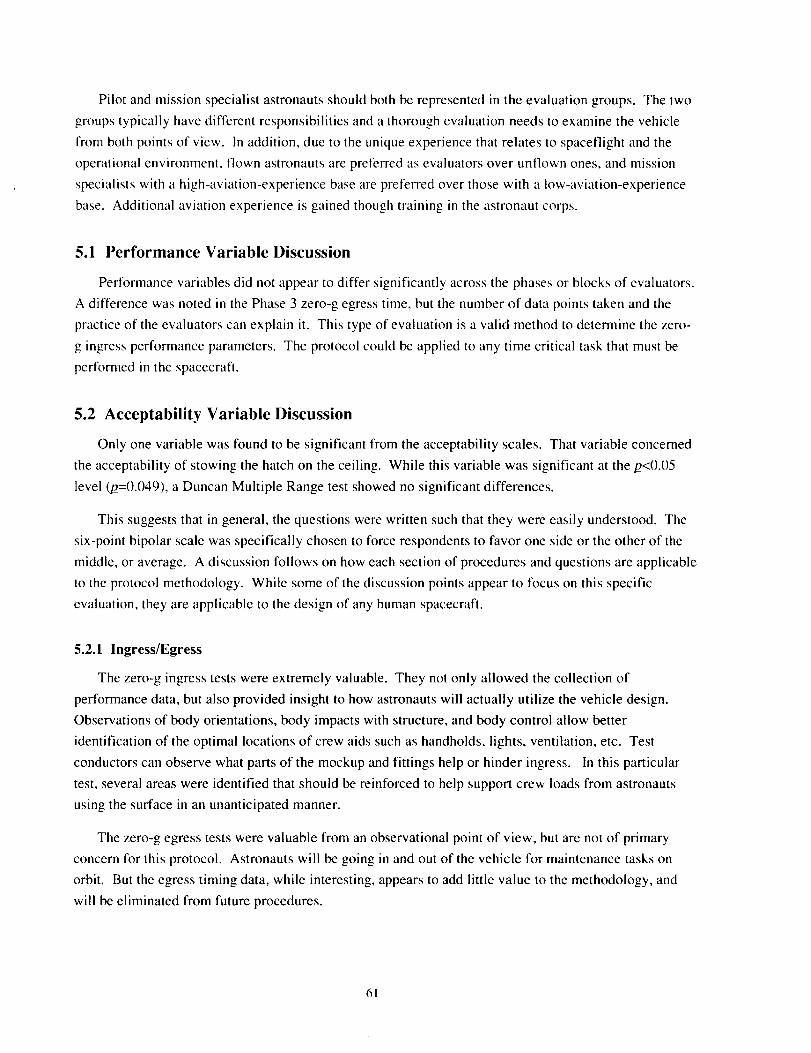
Pilotandmissionspecialistastronautsshouldbothberepresentedin theevaluationgroups.Thetwo
groups typically have different responsibilities and a thorough evaluation needs to examine the vehicle
from both points of view. In addition, due to the unique experience that relates to spaceflight and the
operational environment, flown astronauts are preferred as evaluators over unflown ones, and mission
specialists with a high-aviation-experience base are preferred over those with a low-aviation-experience
base. Additional aviation experience is gained though training in the astronaut corps.
5.1 Performance Variable Discussion
Performance variables did not appear to differ significantly across the phases or blocks of evaluators.
A difference was noted in the Phase 3 zero-g egress time, but the number of data points taken and the
practice of the evaluators can explain it. This type of evaluation is a valid method to determine the zero-
g ingress performance parameters. The protocol could be applied to any time critical task that must be
performed in the spacecraft.
5.2 Acceptability Variable Discussion
Only one variable was found to be significant from the acceptability scales. That variable concerned
the acceptability of stowing the hatch on the ceiling. While this variable was significant at the ,_<0.05
level (_=0.049), a Duncan Multiple Range test showed no significant differences.
This suggests that in general, the questions were written such that they were easily understood. The
six-point bipolar scale was specifically chosen to force respondents to favor one side or the other of the
middle, or average. A discussion follows on how each section of procedures and questions are applicable
to the protocol methodology. While some of the discussion points appear to focus on this specific
evaluation, they are applicable to the design of any human spacecraft.
5.2.1 Ingress/Egress
The zero-g ingress tests were extremely valuable. They not only allowed the collection of
performance data, but also provided insight to how astronauts will actually utilize the vehicle design.
Observations of body orientations, body impacts with structure, and body control allow better
identification of the optimal locations of crew aids such as handholds, lights, ventilation, etc. Test
conductors can observe what parts of the mockup and fittings help or hinder ingress. In this particular
test, several areas were identified that should be reinforced to help support crew loads from astronauts
using the surface in an unanticipated manner.
The zero-g egress tests were valuable from an observational point of view, but are not of primary
concern for this protocol. Astronauts will be going in and out of the vehicle for maintenance tasks on
orbit. But the egress timing data, while interesting, appears to add little value to the methodology, and
will be eliminated from future procedures.
61
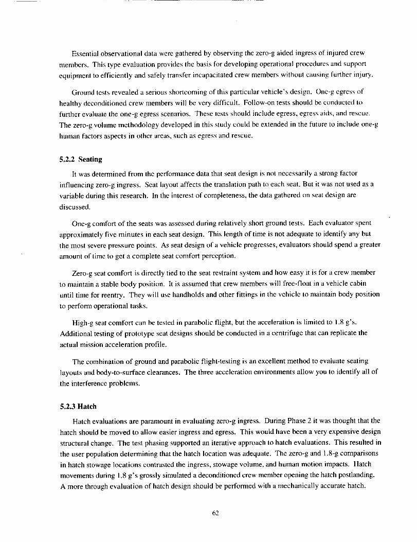
Essentialobservational data were gathered by observing the zero-g aided ingress of injured crew
members. This type evaluation provides the basis for developing operational procedures and support
equipment to efficiently and safely transfer incapacitated crew members without causing further injury.
Ground tests revealed a serious shortcoming of this particular vehicle's design. One-g egress of
healthy deconditioned crew members will be very difficult. Follow-on tests should be conducted to
further evaluate the one-g egress scenarios. These tests should include egress, egress aids, and rescue.
The zero-g volume methodology developed in this study could be extended in the future to include one-g
human factors aspects in other areas, such as egress and rescue.
5.2.2 Seating
It was determined from the performance data that seat design is not necessarily a strong factor
influencing zero-g ingress. Seat layout affects the translation path to each seat. But it was not used as a
variable during this research. In the interest of completeness, the data gathered on seat design are
discussed.
One-g comfort of the seats was assessed during relatively short ground tests. Each evaluator spent
approximately five minutes in each seat design. This length of time is not adequate to identify any but
the most severe pressure points. As seat design of a vehicle progresses, evaluators should spend a greater
amount of time to get a complete seat comfort perception.
Zero-g seat comfort is directly tied to the seat restraint system and how easy it is for a crew member
to maintain a stable body position. It is assumed that crew members will free-float in a vehicle cabin
until time for reentry. They will use handholds and other fittings in the vehicle to maintain body position
to perform operational tasks.
High-g seat comfort can be tested in parabolic flight, but the acceleration is limited to 1.8 g's.
Additional testing of prototype seat designs should be conducted in a centrifuge that can replicate the
actual mission acceleration profile.
The combination of ground and parabolic flight-testing is an excellent method to evaluate seating
layouts and body-to-surface clearances. The three acceleration environments allow you to identify all of
the interference problems.
5.2.3 Hatch
Hatch evaluations are paramount in evaluating zero-g ingress. During Phase 2 it was thought that the
hatch should be moved to allow easier ingress and egress. This would have been a very expensive design
structural change. The test phasing supported an iterative approach to hatch evaluations. This resulted in
the user population determining that the hatch location was adequate. The zero-g and 1.8-g comparisons
in hatch stowage locations contrasted the ingress, stowage volume, and human motion impacts. Hatch
movements during 1.8 g's grossly simulated a deconditioned crew member opening the hatch postlanding.
A more through evaluation of hatch design should be performed with a mechanically accurate hatch.
62
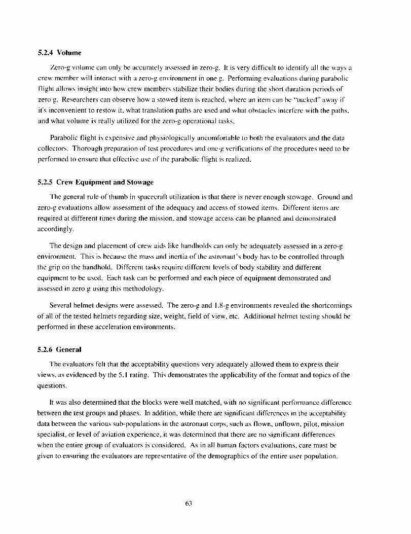
5.2.4 Volume
Zero-g volume can only be accurately assessed in zero-g. It is very difficult to identify all the ways a
crew member will interact with a zero-g environment in one g. Performing evaluations during parabolic
flight allows insight into how crew members stabilize their bodies during the short duration periods of
zero g. Researchers can observe how a stowed item is reached, where an item can be "tucked" away if
it's inconvenient to restow it, what translation paths are used and what obstacles interfere with the paths,
and what volume is really utilized for the zero-g operational tasks.
Parabolic flight is expensive and physiologically uncomfortable to both the evaluators and the data
collectors. Thorough preparation of test procedures and one-g verifications of the procedures need to be
performed to ensure that effective use of the parabolic flight is realized.
5.2.5 Crew Equipment and Stowage
The general rule of thumb in spacecraft utilization is that there is never enough stowage. Ground and
zero-g evaluations allow assessment of the adequacy and access of stowed items. Different items are
required at different times during the mission, and stowage access can be planned and demonstrated
accordingly.
The design and placement of crew aids like handholds can only be adequately assessed in a zero-g
environment. This is because the mass and inertia of the astronaut's body has to be controlled through
the grip on the handhold. Different tasks require different levels of body stability and different
equipment to be used. Each task can be performed and each piece of equipment demonstrated and
assessed in zero g using this methodology.
Several helmet designs were assessed. The zero-g and 1.8-g environments revealed the shortcomings
of all of the tested helmets regarding size, weight, field of view, etc. Additional helmet testing should be
performed in these acceleration environments.
5.2.6 General
The evaluators felt that the acceptability questions very adequately allowed them to express their
views, as evidenced by the 5. I rating. This demonstrates the applicability of the format and topics of the
questions.
It was also determined that the blocks were well matched, with no significant performance difference
between the test groups and phases. In addition, while there are significant differences in the acceptability
data between the various sub-populations in the astronaut corps, such as flown, unflown, pilot, mission
specialist, or level of aviation experience, it was determined that there are no significant differences
when the entire group of evaluators is considered. As in all human factors evaluations, care must be
given to ensuring the evaluators are representative of the demographics of the entire user population.
63
In addition, it was determined that the XCRV crew module as currently proposed meets the DRM
requirements for zero-g ingress and operations. Acceptability criteria were:
• Meeting the DRMs of the ISS Program as listed in SSP 50306 (ingress and hatch closure in less thanthree minutes).
• Meeting the NASA human factors and ergonomics standards as specified in NASA-STD-3000/T.
• Acceptable zero-g unaided ingress evaluations and volumetric assessments by the end users---members of the NASA Astronaut Office.
• Acceptable zero-g aided ingress and inflight medical monitoring evaluations by the NASA Flight
Medicine community.
64
Chapter 6
CONCLUSIONS AND FURTHER STUDY
6.1 Conclusions
This research was begun with the objective to develop a methodology for evaluation of crew volume
acceptability for zero-g ingress of spacecraft. The resulting methodology, the "Sanchez Protocol,"
consists of:
• A Delphi study that determined the evaluation factors most important to the end users.
• Procedures for the conduct of ground and inflight (zero-g and 1.8-g) evaluations of the crew volume.
• Postflight questionnaire using six-point bipolar scales to ascertain acceptability variable data.
• Data analysis techniques to assess performance and acceptability data.
The results of this research validate the protocol. The blocks were well matched, with no significant
performance difference between the test groups and phases. In addition, while there are significant
differences in the acceptability data between the various sub-populations in the astronaut corps, such as
flown, unflown, pilot, mission specialist, or level of aviation experience, it was determined that there are
no significant differences when the entire group of evaluators is considered. As in all human factors
evaluations, care must be given to ensuring the evaluators are representative of the demographics of the
entire user population.
While this protocol was specifically designed to evaluate the zero-g ingress task, it is applicable to
the human factors evaluation of any zero-g task performed in a spacecraft. The basic protocol is far
reaching, and the only modifications required to expand it would be to refocus the Delphi questions and
to modify the procedural steps and postflight questions to focus on the new task.
The development of the protocol expands the state of the art of human factors evaluations in zero g.
No standard evaluation methodology has been previously used. The Sanchez Protocol is proposed as the
new standard for any future human factors evaluations of zero-g tasks in spacecraft that are performed by
the government, industry, or foreign space agencies.
6.2 Further Study
This protocol specifically focuses on zero-g ingress. During evaluation of the protocol, several other
areas and questions were identified that require further research. The methodology could be expanded to
other human factors related areas of spacecraft assessment including one-g egress and rescue, displays,
maintenance tasks, and other operational tasks.
65
REFERENCES
Akimoto, T., lto, T., Yamamoto, M., Bando, T., and lnoue, Y. (1994) Orbital Reentry Experiment
(OREX) - First Step of Space Return Flight Demonstrations in Japan. Proceedings of the 45 m
Congress of the International Astronautical Federation, IAF Paper No. 94-V.2.525. Jerusalem,
Israel: American Institute of Aeronautics and Astronautics.
Baccini H., Charles, J., Colrat, J., Georges, J. F., Marcoux, J., and Herholz, J. (1986-1987) Hermes
Safety and Rescue. Space Safety and Rescue, Vol. 70, IAA Paper No. 87-577, 291-303.
Barnett. (1970) Conceptual Design Analysis and Technology Assessment of Space Escape Systems,
Volume 1 - Summary. North American Rockwell Corporation.
Bolger, P. H. (1970) Evolution of Escape Systems for Manned Space Flight. Third International Space
Rescue Symposium, International Academy of Astronautics, 1i 5-164.
Bradley, R. H., and Carter, W. K. (1969) Low-Earth-Orbit Emergency-Escape Vehicle. Second
International Space Rescue Symposium, International Academy of Astronautic, 246-270.
Brinkley, J. W., Specker, L. J., and Mosher, S. E. (1989) Development of Acceleration Exposure Limits
for Advanced Escape Systems. Implications of Advanced Technologies for Air and Spacecraft
Escape, Advisory Group for Aerospace Research and Development, Conference Proceedings,
No. 472. AGARD NATO. !-1 - 1-14.
Brooks, C. G., Grimwood, J. M., and Swenson, L. S. (1979) Chariots for Apollo: A History of Manned
Lunar Spacecraft. NASA SP-4205. Houston, TX: National Aeronautics and Space
Administration.
Burrough, B. (1998) Dragonfly. Harper Collins.
Bush, L. B., Robinson, J. C., and Wahls, D. M. (1993) Preliminary Structural Evaluation and Design of
the HL-20. Journal of Spacecraft and Rockets, Vol. 30, No. 5,567-572.
Cerimele, C. J. (1999) X-38 Human Tolerance Design Analysis. (Presentation) Lyndon B. Johnson
Space Center. Houston, TX.
Cmiral, J., Dolezel, V., Dvorak, J., Pipal, M., and Sulc, J. (197 ! ) Possibilities and Dangers During Long
Working Periods in Space. Fourth International Space Rescue Symposium, International
Academy of Astronautics, 273-279.
66
Cochran,W.G., (1983)Planning and Analysis of Observational Studies. New York: John Wiley and
Sons.
Compton, W. D. (I 989) Where No Man Has Gone Before: A History of Apollo Lunar Exploration
Missions. NASA SP-4214. Houston, TX: National Aeronautics and Space Administration.
Dalkey, N. (1967) _. Santa Monica: The RAND Corporation.
Daniher C. E., and Cureton, K. L. (1992) A Lifeboat for Space Station: The Assured Crew Return
Vehicle (ACRV). Space Safety and Rescue, Vol. 84, IAA Paper No. 92-389 141-155.
Department of Defense. (1992) MIL-STD-1472: Human Engineering Design Criteria for Military
Systems, Equipment, and Facilities. Washington, DC: Department of Defense.
Ehrlich, C. F. (1993) HL-20 Concept: Design Rationale and Approach. Journal of Spacecraft and
Rockets, Vol. 30, No. 5,573-581.
Fabian, J. (1988-1989) An Historical Perspective on Crew Rescue and the Role of the Association of
Space Explorers. Space Safety and Rescue, Vol. 77, IAA Paper No. 89-618, 227-238.
Fieisig, R., and Bolger, P. FI. ( 1971 ) Survey of Space Flight Safety Systems. Fourth International Space
Rescue Symposium, International Academy of Astronautics, 23-66.
Fleisig, R., and Heath, G. W. (1968) Survey of Space Rescue Capabilities. First International Space
Rescue Symposium, International Academy of Astronautics, 42-65.
Francis, R. H. (1969) Rescue From Earth Orbit. Second International Space Rescue Symposium,
International Academy of Astronautics 197-212.
Frisch, G. D. (1978) A Human Body and Crew Station Modeling System for Motion Studies. Advisory
Group for Aerospace Research & Development (AGARD) Conf. Proceedings No. 253, Models
and Analogues for the Evaluation of Human Biodynamic Response, Performance, and Protection,
A21-1-13.
Furniss, T. (1986) Manned Spaceflight Log. London: Jane's.
Grimard, M., and Debas, G. (1988) Missions and System Requirements for an Escape Vehicle Within a
European Manned Space Infrastructure. Space Safety and Rescue, Vol. 77, IAA Paper No. 88-
514, 27-49.
67
Grimard,M.,andDebas,G. (1993)EuropeanACRV:A Solutionfor SpaceStationCrewAssured
Return.Space Safety and Rescue, Vol. 87, IAA Paper No. IAA.6.1-93-733, 57-68.
Hacker, B. C., and Alexander, C. C. (1977) On the Shoulders of Titans: A History of Project Gemini.
NASA SP-4203. Houston, TX: National Aeronautics and Space Administration.
Heath, G. W. (1971) Survey of Recovery Capabilities. Fourth International Space Rescue Symposium,
International Academy of Astronautics, 117-142.
Helmer, O. (1983) Looking Forward: A Guide to Futures Research. Beverly Hills: Sage Publications.
Hicks, C.R. (1982) Fundamental Concepts in the Design of Experiments (3 rd Ed.). Fort Worth:
Saunders College Publishing.
Housten, S. (1993) Implementation of the Soyuz ACRV for the Space Station Freedom. Space Safety
and Rescue, Vol. 87, IAA Paper No. IAA.6.1-93-732, 41-55.
Housten, S., Eisner, T., Redler, K., Svendsen, H., and Wenzel, S. (1992) Space Rescue System
Definition (System Performance Analysis and Trades). Space Safety and Rescue, Vol. 84, IAA
Paper No. 92-388, 123-139.
Johnson, D. and King, M. (1988) BASIC forecasting techniques. London: Butterworths.
Johnston, S. L. (1997) Medical Operations Current Positions, Issues, and Recommendations for the
Development of the International Space Station Medical Mission Assured Crew Return Vehicle.
(Correspondence) Houston, TX: National Aeronautics and Space Administration.
Johnston, S. L., Jones, J. A., Ross, C. E., Cerimele, C. J., and Fox, J. L. (I 999) NASA International
Space Station (ISS) Crew Return Vehicle (CRV) Seat and Cockpit Configuration and Design
Challenges [research documentation].
Kane, F. X. (1984-1985) A Thirty-Year Perspective on Manned Space Safety and Rescue: Where
We've Been; Where We Are; Where We Are Going. Space Safety and Rescue, Vol. 64, IAA
Paper No. 84-270, 61-88.
Kelly, B. ( 1991 ) A Systems Analysis of Emergency Escape and Recovery Systems for the U.S. Space
Station. Thesis AFIT/GSO/AA/86D-5. U.S. Air Force.
Kerlinger, F. N. (1973) Foundations of Behavioral Research (2 °d Ed.). New York: Holt, Rinehart and
Winston.
68
Linstone,H.andTuroff,M. (1975)The delphi method. Reading, MA: Addison-Wesley Publishing Co.
Lloyd, J., Eymar, P., Housten, S., and Grimard, M. (1991) Space Rescue System Analysis and Design.
Space Safety and Rescue, Vol. 82, IAA Paper No. 91-58 I, 17-30.
Lucid, S. (1998) Six Months on Mir, Scientific American, May 1998, 46-55.
Manley, M. E. (1998a) Human Research Protocol: Crew Return Vehicle and Crew Transfer Vehicle
(CTV) Crew Cabin Accommodation Study. Downey, CA: Boeing North American, Inc. and
Alenia Aerospazio.
Manley, M. E. (1998b) Test Plan for the KC- 135 Zero-g Test Series of the Boeing CRV Ingress Tests
and Aienia CTV Donning/Doffing/Ingress Tests. Downey, CA: Boeing North American, Inc.
and Alenia Aerospazio.
Manley, M. E., Basile, L., and Sanchez, M. J. (1998) Crew Return Vehicle (CRV) and (CTV)
Accommodations Study. International Astronautical Federation Proceedings. IAF/IAA-98-G-
3.01: in press.
Meister, D., and Rabideau, G. F. (1965) Human Factors Evaluation in Systems Development. New
York: John Wiley and Sons.
Montgomery, D.C. (1991) Design and Analysis of Experiments (3 r_ Ed.). New York: John Wiley &
Sons.
Moskwa, P. (1996) 90 Days Study Final Meeting. Toulouse, France: Centre spatial de Toulouse -
Infrastructure Orbital.
Mott, D. R. (1974) Passenger Escape From Commercial Aircraft. International Air Safety Seminar
Proceedings, 241-247. Williamsburg, VA: Flight Safety Foundation Inc.
Naftel J. C. and Talay T. A. (1993) Ascent Abort Capability for the HL-20. Journal of Spacecraft and
Rockets, Vol. 30, No. 5,628-634.
National Aeronautics and Space Administration (1987). Man-Systems Integration Standards, Vol. I1.
NASA-STD-3000. Lyndon B. Johnson Space Center, Houston, TX.
National Aeronautics and Space Administration (1989) Man-Systems Integration Standards, Vol. I.
NASA-STD-3000. Lyndon B. Johnson Space Center, Houston, TX.
69
NationalAeronauticsandSpaceAdministration(1992)HL-20 Model for Personnel Launch System
Research. NASA Facts Press Release, No. NFI72. Langley Research Center, Langley, VA.
National Aeronautics and Space Administration, Johnson Space Center (1994) Man-Systems Integration
Standards, Vol. II1. NASA-STD-3000. Lyndon B. Johnson Space Center, Houston, TX.
National Aeronautics and Space Administration (1995) International Space Station Flight Crew
Integration Standard. NASA-STD-3000/T (SSP 50005, Rev. B). Lyndon B. Johnson Space
Center, Houston, TX.
National Aeronautics and Space Administration (I 997) System Specification for the International Space
Station, Rev E. SSP 41000. Lyndon B. Johnson Space Center, Houston, TX.
National Aeronautics and Space Administration (1998) International Space Station (ISS) - Crew Return
Vehicle (CRV) Interface Requirements Document. SSP-50410. Lyndon B. Johnson Space
Center, Houston, TX.
National Aeronautics and Space Administration (1999) International Space Station (ISS) - Crew Return
Vehicle (CRV) Performance Requirements, SSP 50306, Revision A. Lyndon B. Johnson Space
Center, Houston, TX.
National Aeronautics and Space Administration (1999) Crew Return Vehicle Requirements Document.
JSC-28351, Revision B. Lyndon B. Johnson Space Center, Houston, TX. [for information
contact the JSC Advanced Development Office]
Nguyen, H. P., and Frank, F. (1988) Hermes Crew Escape Module. Space Safety and Rescue, Vol. 77,
IAA Paper No. 88-060, 73-84.
Nguyen, H. P., Rolfo, A., and Charles, J. (1988) Hermes Crew Escape Module Configuration Studies.
Space Safety and Rescue, Vol. 77, IAA Paper No. 89-616, 217-226.
Oberg, J. (198 I) Red Star in Orbit. New York: Random House.
Oberg, J. (1999) Secrets of Soyuz. LaunchSpace Magazine, March/April 1999, 52-54.
Peterson, W. (1996) Crew Position Update. X-CRV Note of Interest - Systems Engineering Team
(NOISE) #6. Houston, TX: National Aeronautics and Space Administration.
Philip, C. (1988) The Soviet Manned Space Program. London: Salamander Books.
70
Puls,J. andWalbrodt,A. (1990) DesignAspectsof aRescueSystemfor MannedSpaceflight.Space
Safety and Rescue, Voi. 79, IAA Paper No. 90-560, 63-70.
Roe, R. W. (1993) Occupant Packaging. In J. B. Peacock and W. Karwowski (Eds.), Automotive
ergonomics - Human factors in the design and use of automobiles. London: Taylor & Francis.
Roebuck, J. A. (1993) Anthropometric Methods: Designing to Fit the Human Body. Santa Monica:
Human Factors and Ergonomics Society.
Roebuck, J. A., Kroemer+ K. H. E., and Thomson, W. G. (1975) Engineering Anthropometr¥ Methods.
New York: Wiley-Interscience.
Sage, A. P. (1977) Methodology for Large-Scale Systems. New York: McGraw-Hill.
Salvendy, G., ed. (1992) Handbook of Industrial Engineering, Second Edition. New York: Wiley
Interscience.
Sanchez, M. J. (1996a) Experimental Crew Return Vehicle (X-CRV) Project Crew Module Mockup
KC-135 Flight Test Evaluation: Test Equipment Data Package. Houston, TX: National
Aeronautics and Space Administration.
Sanchez, M. J. (1996b) X-CRV Project 4 Person Crew Module Mockup KC-135 Flight Test Plan.
Houston, TX: National Aeronautics and Space Administration.
Sanchez, M. J. (1996C) X-CRV Crew Module Evaluation #1. Houston, TX: National Aeronautics and
Space Administration.
Sanchez, M. J. (1997) Crew Evaluations of Experimental Crew Return Vehicle (X-CRV) Mockup
Onboard the KC-135. (memo no. EX12-97-48) Houston, TX: National Aeronautics and Space
Administration.
Sanchez, M. J. (1998a) X-38 Crew Module Mockup KC-135 Flight Test Evaluation: Flight Test Plan.
Houston, TX: National Aeronautics and Space Administration, Houston.
Sanchez, M. J. (1998b) X-38 Crew Module Mockup KC-135 Flight Test Evaluation: Test Equipment
Data Package. Houston, TX: National Aeronautics and Space Administration.
Sanchez, M. J. (1999a) X-38 Crew Module Mockup KC-135 Flight Test Evaluation: Test Equipment
Data Package, 3 _dSeries Houston, TX. National Aeronautics and Space Administration
71
Sanchez,M.J.(1999b)X-38 Crew Module Mockup KC-135 Flight Test Evaluation: Flight Test Plan,
3r° Series. Houston, TX. National Aeronautics and Space Administration
Severin, G. I. ( 1991 ) Crew Escape Subsystems for Space Transportation Subsystems. Space Safety and
Rescue, Vol. 82, IAA Paper No. 91-585, 77-88.
Shirouzu, M., Takashi, K., Akimoto, T., Watanabe, S., Shimoda, T. (1994) HYFLEX Project for the
Development of HOPE. Proceedings of the 19 'h International Symposium on Space Technology
and Science. Paper No. ISTS 94-g-12. Yokohama, Japan.
Society of Automotive Engineers. (1990) 1990 SAE handbook, Volume 4, on highway vehicles and off
road highway machinery. Warrendale, PA: SAE.
Stevenson, L. D. (1994) Soyuz Anthropometric Limitations for Crew members. (Presentation)
Houston, TX: National Aeronautics and Space Administration.
Stone, H. W. and MacConochie, I. O. (1993) HL-20 Subsystem Design. Journal of Spacecraft and
Rockets, Vol. 30, No. 5,590-596.
Stone, H. W. and Piland, W. M. (1993) 21st Century Space Transportation System Design Approach:
HL-20 Personnel Launch System. Journal of Spacecraft and Rockets, Voi. 30, No. 5, 521-528.
Sweigert, R. L. and Schabacker, W. H. (1974) The delphi technique: How well does it work in setting
educational goals? Paper presented at the Annual Meeting of the American Educational
Research Association. Chicago, IL: ERIC Document Reproduction Service No. ED 091 415.
Swenson, L. S., Grimwood, J. M., and Alexander, C. C. (1966) This New Ocean: A History of Project
Mercury. NASA SP-4201. Houston, TX: National Aeronautics and Space Administration.
Taylor, J. K. (1990) Statistical Techniques for Data Analysis. Boca Rotan: Lewis Publishers, Inc.
Tedeman, L. G. and Wright, K. (1992) International Spaceflight Crew Rescue Standards. Space Safety
and Rescue, Vol. 84, IAA Paper No. 92-390, 157-164.
Thangavelu, M. (1990) An Airlock-Based Architecture for Space Station Freedom Assured Crew
Return Capability. Space Safety and Rescue, Vol. 79, IAA Paper No. 90-561, 71-75.
Turnhill, R. (1978) The Observer's Spaceflight Directory. London: Frederick _ are.
72
Urie,D.M.,Floreck,P.A., McMorris,J.A.,andElvin,J.D. (1993)DesignforEffectiveDevelopment
andPrototypingof the HL-20. Journal of Spacecraft and Rockets, Vol. 30, No. 5,582-589.
Virzi, R. A. (1992) Refining the test phase of usability evaluation: How many subjects is enough?
Human Factors, 34,457-468.
Webler, T., Levine, D., Rakel, H., and Renn, O. (1991) A Novel Approach to Reducing Uncertainty:
The Group Delphi. Technological Forecasting and Social Change, Vol. 39, 253-263.
Weimer, J. (1995) Research Techniques in Human Engineering. Englewood Cliffs: Prentice Hall.
Wiener, E. L., and Nagel, D. C., eds. (1988) Human Factors in Aviation. San Diego: Academic Press,
Inc.
Wild, J. W. and Perchonok, E. (1968) Low Earth Orbit Escape and Rescue Concepts. First International
Space Rescue Symposium, International Academy of Astronautics, 79-100.
Wild, J. W. and Schaefer, H. (1970) Space Rescue Operations. Third International Space Rescue
Symposium, International Academy of Astronautics 166-192.
Willshire, K. F., Simonsen, L. C., and Wiilshire, W. L. (1993) Human Factors Evaluation of the HL-20
Full-Scale Model. Journal of Spacecraft and Rockets, Vol. 30, No. 5,606-614.
Woodson, W. E., Tillman, B., and Tillman, P., eds. (1992) Human Factors Design Handbook, Second
Edition. New York: McGraw-Hill.
Woudenberg, F. (1991) An Evaluation of Delphi. Technological Forecasting and Social Change,
Vol. 40, 131 - 150.
73

74
APPENDIX 1
7-Person KC-135 Flight Test Procedure
75
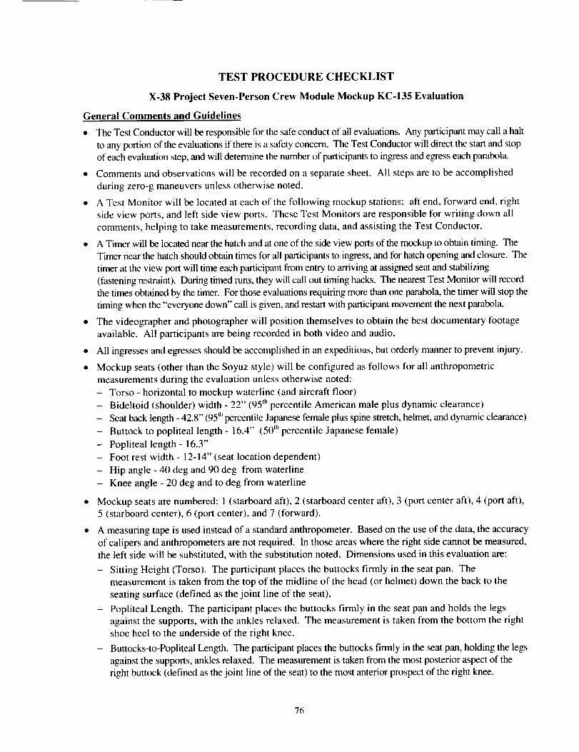
TEST PROCEDURE CHECKLIST
X-38 Project Seven-Person Crew Module Mockup KC-135 Evaluation
General Comments and Guidelines
• The Test Conductor will be responsible for the safe conduct of all evaluations. Any participant may call a halt
to any portion of the evaluations if there is a safety concern. The Test Conductor will direct the start and stop
of each evaluation step, and will determine the number of participants to ingress and egress each parabola.
• Comments and observations will be recorded on a separate sheet. All steps are to be accomplished
during zero-g maneuvers unless otherwise noted.
• A Test Monitor will be located at each of the following mockup stations: aft end, forward end, right
side view ports, and left side view ports. These Test Monitors are responsible for writing down all
comments, helping to take measurements, recording data, and assisting the Test Conductor.
• A Timer will be located near the hatch and at one of the side view ports of the mockup to obtain timing. The
Timer near the hatch should obtain times for all participants to ingress, and for hatch opening and closure. The
timer at the view port will time each participant from entry to arriving at assigned seat and stabilizing
(fastening restraint). During timed runs, they will call out timing hacks. The nearest Test Monitor will record
the times obtained by the timer. For those evaluations requiring more than one parabola, the timer will stop the
timing when the "everyone down" call is given, and restart with participant movement the next parabola.
• The videographer and photographer will position themselves to obtain the best documentary footage
available. All participants are being recorded in both video and audio.
• All ingresses and egresses should be accomplished in an expeditious, but orderly manner to prevent injury.
• Mockup seats (other than the Soyuz style) will be configured as follows for all anthropometric
measurements during the evaluation unless otherwise noted:
- Torso - horizontal to mockup waterline (and aircraft floor)
- Bideltoid (shoulder) width - 22" (95 th percentile American male plus dynamic clearance)
- Seat back length - 42.8" (95 d'percentile Japanese female plus spine stretch, helmet, and dynamic clearance)
- Buttock to popliteal length - 16.4" (50 'h percentile Japanese female)
- Popliteal length - 16.3"
- Foot rest width - 12-14" (seat location dependent)
- Hip angle - 40 deg and 90 deg from waterline
- Knee angle - 20 deg and to deg from waterline
• Mockup seats are numbered: 1 (starboard aft), 2 (starboard center aft), 3 (port center aft), 4 (port aft),
5 (starboard center), 6 (port center), and 7 (forward).
• A measuring tape is used instead of a standard anthropometer. Based on the use of the data, the accuracy
of calipers and anthropometers are not required. In those areas where the right side cannot be measured,the left side will be substituted, with the substitution noted. Dimensions used in this evaluation are:
- Sitting Height (Torso). The participant places the buttocks firmly in the seat pan. Themeasurement is taken from the top of the midline of the head (or helmet) down the back to the
seating surface (defined as the joint line of the seat).
- Popliteal Length. The participant places the buttocks firmly in the seat pan and holds the legs
against the supports, with the ankles relaxed. The measurement is taken from the bottom the right
shoe heel to the underside of the right knee.
- Buttocks-to-Popliteal Length. The participant places the buttocks firmly in the seat pan, holding the legs
against the supports, ankles relaxed. The measurement is taken from the most posterior aspect of theright buttock (defined as the joint line of the seat) to the most anterior prospect of the right knee.
76

Parabola Overview
Number ofParabola Set/Task
Parabolas
Parabola Set #1
Orientation
Practice IngressPractice EgressPause
Timed Ingress (healthy, fixed order)
Close Hatch, Strap In, Volume Assessments
Open Hatch, Egress
I
22
1
2
4
0-egress in 1 g
Total
Parabola Set #2
Timed Ingress (healthy, random order)Close Hatch, Strap In, Volume Assessments
Open Hatch, Egress
Total
Parabola Set #3
Timed Ingress (7 crew, 1 injured, fixed order)Close Hatch, Strap In,
Open Hatch, Egress
Timed Ingress (7 crew, 2 injured, fixed order)
Close Hatch, Strap In,
Open Hatch, Egress
Total
Parabola Set #4
Timed Ingress (4-7 crew, 1 injured, fixed order)
Close Hatch, Strap In,Medical Evaluations
Open Hatch, Egress
Total
Parabola Set #5
Timed Ingress (healthy, random order)
Close Hatch, Strap In, volume assessmentsOpen Hatch, egress
Timed Ingress (healthy, fixed order)
Close Hatch, Strap In, Volume Assessments
Open Hatch, Egress
12
3
I
2
3
1
2
12
2
1
10I
14
Total 12
Total Number of Parabolas 60
77
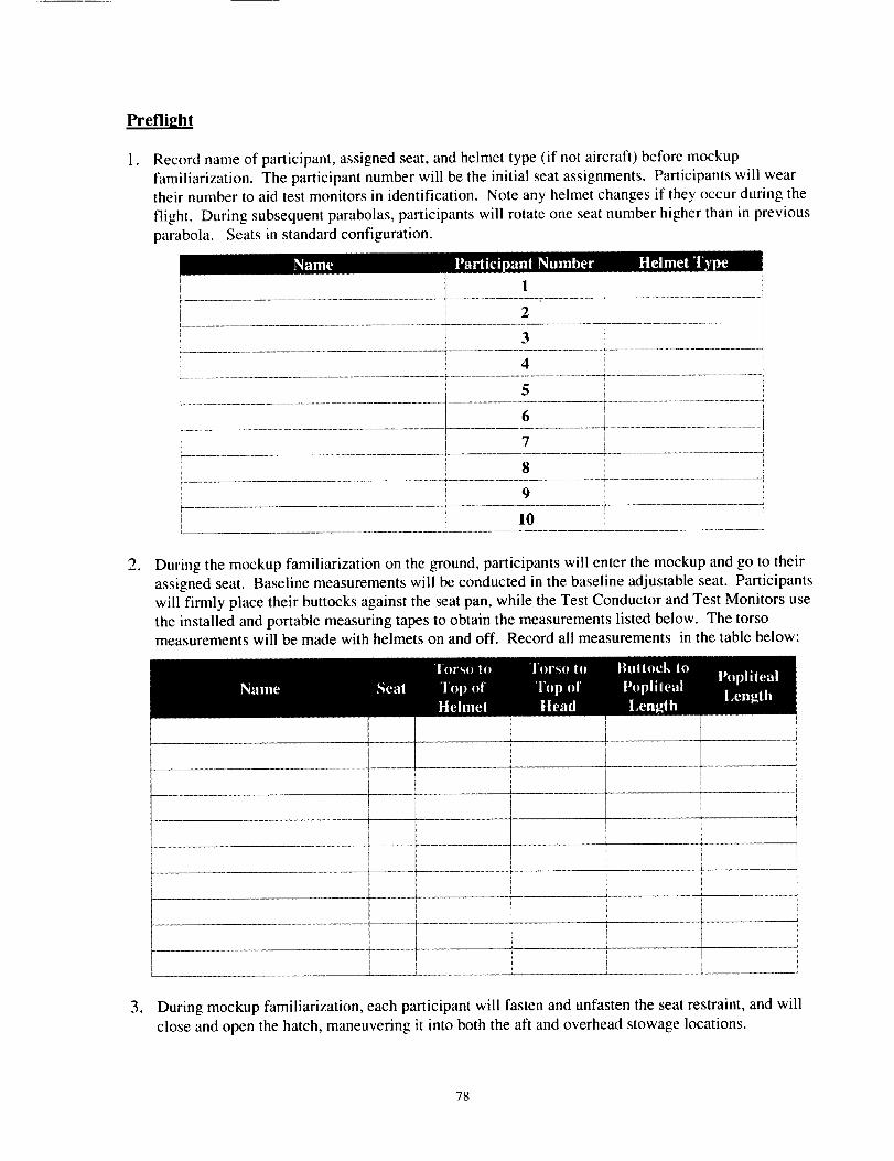
Preflight
I. Record name of participant, assigned seat, and helmet type (if not aircraft) before mockup
familiarization. The participant number will be the initial seat assignments. Participants will weartheir number to aid test monitors in identification. Note any helmet changes if they occur during the
flight. During subsequent parabolas, participants will rotate one seat number higher than in previous
parabola. Seats in standard configuration.
Name Participant Number Helmet Type
.
! 1
2Ii............................................................................................................................................................................................................................................ 1
3
4
5
6
' 7r
.............................................................................................................. _ ............................................. $....................................................................
8
9 i........................................................................... i ......................... _ .............................................., 10
[ ........................................................................ 1.......................................................
During the mockup familiarization on the ground, participants will enter the mockup and go to their
assigned seat. Baseline measurements will be conducted in the baseline adjustable seat. Participantswill firmly place their buttocks against the seat pan, while the Test Conductor and Test Monitors use
the installed and portable measuring tapes to obtain the measurements listed below. The torsomeasurements will be made with helmets on and off. Record all measurements in the table below:
. During mockup familiarization, each participant will fasten and unfasten the seat restraint, and will
close and open the hatch, maneuvering it into both the aft and overhead stowage locations.
78
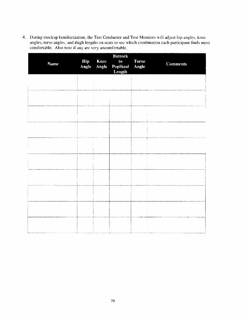
. During mockup familiarization, the Test Conductor and Test Monitors will adjust hip angles, knee
angles, torso angles, and thigh lengths on seats to see which combination each participant finds most
comfortable. Also note if any are very uncomfortable.
Buttock
Name Hip Knee to Torso CommentsAngle Angle Popliteal Angle
Length
79
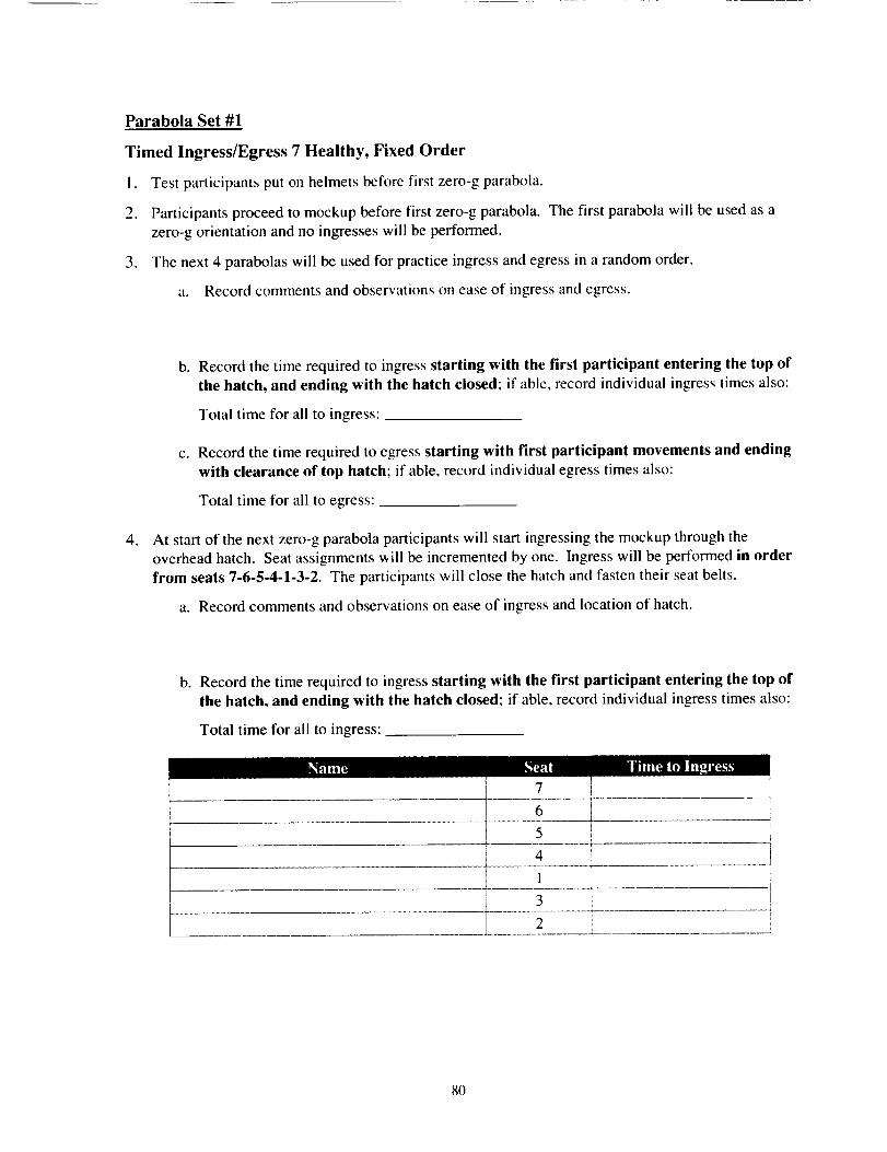
Parabola Set #1
Timed Ingress/Egress 7 Healthy, Fixed Order
I. Test participants put on helmets before first zero-g parabola.
2. Participants proceed to mockup before first zero-g parabola. The first parabola will be used as a
zero-g orientation and no ingresses will be performed.
3. The next 4 parabolas will be used for practice ingress and egress in a random order.
a. Record comments and observations on ease of ingress and egress.
.
b. Record the time required to ingress starting with the first participant entering the top of
the hatch, and ending with the hatch closed; if able, record individual ingress times also:
Total time for all to ingress:
c. Record the time required to egress starting with first participant movements and ending
with clearance of top hatch; if able, record individual egress times also:
Total time for all to egress:
At start of the next zero-g parabola participants will start ingressing the mockup through the
overhead hatch. Seat assignments will be incremented by one. Ingress will be performed in order
from seats 7-6-5-4-1-3-2. The participants will close the hatch and fasten their seat belts.
a. Record comments and observations on ease of ingress and location of hatch.
b. Record the time required to ingress starting with the first participant entering the top of
the hatch, and ending with the hatch closed; if able, record individual ingress times also:
Total time for all to ingress:
Name Seat Time to Ingress
T v• i
i 6
i 5 •.......... --.+ _.
4 !
! 1 +-[
3
2
8O
Hatch, Volume, Handhold, and Stowage Evaluations
5. During parabola, participant in seat 2 will reposition hatch from the hatch hole to the aft wall andback to the hatch hole. Record comments and observations.
6. During parabola, participant in seat 2 will reposition hatch from the hatch hole to the ceiling. Recordcomments and observations.
7. During, parabola, participant in seat 3 will reposition hatch from the ceiling to the hatch hole.Record comments and observations.
8. During parabola, participant in seat 3 will reposition hatch from the hatch hole to the aft wall andback to the hatch hole. Record comments and observations.
9. During parabolas and high-g maneuvering, all participants will evaluate handhold design number andlocation. Record comments and observations.
10. During parabolas, participants will assess acceptability of available volume in crew module for zero
g. Anticipated zero-g operations will include monthly systems checkout, removing seats to access
LRUs, transporting and monitoring ill/injured crew members from station to Earth, emergency
evacuation of healthy crew members from damaged station, and some TBD crew interfaces with
vehicle during return to Earth (TBD system monitoring and management, etc.) Consideration should
be given to the fact that there will be additional equipment not shown during this flight that will needto be stowed. Record comments and observations.
1 1. During high-g maneuvers, participants will assess acceptability of available volume in crew module
for reentry and atmospheric flight. Anticipated g-loaded operations will include monitoring
ill/injured crew members during flight, and some TBD crew interfaces with vehicle during return to
Earth (TBD system monitoring and management, backup parachute controls, parafoil guidance, etc.)
Consideration should be given to the fact that there will be additional equipment not shown duringthis flight that will need to be stowed. Record comments and observations.
81
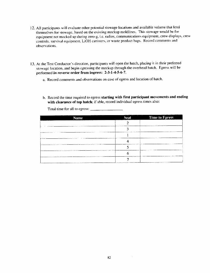
12. All participants will evaluate other potential stowage locations and available volume that lendthemselves for stowage, based on the existing mockup moldlines. This stowage would be for
equipment not mocked up during zero-g, i.e. radios, communications equipment, crew displays, crewcontrols, survival equipment, LiOH canisters, or waste product bags. Record comments andobservations.
13. At the Test Conductor's direction, participants will open the hatch, placing it in their preferred
stowage location, and begin egressing the mockup through the overhead hatch. Egress will be
performed in reverse order from ingress: 2-3.1-4-5-6-7.
a. Record comments and observations on ease of egress and location of hatch.
b° Record the time required to egress starting with first participant movements and ending
with clearance of top hatch; if able, record individual egress times also:
Total time for all to egress:
Name
1
4
5
6
7 !
82
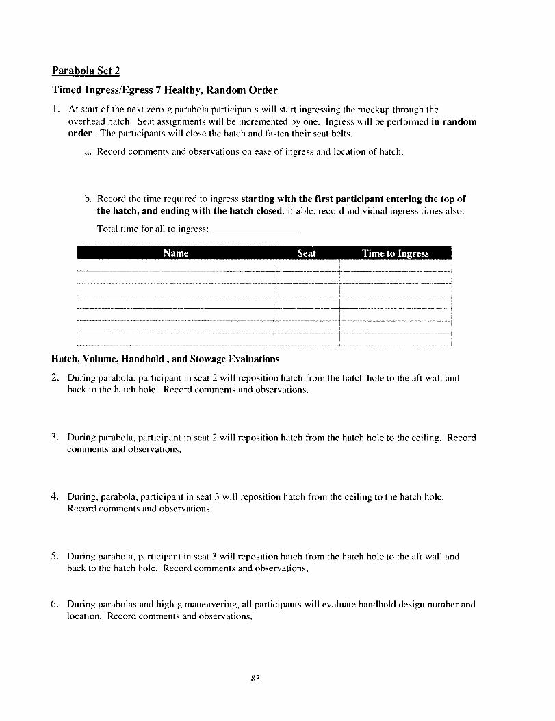
Parabola Set 2
Timed Ingress/Egress 7 Healthy, Random Order
l° At start of the next zero-g parabola participants will start ingressing the mockup through the
overhead hatch. Seat assignments will be incremented by one. Ingress will be performed in randomorder. The participants will close the hatch and fasten their seat belts.
a. Record comments and observations on ease of ingress and location of hatch.
b. Record the time required to ingress starting with the first participant entering the top of
the hatch, and ending with the hatch closed: if able, record individual ingress times also:
Total time for all to ingress:
Name Seat Time to Ingress
ii
I...................................................................................................................................................... i
L__................................................................................................................................................................................ i
Hatch, Volume, Handhold, and Stowage Evaluations
2. During parabola, participant in seat 2 will reposition hatch from the hatch hole to the aft wall andback to the hatch hole. Record comments and observations.
3. During parabola, participant in seat 2 will reposition hatch from the hatch hole to the ceiling. Recordcomments and observations.
4. During, parabola, participant in seat 3 will reposition hatch from the ceiling to the hatch hole.Record comments and observations.
5. During parabola, participant in seat 3 will reposition hatch from the hatch hole to the aft wall andback to the hatch hole. Record comments and observations.
6. During parabolas and high-g maneuvering, all participants will evaluate handhold design number andlocation. Record comments and observations.
83
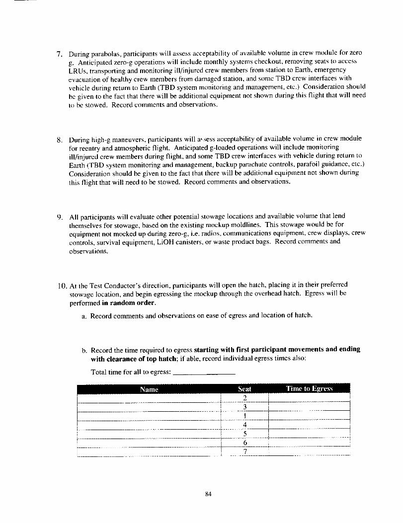
, During parabolas, participants will assess acceptability of available volume in crew module for zero
g. Anticipated zero-g operations will include monthly systems checkout, removing seats to access
LRUs, transporting and monitoring ill/injured crew members from station to Earth, emergency
evacuation of healthy crew members from damaged station, and some TBD crew interfaces with
vehicle during return to Earth (TBD system monitoring and management, etc.) Consideration should
be given to the fact that there will be additional equipment not shown during this flight that will needto be stowed. Record comments and observations.
. During high-g maneuvers, participants will a_.sess acceptability of available volume in crew module
for reentry and atmospheric flight. Anticipated g-loaded operations will include monitoring
ill/injured crew members during flight, and some TBD crew interfaces with vehicle during return to
Earth (TBD system monitoring and management, backup parachute controls, parafoil guidance, etc.)Consideration should be given to the fact that there will be additional equipment not shown during
this flight that will need to be stowed. Record comments and observations.
, All participants will evaluate other potential stowage locations and available volume that lend
themselves for stowage, based on the existing mockup moldlines. This stowage would be for
equipment not mocked up during zero-g, i.e. radios, communications equipment, crew displays, crew
controls, survival equipment, LiOH canisters, or waste product bags. Record comments andobservations.
10. At the Test Conductor's direction, participants will open the hatch, placing it in their preferred
stowage location, and begin egressing the mockup through the overhead hatch. Egress will be
performed in random order.
a. Record comments and observations on ease of egress and location of hatch.
b. Record the time required to egress starting with first participant movements and ending
with clearance of top hatch; if able, record individual egress times also:
Total time for all to egress:
;eat Time to Egress
, I4 I5
6
84
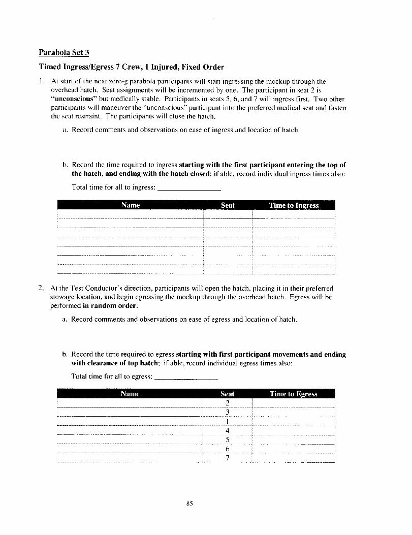
Parabola Set 3
Timed Ingress/Egress 7 Crew, 1 Injured, Fixed Order
I. At start of the next zero-g parabola participants will start ingressing the mockup through the
overhead hatch. Seat assignments will be incremented by one. The participant in seat 2 is"unconscious" but medically stable. Participants in seats 5, 6, and 7 will ingress first. Two other
participants will maneuver the "unconscious" participant into the preferred medical seat and fasten
the seat restraint. The participants will close the hatch.
a. Record comments and observations on ease of ingress and location of hatch.
b. Record the time required to ingress starting with the first participant entering the top of
the hatch, and ending with the hatch closed: if able, record individual ingress times also:
Total time for all to ingress:
Name Seat Time to Ingress
!
................................................................... .. ............................................. ÷....................................................................................... ,
iI !
. At the Test Conductor's direction, participants will open the hatch, placing it in their preferred
stowage location, and begin egressing the mockup through the overhead hatch. Egress wilt beperformed in random order.
a. Record comments and observations on ease of egress and location of hatch.
b. Record the time required to egress starting with first participant movements and ending
with clearance of top hatch: if able, record individual egress times also:
Total time for all to egress:
Name Seat Time to Egress2
3
4
5
6
7 r
85
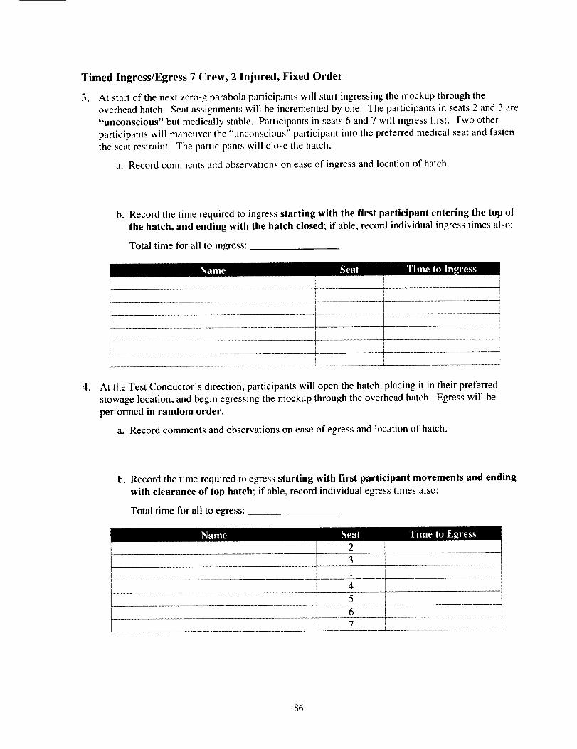
Timed Ingress/Egress 7 Crew, 2 Injured, Fixed Order
. At start of the next zero-g parabola participants will start ingressing the mockup through the
overhead hatch. Seat assignments will be incremented by one. The participants in seats 2 and 3 are
"unconscious" but medically stable. Participants in seats 6 and 7 will ingress first. Two other
participants will maneuver the "unconscious" participant into the preferred medical seat and fastenthe seat restraint. The participants will close the hatch.
a. Record comments and observations on ease of ingress and location of hatch.
b. Record the time required to ingress starting with the first participant entering the top of
the hatch, and ending with the hatch closed; if able, record individual ingress times also:
Total time for all to ingress:
Nam_
i
r I/
! i
! ....................................................i..........................t................................................................... I i
I
, At the Test Conductor's direction, participants will open the hatch, placing it in their preferred
stowage location, and begin egressing the mockup through the overhead hatch. Egress will be
performed in random order.
a. Record comments and observations on ease of egress and location of hatch.
b° Record the time required to egress starting with first participant movements and ending
with clearance of top hatch; if able, record individual egress times also:
Total time for all to egress:
Name
86
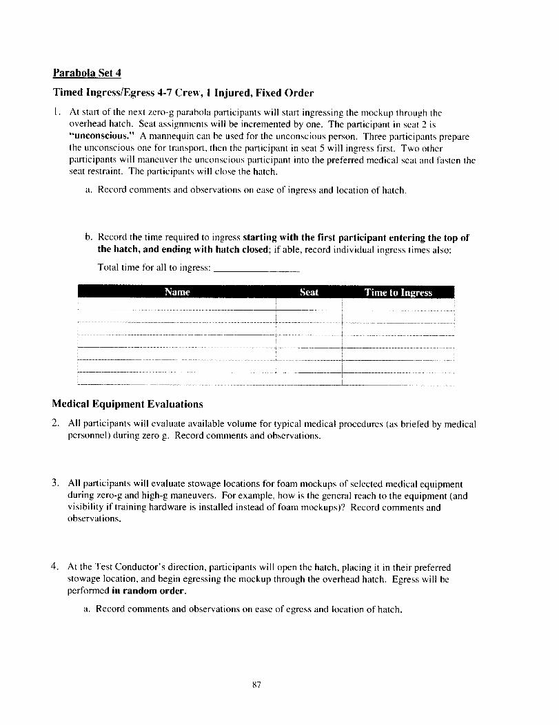
Parabola Set 4
Timed Ingress/Egress 4-7 Crew, 1 Injured, Fixed Order
l° At start of the next zero-g parabola participants will start ingressing the mockup through the
overhead hatch. Seat assignments will be incremented by one. The participant in seat 2 is
"unconscious." A mannequin can be used for the unconscious person. Three participants prepare
the unconscious one for transport, then the participant in seat 5 will ingress first. Two other
participants will maneuver the unconscious participant into the preferred medical seat and fasten theseat restraint. The participants will close the hatch.
a. Record comments and observations on ease of ingress and location of hatch.
b. Record the time required to ingress starting with the first participant entering the lop of
the hatch, and ending with hatch closed; if able, record individual ingress times also:
Total time for all to ingress:
Name Seat Time to Ingress
Medical Equipment Evaluations
2. All participants will evaluate available volume for typical medical procedures (as briefed by medical
personnel) during zero g. Record comments and observations.
° All participants will evaluate stowage locations for foam mockups of selected medical equipmentduring zero-g and high-g maneuvers. For example, how is the general reach to the equipment (and
visibility if training hardware is installed instead of foam mockups)? Record comments andobservations.
. At the Test Conductor's direction, participants will open the hatch, placing it in their preferredstowage location, and begin egressing the mockup through the overhead hatch. Egress will be
performed in random order.
a. Record comments and observations on ease of egress and location of hatch.
87
b. Record the time required to egress starting with first participant movements and ending
with clearance of top hatch: if able, record individual egress times also:
Total time for all to egress:
Seat Time to Egress
88
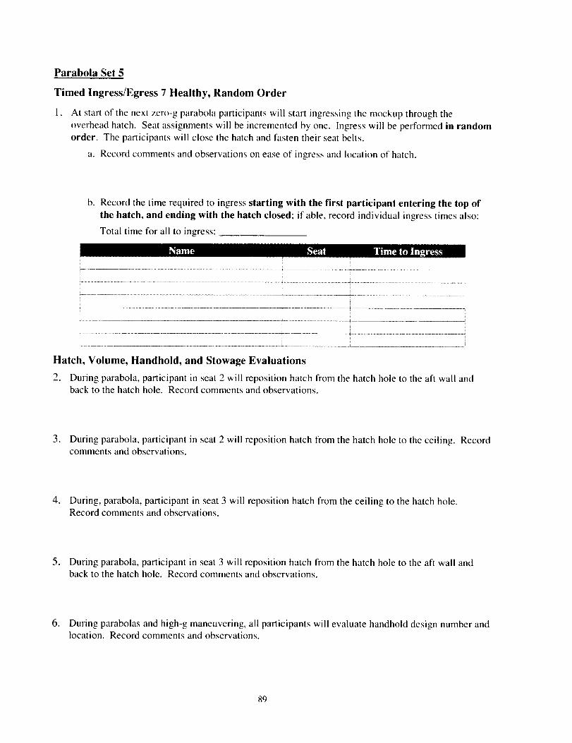
Parabola Set 5
Timed Ingress/Egress 7 Healthy, Random Order
1. At start of the next zero-g parabola participants will start ingressing the mockup through the
overhead hatch. Seat assignments will be incremented by one. Ingress will be performed in randomorder. The participants will close the hatch and fasten their seat belts.
a. Record comments and observations on ease of ingress and location of hatch.
b. Record the time required to ingress starting with the first participant entering the top of
the hatch, and ending with the hatch closed: if able, record individual ingress times also:
Total time for all to ingress:
Name Seat Time to Ingress
Hatch, Volume, Handhold, and Stowage Evaluations
2. During parabola, participant in seat 2 will reposition hatch from the hatch hole to the aft wall andback to the hatch hole. Record comments and observations.
3. During parabola, participant in seat 2 will reposition hatch from the hatch hole to the ceiling. Recordcomments and observations.
4. During, parabola, participant in seat 3 will reposition hatch from the ceiling to the hatch hole.Record comments and observations.
5. During parabola, participant in seat 3 will reposition hatch from the hatch hole to the aft wall andback to the hatch hole. Record comments and observations.
6. During parabolas and high-g maneuvering, all participants will evaluate handhold design number andlocation. Record comments and observations.
89
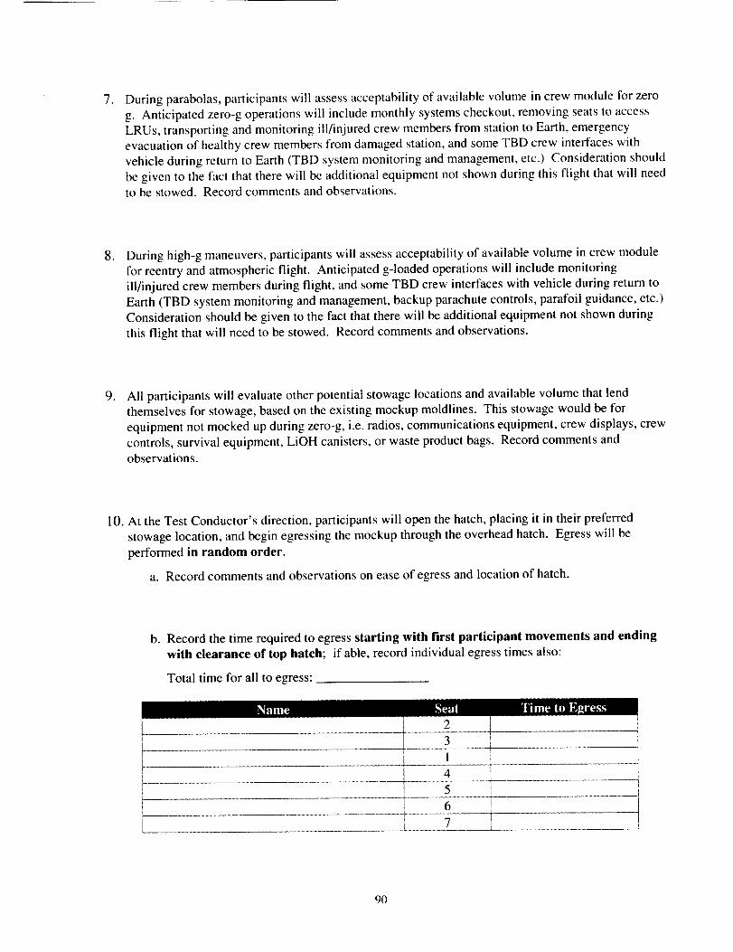
, During parabolas, participants will assess acceptability of available volume in crew module for zero
g. Anticipated zero-g operations will include monthly systems checkout, removing seats to access
LRUs, transporting and monitoring ill/injured crew members from station to Earth, emergencyevacuation of healthy crew members from damaged station, and some TBD crew interfaces with
vehicle during return to Earth (TBD system monitoring and management, etc.) Consideration should
be given to the fact that there will be additional equipment not shown during this flight that will needto be stowed. Record comments and observations.
. During high-g maneuvers, participants will assess acceptability of available volume in crew modulefor reentry and atmospheric flight. Anticipated g-loaded operations will include monitoring
ill/injured crew members during flight, and some TBD crew interfaces with vehicle during return toEarth (TBD system monitoring and management, backup parachute controls, parafoil guidance, etc.)
Consideration should be given to the fact that there will be additional equipment not shown during
this flight that will need to be stowed. Record comments and observations.
, All participants will evaluate other potential stowage locations and available volume that lendthemselves for stowage, based on the existing mockup moldlines. This stowage would be for
equipment not mocked up during zero-g, i.e. radios, communications equipment, crew displays, crewcontrols, survival equipment, LiOH canisters, or waste product bags. Record comments and
observations.
10. At the Test Conductor's direction, participants will open the hatch, placing it in their preferred
stowage location, and begin egressing the mockup through the overhead hatch. Egress will be
performed in random order.
a. Record comments and observations on ease of egress and location of hatch.
b. Record the time required to egress starting with first participant movements and ending
with clearance of top hatch; if able, record individual egress times also:
Total time for all to egress:
4I 5
6
90
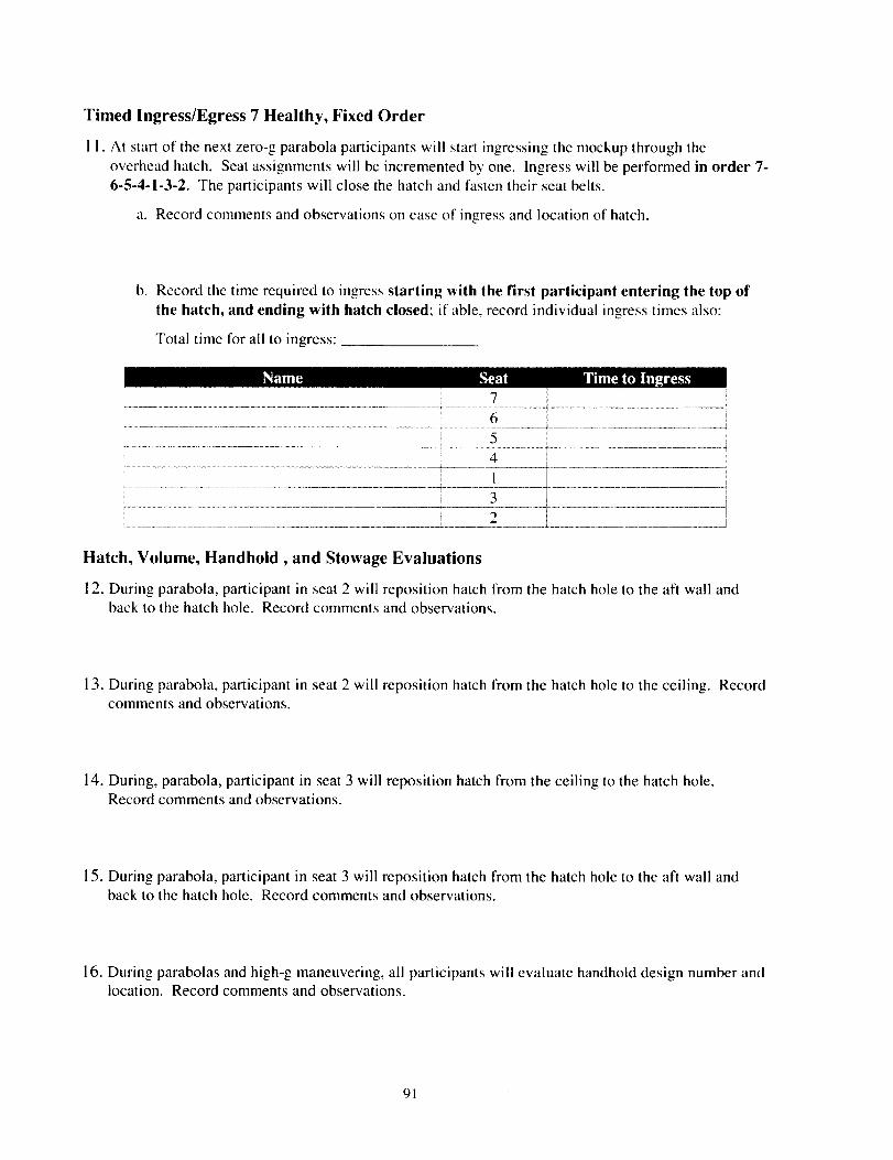
Timed Ingress/Egress 7 Healthy, Fixed Order
1 I. At start of the next zero-g parabola participants will start ingressing the mockup through the
overhead hatch. Seat assignments will be incremented by one. Ingress will be performed in order 7-
6-5-4-1-3-2. The participants will close the hatch and fasten their seat belts.
a. Record comments and observations on ease of ingress and location of hatch.
b. Record the time required to ingress starting with the first participant entering the top of
the hatch, and ending with hatch closed; if able, record individual ingress times also:
Total time for all to ingress:
Name Seat Time to IngressZ, 7
6
5
i 3 i J
Hatch, Volume, Handhold, and Stowage Evaluations
12. During parabola, participant in seat 2 will reposition hatch from the hatch hole to the aft wall andback to the hatch hole. Record comments and observations.
13. During parabola, participant in seat 2 will reposition hatch from the hatch hole to the ceiling. Recordcomments and observations.
14. During, parabola, participant in seat 3 will reposition hatch from the ceiling to the hatch hole.Record comments and observations.
15. During parabola, participant in seat 3 will reposition hatch from the hatch hole to the aft wall andback to the hatch hole. Record comments and observations.
16. During parabolas and high-g maneuvering, all participants will evaluate handhold design number andlocation. Record comments and observations.
91
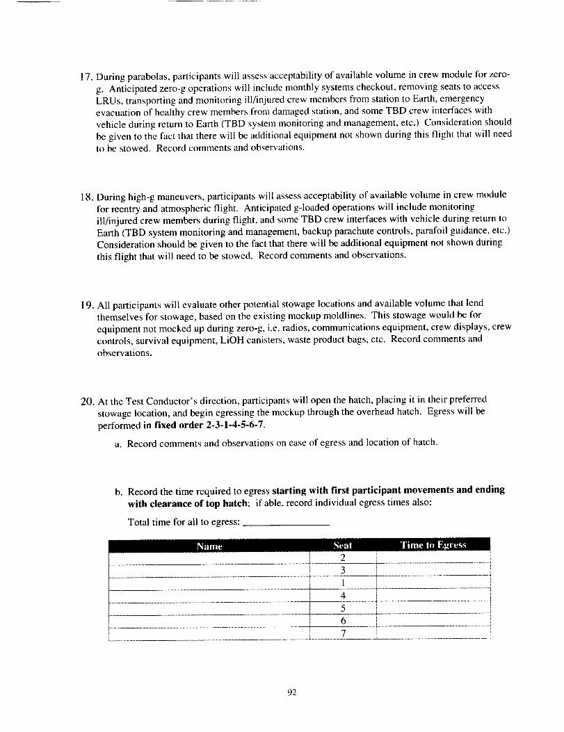
17.Duringparabolas,participantswill assessacceptabilityof availablevolumeincrewmoduleforzero-g. Anticipatedzero-goperationswill includemonthlysystemscheckout,removingseatstoaccessLRUs,transportingandmonitoringill/injuredcrewmembersfromstationtoEarth,emergencyevacuationof healthycrewmembersfromdamagedstation,andsomeTBDcrewinterfaceswithvehicleduringreturnto Earth(TBDsystemmonitoringandmanagement,etc.)Considerationshouldbegiventothefactthattherewill beadditionalequipmentnotshownduringthisflight thatwill needto bestowed.Recordcommentsandobservations.
18.Duringhigh-gmaneuvers,participantswill assessacceptabilityof availablevolumeincrewmodulefor reentryandatmosphericflight. Anticipatedg-loadedoperationswill includemonitoringill/injuredcrewmembersduringflight,andsomeTBD crewinterfaceswithvehicleduringreturntoEarth(TBDsystemmonitoringandmanagement,backupparachutecontrols,parafoilguidance,etc.)Considerationshouldbegiventothefactthattherewill beadditionalequipmentnotshownduringthisflightthatwill needto bestowed.Recordcommentsandobservations.
19.All participantswill evaluateotherpotentialstowagelocationsandavailablevolumethatlendthemselvesfor stowage,basedontheexistingmockupmoldlines.Thisstowagewouldbeforequipmentnotmockedupduringzero-g,i.e.radios,communicationsequipment,crewdisplays,crewcontrols,survivalequipment,LiOHcanisters,wasteproductbags,etc. Recordcommentsandobservations.
20. At theTestConductor'sdirection,participantswill openthehatch,placingit in theirpreferredstowagelocation,andbeginegressingthemockupthroughtheoverheadhatch.Egresswill beperformedin fixed order 2-3-1-4-5-6-7.
a. Record comments and observations on ease of egress and location of hatch.
b. Record the time required to egress starting with first participant movements and ending
with clearance of top hatch; if able, record individual egress times also:
Total time for all to egress:
Name
31 !4 t5 i
92
APPENDIX 2
7-Person KC-135 Flight Test Postflight Questionnaire
93
APPENDIX 2: POSTFLIGHT QUESTIONNAIRE
X-38 Project Seven Person Crew Module MockupKC-135 Evaluation
Subject Number:
Name: Test Date:
Number of spaceflights: Duration of longest:
Aviation experience: __ hours military, hours civilianI I
__ Male or__Female IHeight: I Weight:
General body description:
Directions:
The following questions will be used to determine your views on the acceptability of the X-38 crew
module. A six-point bipolar scale is used for all ratings. A rating of I is extremely negative (e.g. totally
unacceptable, no redeeming qualities in the design). A rating of 6 is extremely good (e.g. the design
can't be improved, don't change anything). Please circle the rating number that mostly closely describes
your view of the question. If you feel that ratings alone are inadequate to express your views, you may
comment in the space below the questions.
94
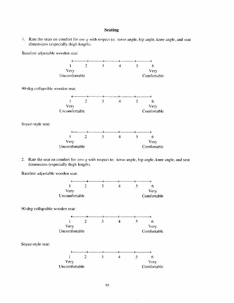
Seating
1. Rate the seats on comfort for one g with respect to: torso angle, hip angle, knee angle, and seat
dimensions (especially thigh length).
Baseline adjustable wooden seat:
+ .......... + .......... + .......... + .......... + .......... +
1 2 3 4 5 6
Very VeryUncomfortable Comfortable
90-deg collapsible wooden seat:
+ .......... + .......... + .......... + .......... + .......... +
1 2 3 4 5 6
Very VeryUncomfortable Comfortable
Soyuz-style seat:
+ .......... + .......... + .......... + .......... + .......... +
1 2 3 4 5 6
Very VeryUncomfortable Comfortable
2. Rate the seat on comfort for zero g with respect to: torso angle, hip angle, knee angle, and seat
dimensions (especially thigh length).
Baseline adjustable wooden seat:
+ .......... + .......... + .......... + .......... + .......... +
I 2 3 4 5 6
Very VeryUncomfortable Comfortable
90-deg collapsible wooden seat:
+ .......... + .......... + .......... + .......... + .......... +
1 2 3 4 5 6
Very VeryUncomfortable Comfortable
Soyuz-style seat:
+ .......... + .......... + .......... + .......... + .......... +
1 2 3 4 5 6
Very VeryUncomfortable Comfortable
95
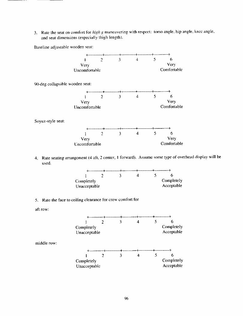
3. Ratetheseatoncomfortfor high g maneuvering with respect: torso angle, hip angle, knee angle,
and seat dimensions (especially thigh length).
Baseline adjustable wooden seat:
+ .......... + .......... + .......... + .......... + .......... +
I 2 3 4 5 6
Very VeryUncomfortable Comfortable
90-deg collapsible wooden seat:
+ .......... + .......... + .......... + .......... + .......... +
I 2 3 4 5 6
Very VeryUncomfortable Comfortable
Soyuz-style seat:
+ .......... + .......... + .......... + .......... + .......... +
1 2 3 4 5 6
Very VeryUncomfortable Comfortable
, Rate seating arrangement (4 aft, 2 center, 1 forward). Assume some type of overhead display will beused.
+ .......... + .......... + .......... + .......... + .......... +
1 2 3 4 5 6
Completely Completely
Unacceptable Acceptable
5. Rate the face to ceiling clearance for crew comfort for
aft row:
+ .......... + .......... + .......... + .......... + .......... +
1 2 3 4 5 6
Completely Completely
Unacceptable Acceptable
middle row:
+ .......... + .......... + .......... + .......... + .......... +
1 2 3 4 5 6
Completely Completely
Unacceptable Acceptable
96
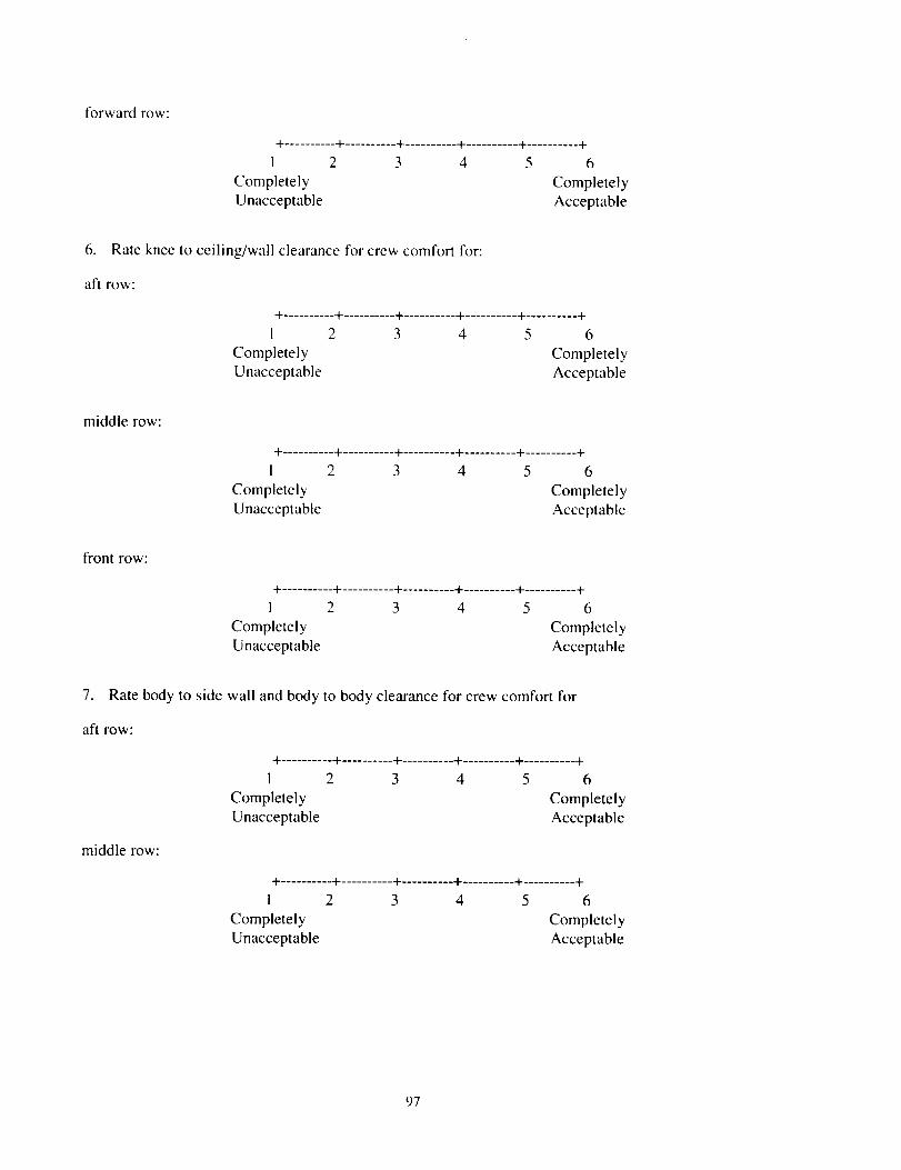
forwardrow:
+ .......... + .......... + .......... -t- .......... + .......... +
1 2 3 4 5 6
Completely Completely
Unacceptable Acceptable
6. Rate knee to ceiling/wall clearance for crew comfort for:
aft row:
+ .......... + .......... + .......... + .......... + .......... +
1 2 3 4 5 6
Completely Completely
Unacceptable Acceptable
middle row:
+ .......... + .......... + .......... + .......... + .......... +
I 2 3 4 5 6
Completely Completely
Unacceptable Acceptable
front row:
+ .......... + .......... + .......... + .......... + .......... +
1 2 3 4 5 6
Completely Completely
Unacceptable Acceptable
7. Rate body to side wall and body to body clearance for crew comfort for
aft row:
+ .......... + .......... + .......... + .......... + .......... +
1 2 3 4 5 6
Completely Completely
Unacceptable Acceptable
middle row:
+ .......... + .......... + .......... + .......... + .......... +
i 2 3 4 5 6
Completely Completely
Unacceptable Acceptable
97
forwardrow:
+ .......... + .......... + .......... + .......... + .......... +
I 2 3 4 5 6
Completely Completely
Unacceptable Acceptable
8. Which seat(s) are the best location for ill/injured crew members (circle and comment):
1234
56
7
9. Which seat(s) are the best location for crew member(s) interfacing with vehicle systems through a
computer (circle and comment).
1234
56
7
10. Which seat(s) did you ingress (circle and comment)?
1234
56
7
l°
Ingress/Egress
Rate ingress order for healthy crew members during station emergency:
+ .......... + .......... + .......... + .......... + .......... +
1 2 3 4 5 6
Always Use Always UseRandom Order Fixed Order
. Rate ingress order for ill/injured crew members for medical evacuation::
+ .......... + .......... + .......... + .......... + .......... +
1 2 3 4 5 6
Always Use Always UseRandom Order Fixed Order
98
3. Rateeaseof zero-gingressof healthycrewmembers.
+ .......... + .......... + .......... + .......... + .......... +
I 2 3 4 5 6
Very Very
Difficull Easy
4. Rate ease of zero-g ingress of ill/injured crew members.
+ .......... + .......... + .......... + .......... + .......... +
1 2 3 4 5 6
Very Very
Difficult Easy
5. Rate ease of zero-g egress of healthy crew members.
+ .......... + .......... + .......... + .......... + .......... +
1 2 3 4 5 6
Very Very
Difficult Easy
6. Rate anticipated ease of one-g egress of healthy deconditioned crew members.
+ .......... + .......... + .......... + .......... + .......... +
1 2 3 4 5 6
Very Very
Difficult Easy
Hatch
1. Rate the location of the hatch.
+ .......... + .......... + .......... + .......... + .......... +
! 2 3 4 5 6
Completely CompletelyUnacceptable Acceptable
. Rate adequacy of diameter of hatch hole for anticipated zero-g operations (ingress of healthy and
ill/injured crew members, passing crew equipment through).
+ .......... + .......... + .......... + .......... + .......... +
1 2 3 4 5 6
Completely Completely
Inadequate Adequate
99
° Rate adequacy of diameter of hatch hole for anticipated one-g operations (unaided and aided egress
of healthy and ill/injured deconditioned crew members).
+ .......... + .......... + .......... + .......... + .......... +
1 2 3 4 5 6
Completely Completely
Inadequate Adequate
. Rate acceptability of stowing hatch on aft wall.
+ .......... + .......... + .......... + .......... + .......... +
1 2 3 4 5 6
Completely Completely
Unacceptable Acceptable
. Rate acceptability of stowing hatch on ceiling.
+ .......... -I- .......... + .......... + .......... + .......... +
1 2 3 4 5 6
Completely Completely
Unacceptable Acceptable
.
Volume
Rate adequacy of volume in current configuration) for anticipated on-orbit station attached
operations (monthly systems checkout, removing seats for IFM and LRU replacement, etc.).
+ .......... + .......... + .......... + .......... + .......... +
1 2 3 4 5 6
Completely CompletelyInadequate Adequate
. Rate adequacy of volume for seven crew members in current configuration for anticipated post-
separation zero-g operations (systems activation and monitoring/interaction through displays and
controls, changing LiOH canisters, monitoring ill/injured crew members, and getting situated for
reentry).
+ .......... + .......... + .......... + .......... + .......... +
1 2 3 4 5 6
Completely Completely
Inadequate Adequate
1(_)
. Rate adequacy of volume for seven crew members in current configuration for anticipated
atmospheric flight and postlanding operation (systems monitoring/interaction through displays and
controls, parafoil guidance as manual backup, monitoring ill/injured crew members, and gettingsituated for landing and egress)
+ .......... + .......... + .......... + .......... + .......... +
I 2 3 4 5 6
Completely Completely
Inadequate Adequate
. Rate adequacy of volume to perform rudimentary medical care (as described by flight surgeons inpretest briefing).
+ .......... + .......... + .......... + .......... + .......... +
I 2 3 4 5 6
Completely Completely
Inadequate Adequate
Crew Equipment and Stowage
I. Rate adequacy of flight crew equipment access and stowage as tested.
+ .......... + .......... + .......... + .......... + .......... +
1 2 3 4 5 6
Completely Completely
Inadequate Adequate
. Rate adequacy of medical equipment access and stowage as tested:
+ .......... + .......... + .......... + .......... + .......... +
i 2 3 4 5 6
Completely Completely
Inadequate Adequate
3. Rate adequacy of crew module reach and visibility.
+ .......... + .......... + .......... + .......... + .......... +
I 2 3 4 5 6
Completely CompletelyInadequate Adequate
101
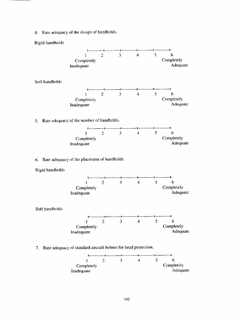
4. Rateadequacyofthedesignof handholds.
Rigidhandholds+ .......... + .......... + .......... + .......... + .......... +
1 2 3 4 5 6
Completely Completely
Inadequate Adequate
Soft handholds
+ .......... + .......... + .......... + .......... + .......... +
1 2 3 4 5 6
Completely CompletelyInadequate Adequate
. Rate adequacy of the number of handholds.
+ .......... + .......... + .......... + .......... + .......... +
1 2 3 4 5 6
Completely Completely
Inadequate Adequate
6. Rate adequacy of the placement of handholds.
Rigid handholds
+ .......... + .......... + .......... + .......... + .......... +
1 2 3 4 5 6
Completely Completely
Inadequate Adequate
Soft handholds
+ .......... + .......... + .......... + .......... + .......... +
1 2 3 4 5 6
Completely Completely
Inadequate Adequate
. Rate adequacy of standard aircraft helmet for head protection.
+.......... + .......... + .......... + .......... + .......... +
I 2 3 4 5 6
Completely CompletelyInadequate Adequate
102
l,
General
In general this questionnaire adequately expressed my views.
+ .......... + .......... + .......... -t-.......... + .......... +
I 2 3 4 5 6
Completely Completely
Inadequate Adequale
2. Other issues I would snggest addressing include:
3. Other comments I'd like to share are:
103

104
APPENDIX 3
ANOVA Summary Tables
105
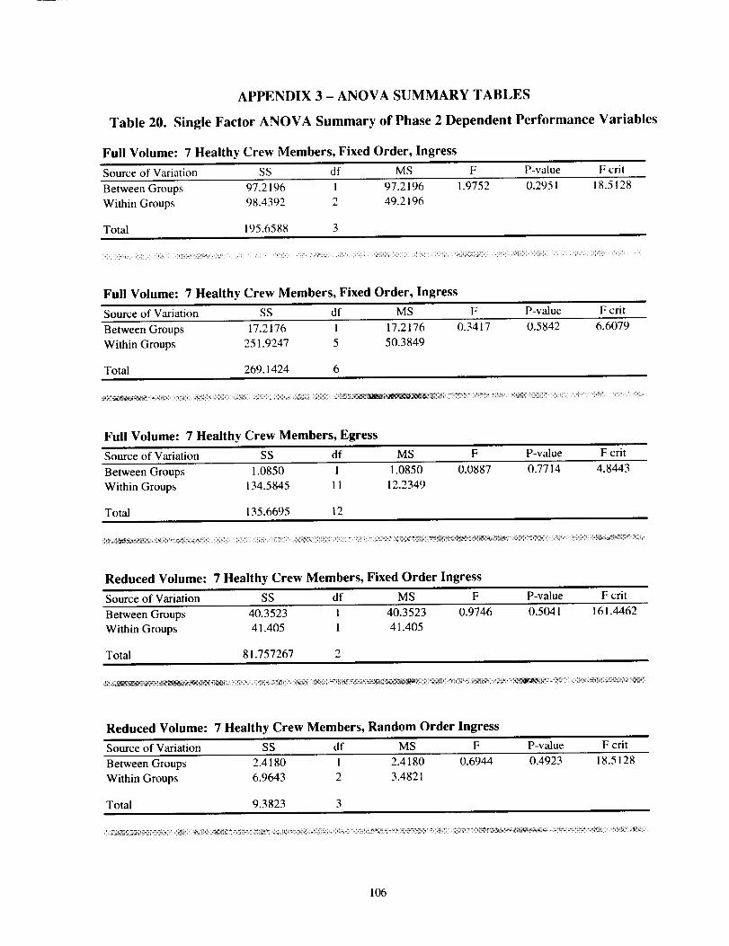
APPENDIX 3 - ANOVA SUMMARY TABLES
Table 20. Single Factor ANOVA Summary of Phase 2 Dependent Performance Variables
Full Volume: 7 Healthy Crew Members, Fixed Order, Ingress
Source of Variation SS df MS F P-value F crit
Between Groups 97.2196 1 97.2196 1.9752 0.2951 18.5128
Within Groups 98.4392 2 49.2196
Total 195.6588 3
Full Volume: 7 Healthy Crew Members, Fixed Order, Ingress
Source of Variation SS df MS F P-value F crit
Between Groups 17.2176 1 17.2176 0.3417 0.5842 6.6079
Within Groups 251.9247 5 50.3849
Total 269.1424 6
Full Volume: 7 Healthy Crew Members, Egress
Source of Variation SS df MS F P-value F crit
Between Groups 1.0850 1 1.0850 0.0887 0.7714 4.8443
Within Groups 134.5845 11 12.2349
Total 135.6695 12
Reduced Volume: 7 Healthy Crew Members, Fixed Order Ingress
Source of Variation SS df MS F P-value F crit
Between Groups 40.3523 1 40.3523 0.9746 0.5041 161.4462
Within Groups 41.405 1 41.405
Total 81.757267 2
Reduced Volume: 7 Healthy Crew Members, Random Order Ingress
Source of Variation SS df MS F P-value F crit
Between Groups 2.4180 ! 2.4180 0.6944 0.4923 18.5128
Within Groups 6.9643 2 3.4821
Total 9.3823 3
106
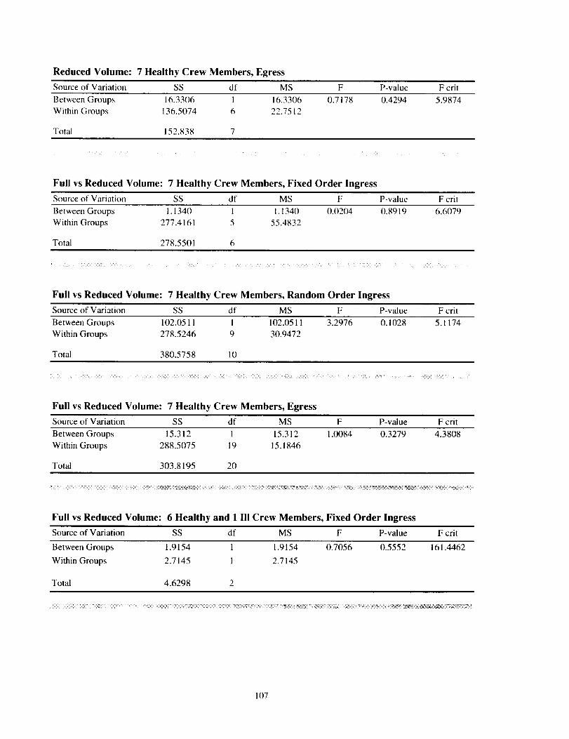
Reduced Volume: 7 Healthy Crew Members, Egress
Source of Variation SS df MS F P-value F crit
Between Groups 16.3306 1 16.3306 0.7178 0.4294 5.9874
Within Groups 136.5074 6 22.7512
Total 152.838 7
Full vs Reduced Volume: 7 Healthy Crew Members, Fixed Order Ingress
Source of Variation SS df MS F P-value F crit
Between Groups 1.1340 1 1. t 340 0.0204 0.8919 6.6079
Within Groups 277.4161 5 55.4832
Total 278.5501 6
Full vs Reduced Volume: 7 Healthy Crew Members, Random Order Ingress
Source of Variation SS df MS F P-value F crit
Between Groups 102.0511 1 102.0511 3.2976 0.1028 5.1174
Within Groups 278.5246 9 30.9472
Total 380.5758 10
Full vs Reduced Volume: 7 Healthy Crew Members, Egress
Source of Variation SS df MS F P-value F crit
Between Groups 15.312 1 15.312 1.0084 0.3279 4.3808
Within Groups 288.5075 19 15.1846
Total 303.8195 20
Full vs Reduced Volume: 6 Healthy and 1 Ill Crew Members, Fixed Order Ingress
Source of Variation SS df MS F P-value F crit
Between Groups 1.9154 1 1.9154 0.7056 0.5552 161.4462
Within Groups 2.7145 1 2.7145
Total 4.6298 2
ii iiiiiiiiii!!i!! iiiiiiiiiiiiii_i!_i_ii!i _i_ i!ii_i_iii:i!'_iill _i !i_ii i !ii iii ii i ii_/! i !iii_i_i_i_i!_i ilii_!iiiii_i_i_!ii_ __ !i__ili__ i_i_ ii_i_i _i _!_ii_i_iii_iiiil! _! __!_! i_i!_/_!_!l!_ii_i_!!! !!_i i_i_ ii_il_i_!iiii!iiiii_iii!iii l ii_ii iii_i_ _i_ _i_ _,ili'_ _ _ii_ _ __ _ !̧
107
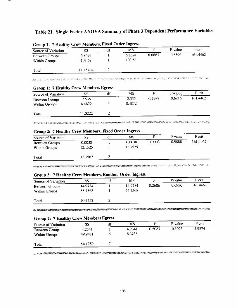
Table 21. Single Factor ANOVA Summary of Phase 3 Dependent Performance Variables
Group 1:7 Healthy Crew Members, Fixed Order Ingress
Source of Variation SS df MS F P-value F crit
Between Groups 6.8694 1 6.8694 0.0663 0.8396 161.4462
Within Groups 103.68 1 103.68
Total 110.5494 2
Group 1:7 Healthy Crew Members Egress
Source of Variation SS df MS F P-value F crit
Between Groups 2.535 1 2.535 0.2987 0.6816 161.4462
Within Groups 8.4872 1 8.4872
Total 11.0222 2
_,__U ¸_¸i_ _ i ¸¸¸_i_¸¸_ _ -_ _ _ iiii! i_iiiiiii!iiii_i_I_ i: ii!_ _i_i_ i_ i_ _ i _%_i_!_i_i_!_i!_i_®_i_iiii_iii_iii_!_!!_`_!!_ii_i_i_i_i_i_i_i_ ¸i_!¸_¸i_iiiiiii_iiii_iii!i iiiii!iii̧
Group 2:7 Healthy Crew Members, Fixed Order Ingress
Source of Variation SS df MS F P-value F crit
Between Groups 0.0038 1 0.0038 0.0003
Within Groups 12.1525 1 12.1525
Total 12.1562 2
0.9888 161.4462
Group 2:7 Healthy Crew Members, Random Order Ingress
Source of Variation SS df MS F P-value F crit
Between Groups 14.9784 1 14.9784 0.2686 0.6956 161.4462
Within Groups 55.7568 1 55.7568
Total 70.7352 2
Group 2:7 Healthy Crew Members Egress
Source of Variation SS df MS F P-value F crit
Between Groups 4.2341 1 4.2341 0.5087 0.5025 5.9874
Within Groups 49.9411 6 8.3235
Total 54.1752 7
108
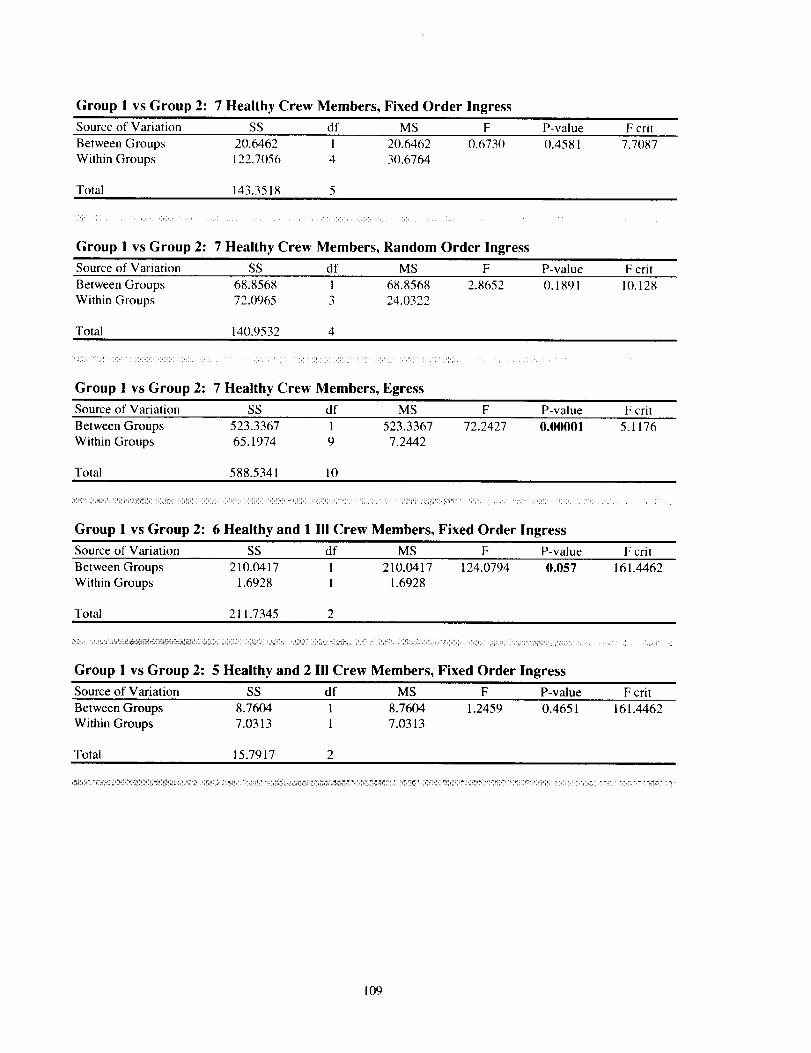
Group 1 vs Group 2:7 Healthy Crew Members, Fixed Order Ingress
Source of Variation SS df MS F P-value F crit
Between Groups 20.6462 1 20.6462 0.6730 0.4581 7.7087Within Groups 122.7056 4 30.6764
Total 143.3518 5
Group 1 vs Group 2:7 Healthy Crew Members, Random Order Ingress
Source of Variation SS df MS F P-value F crit
Between Groups 68.8568 1 68.8568 2.8652 0.1891 10.128
Within Groups 72.0965 3 24.0322
Total 140.9532 4
Group 1 vs Group 2:7 Healthy Crew Members, Egress
Source of Variation SS df MS F P-value F crit
Between Groups 523.3367 1 523.3367 72.2427 0.00001 5.1176
Within Groups 65.1974 9 7.2442
Total 588.5341 10
Group 1 vs Group 2:6 Healthy and 1 III Crew Members, Fixed Order Ingress
Source of Variation SS df MS F P-value F crit
Between Groups 210.0417 1 210.0417 124.0794 0.057 161.4462
Within Groups 1.6928 1 1.6928
Total 211.7345 2
Group 1 vs Group 2:5 Healthy and 2 I!1 Crew Members, Fixed Order Ingress
Source of Variation SS df MS F P-value F crit
Between Groups 8.7604 1 8.7604 1.2459 0.4651 161.4462
Within Groups 7.0313 1 7.0313
Total 15.7917 2
109
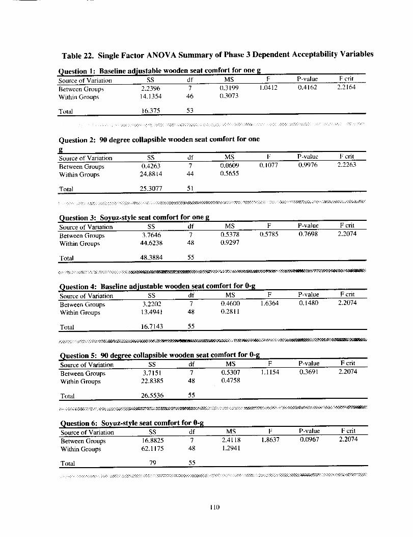
Table 22. Single Factor ANOVA Summary of Phase 3 Dependent Acceptability Variables
Question 1: Baseline adjustable wooden seat comfort for oneSource of Variation SS df MS F P-value F crit
Between Groups 2.2396 7 0.3199 1.0412Within Groups 14.1354 46 0.3073
Total 16.375 53
0.4162 2.2164
Question 2:90 degree collapsible wooden seat comfort for one
gSource of Variation SS df MS F P-value F crit
Between Groups 0.4263 7 0.0609 0.1077 0.9976 2.2263
Within Groups 24.8814 44 0.5655
Total 25.3077 51
Question 3: So_,uz-st_'le seat comfort for one BSource of Variation SS df MS F P-value F crit
Between Groups 3.7646 7 0.5378 0.5785Within Groups 44.6238 48 0.9297
Total 48.3884 55
0.7698 2.2074
_ i_i! !iIi_: iii_i _i_i_ii !i_i_ _ i_i i !_i_iii!_iiii!!!;/ii_ii!i_ii ¸ i_ _ _ _ _!!__"_'__ ¸L_!i_k_'_'_ i
Question 4: Baseline adjustable wooden seat comfort for 0-_Source of Variation SS df MS F P-value F crit
Between Groups 3.2202 7 0.4600 1.6364
Within Groups 13.4941 48 0.2811
Total 16.7143 55
0.1480 2.2074
Question 5:90 de[[ree collapsible wooden seat comfort for 0-[_Source of Variation SS df MS F P-value F crit
Between Groups 3.7151 7 0.5307 1.1154 0.3691
Within Groups 22.8385 48 0.4758
Total 26.5536 55
2.2074
Question 6: So_,uz-st_'le seat comfort for 0-[_Source of Variation SS df MS F P-value F crit
Between Groups 16.8825 7 2.4118 1.8637 0.0967
Within Groups 62.1175 48 1.2941
Total 79 55
2.2074
110
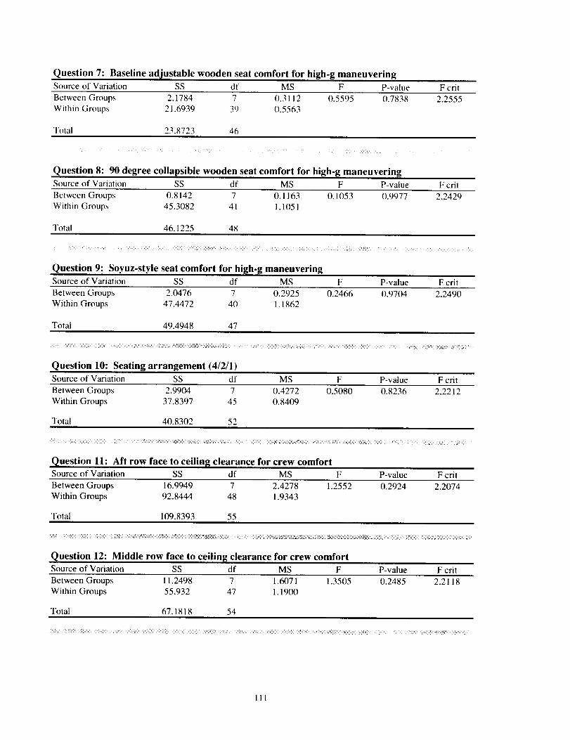
Question7: Baselineadjustablewoodenseatcomfortfor high-g maneuvering
Source of Variation SS df MS F P-value F crit
Between Groups 2.1784 7 0.3112 0.5595 0.7838 2.2555
Within Groups 21.6939 39 0.5563
Total 23.8723 46
Question 8:90 degree collapsible wooden seat comfort for high-g maneuvering
Source of Variation SS df MS F P-value F crit
Between Groups (1.8142 7 0.1163 O. 1053 0.9977 2.2429Within Groups 45.3082 41 1.1051
Total 46.1225 48
Question 9: Soyuz-style seat comfort for high-g maneuvering
Source of Variation SS df MS F P-value F crit
Between Groups 2.0476 7 0.2925 0.2466 0.9704 2.2490
Within Groups 47.4472 40 1.1862
Total 49.4948 47
Question 10: Seating arrangement (4/2/1t
Source of Variation SS df MS F P-value F crit
Between Groups 2.9904 7 0.4272 0.5080 0.8236 2.2212
Within Groups 37.8397 45 0.8409
Total 40.8302 52
Question 11: Aft row face to ceilin[_ clearance for crew comfortSource of Variation SS df MS F P-value F crit
Between Groups 16.9949 7 2.4278 1.2552 0.2924 2.2074
Within Groups 92.8444 48 1.9343
Total 109.8393 55
Question 12: Middle row face to ceilin[_ clearance for crew comfort
Source of Variation SS df MS F P-value F crit
Between Groups 11.2498 7 1.6071 1.3505 0.2485 2.2118Within Groups 55.932 47 1.1900
Total 67.1818 54
!i)!!i i@! !!!ili_!ii)_i ii!iiii ii i_! ! Yiiii i_il i if! iiiii:(!i! iii i iiiii iii i _;!! ii _i i ;¸ i i:i= ii i;! ii ;iii iil;i _i ii :_i _ _ _=_i_!_ ¸ _ i : = = _:_ _ _ _ _ _! _ _<_
111
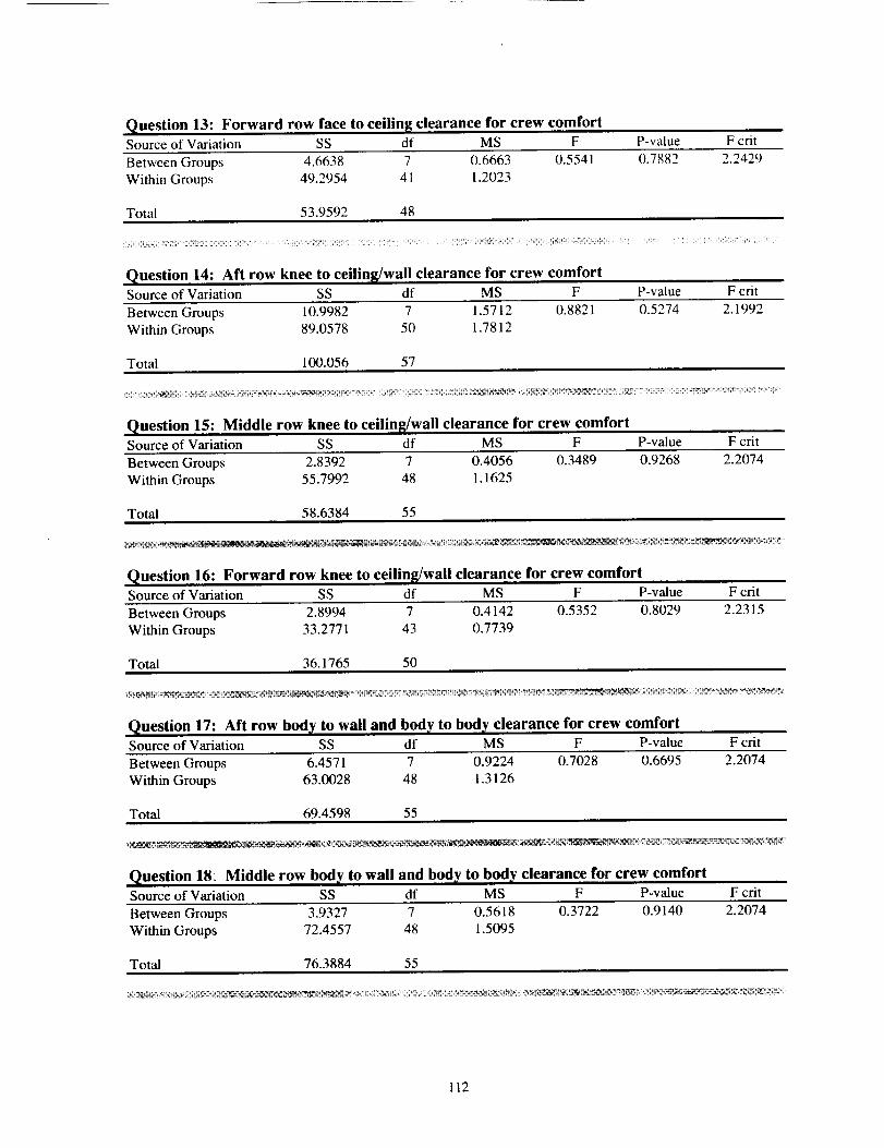
Question 13: Forward row face to ceilin_ clearance for crew comfortSource of Variation SS df MS F P-value F crit
Between Groups 4.6638 7 0.6663 0.5541
Within Groups 49.2954 41 1.2023
Total 53.9592 48
0.7882 2.2429
Question 14: Aft row knee to ceilin[[/wall clearance for crew comfortSource of Variation SS df MS F P-value F crit
Between Groups 10.9982 7 1.5712 0.8821 0.5274
Within Groups 89.0578 50 1.7812
Total 100.056 57
2.1992
iii_ii_i_i_i_ii_;_t iiiii_iii_i_ii_ _,:__i_!_!_! _i_t_ti ;_':_/_i_'_t _ i_tTi iii_iti!iiii_i_ii!ii_tiiili_ii_i_i_._!t !_ i_ _-_i!!_i _: _!_ _ _ii!ii_it_i__i_!_ iiI_i i̧¸_¸!iiiiii__il !ii:i_! _!_!_i!_ iiii!i_i:_iii_iii_iii_!ii_i!ii!i:!_!_
Question 15: Middle row knee to ceilin_/wall clearance for crew comfortSource of Variation SS df MS F P-value F crit
Between Groups 2.8392 7 0.4056 0.3489 0.9268
Within Groups 55.7992 48 1.1625
Total 58.6384 55
2.2074
Question 16: Forward row knee to ceilin_/wall clearance for crew comfortSource of Variation SS df MS F P-value F crit
Between Groups 2.8994 7 0.4142 0.5352 0.8029
Within Groups 33.2771 43 0.7739
Total 36.1765 50
2.2315
Question 17: Aft row body to wall and body to body clearance for crew comfortSource of Variation SS df MS F P-value F crit
Between Groups 6.4571 7 0.9224 0.7028 0.6695 2.2074
Within Groups 63.0028 48 1.3126
Total 69.4598 55
Question 18: Middle row body to wall and body to body clearance for crew comfortSource of Variation SS df MS F P-value F crit
Between Groups 3.9327 7 0.5618 0.3722 0.9140 2.2074
Within Groups 72.4557 48 1.5095
Total 76.3884 55
112
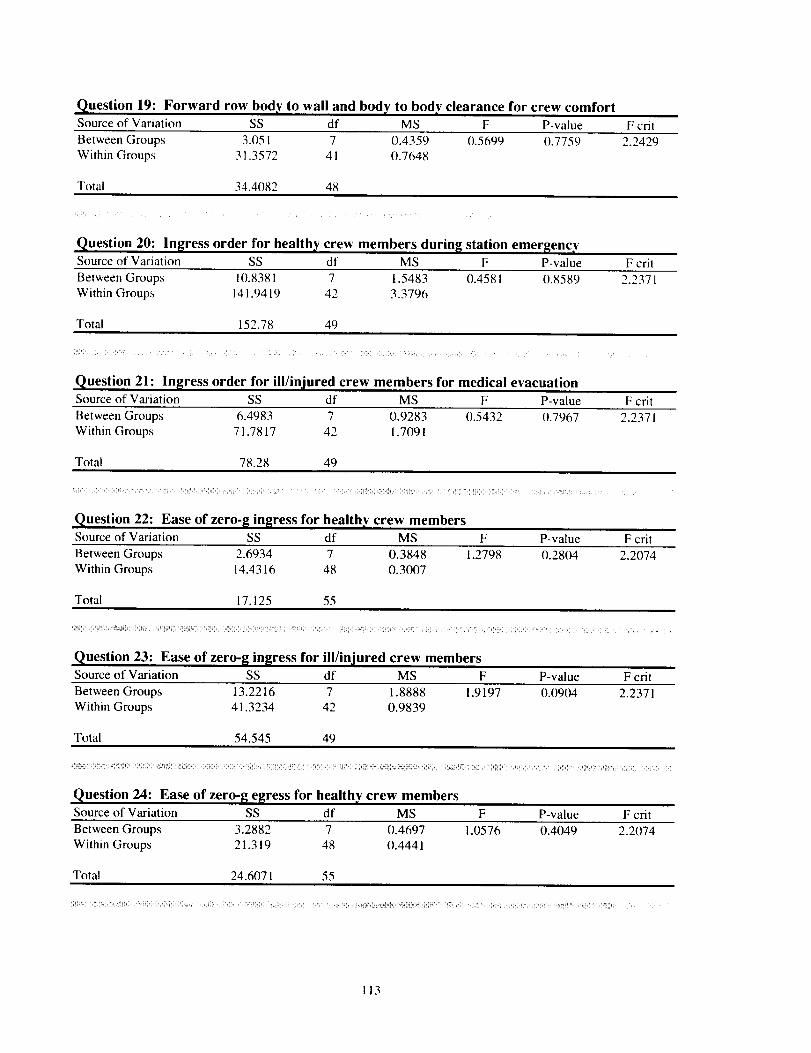
Question19: Forward row bodv to wall and body to body clearance for crew comfortSource of Variation SS df MS F P-value F crit
Between Groups 3.051 7 0.4359 0.5699 0.7759 2.2429Within Groups 31.3572 41 0.7648
Total 34.4082 48
i< ¸ i
Question 20: In[[ress order for healthy crew members durin[_ station emergencySource of Variation SS df MS F P-value F cril
Between Groups 10.8381 7 1.5483 0.4581 0.8589Within Groups 141.9419 42 3.3796
Total 152.78 49
2.2371
Question 21: In[[ress order for ill/injured crew members for medical evacuation
Source of Variation SS df MS F P-value F crit
Between Groups 6.4983 7 0.9283 0.5432 0.7967 2.2371
Within Groups 71.7817 42 1.7091
Total 78.28 49
{1: !' .... T ":11 i!" 21
Question 22: Ease of zero-[_ in[[ress for healthy crew membersSource of Variation SS df MS F P-value F crit
Between Groups 2.6934 7 0.3848 1.2798 0.2804 2.2074
Within Groups 14.4316 48 0.3007
Total 17.125 55
Question 23: Ease of zero-[_ in[[ress for ill/injured crew members
Source of Variation SS df MS F P-value F crit
Between Groups 13.2216 7 1.8888 1.9197 0.0904 2.2371Within Groups 41.3234 42 0.9839
Total 54.545 49
Question 24: Ease of zero-[_ e[[ress for healthv crew membersSource of Variation SS df MS F P-value F cnt
Between Groups 3.2882 7 0.4697 1.0576 0.4049 2.2074
Within Groups 21.319 48 0.4441
Total 24.6071 55
i!iiiiiiiii_iiii ii{!ii!iiii417 ili iiiiiii_iiiiiii_iiiiiiiiii_ii!!_i iiilii i!ii{iii i ii ii! i !!ii!iiiiii_i_ii!iii!iii_i i i i iil ii!(i_!i! ?_i, ili!!iiii_i;_i_ii!_!,-!}_iiiiii}_ii}{_ii=iiii!i:i! i =!_ _! i!i! i iii< !_iS_i ilii{i! iili!iii?ii_ U: _ii!_ ¸ iii iiiiii:!!2il _i _
113
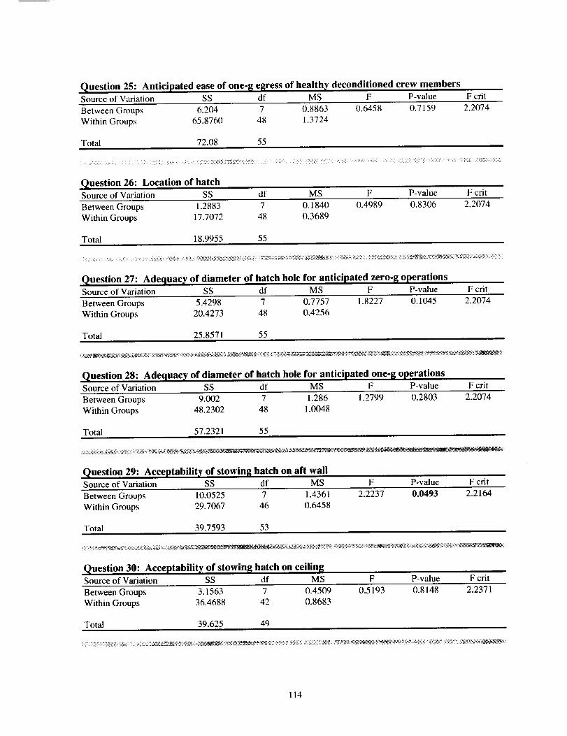
Question 25: Anticipated ease of one-8 esress of healthy deconditioned crew membersSource of Variation SS df MS F P-value F crit
Between Groups 6.204 7 0.8863 0.6458 0.7159 2.2074
Within Groups 65.8760 48 1.3724
Total 72.08 55
ii_ /;i;iiiii + x : i iii ili iil i ii ;ii!_;!iiii;iiiii;i;_i!iiii_¢!i_iiii_ii_!_!!!!!i!ii!!i!:iiii;i!/;; iii%i;i_!iiiii;ii;iiiii!iiiiii!ii_i_;iii! _̧¸_!Ui¸¸¸¸i;¸¸i¸;_ii¸i¸¸¸¸;/i;¸¸!¸¸iiil;¸ii¸¸i¸ii;i?ili!ill!i!!!i_i!!!iiiiiiiiiiiiiiii;iii_i;!!/i;;!T_!i_!i:i_!!!!i_!ii!!iiii!iiiii!i
Question 26: Location of hatchSource of Variation SS df MS F P-value F crit
Between Groups 1.2883 7 O. 1840 0.4989 0.8306 2.2074
Within Groups 17.7072 48 0.3689
Total 18.9955 55
;_i__ _ __ _ _i ,,; _ _:i_i_i_+_!i_iii_iiiiii!_;i_!!i_!_S_#2._iiii_ii_ii_i_i_!_i_i_`_i!_i_ii_ii_`g_ii_iiiiiiiiii_i_i_!ii!_i_i_!_i;ii_!i_ iiii¸;i¸i_i,'g,_q_ii_;ii_i__i_!_iiiii
Question 27: Adequacy of diameter of hatch hole for anticipated zero-8 operationsSource of Variation SS df MS F P-value F crit
Between Groups 5.4298 7 0.7757 1.8227Within Groups 20.4273 48 0.4256
Total 25.8571 55
0.1045 2.2074
t_2._:h_# _,. _ ,_.: _ ........ _,_#_,_ , _&_ ...... _ g_tt;,_ t_:_ , _ _N_ _ _;_ ;_.._,__'_
Question 28: Adequacy of diameter of hatch hole for anticipated one-[_ operationsSource of Variation SS df MS F P-value F crit
Between Groups 9.002 7 1.286 1.2799
Within Groups 48.2302 48 1.0048
Total 57.2321 55
0.2803 2.2074
Question 29: Acceptability of stowin8 hatch on aft wallSource of Variation SS df MS F P-value F crit
Between Groups 10.0525 7 1.4361 2.2237 0.0493Within Groups 29.7067 46 0.6458
Total 39.7593 53
2.2164
Question 30: Acceptability of stowin8 hatch on ceilin[[Source of Variation SS df MS F P-value F crit
Between Groups 3.1563 7 0.4509 0.5193
Within Groups 36.4688 42 0.8683
Total 39.625 49
0.8148 2.2371
114
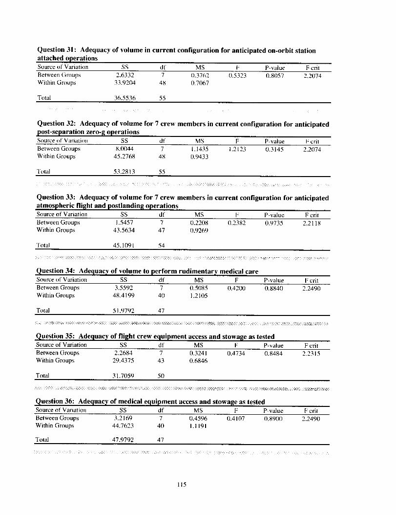
Question 31: Adequacy of volume in current configuration for anticipated on-orbit station
attached operationsSource of Variation SS df MS F P-value F crit
Between Groups 2.6332 7 0.3762 0.5323 0.8057 2.2074
Within Groups 33.9204 48 0.7067
Total 36.5536 55
Question 32: Adequacy of volume for 7 crew members in current configuration for anticipated
post-separation zero-[g operations
Source of Variation SS df MS F P-value F cril
Between Groups 8.(X)44 7 I. 1435 1.. 1.3 0.3145
Within Groups 45.2768 48 0.9433
Total 53.2813 55
2.2074
Question 33: Adequacy of volume for 7 crew members in current configuration for anticipated
atmospheric flight and postlanding operations
Source of Variation SS df MS F P-value F crit
Between Groups 1.5457 7 0.2208 0.2382 0.9735 2.2118
Within Groups 43.5634 47 0.9269
Total 45.1091 54
.................. _ _ , I" _ _
Question 34: Adequacy of volume to perform rudimentary medical careSource of Variation SS df MS F P-value F crit
Between Groups 3.5592 7 0.5085 0.4200 0.8840 2.2490
Within Groups 48.4199 40 1.2105
Total 51.9792 47
Question 35: Adequacy, of fli[[ht crew equipment access and stowa[[e as tested
Source of Variation SS df MS F P-value F crit
Between Groups 2.2684 7 0.3241 0.4734 0.8484 2.2315
Within Groups 29.4375 43 0.6846
Total 31.7059 50
il i i!iiiiiiii i!iii!iiil!ill,ill !iil)_l_! iiii_i!_ili_i_ii i_i iii!i_!!_ili_ii i!ii_il_i_ii_i_i i_!i_!_iii!_i_ilil _ili!i_i_!_!i!ii!i!i_i i!ii!i,'i_iii:iiii_i!i̧ il ii!_ ii!:!_ii_!__ i__ _i_!i!_!i_i_i _i_ _ _ Ii i_i !ilii i_i_i !_ii!_L'. i;ii_i_i_l_:i_ i_il i_ii_i_i_ii iiii_iii_ _!!_iii_i_ _ i_-¢,__,i
Question 36: Adequacy, of medical equipment access and stowa[je as testedSource of Variation SS df MS F P-value F crit
Between Groups 3.2169 7 0.4596 0.4107 0.89(X) 2.2490
Within Groups 44.7623 40 1.1191
Total 47.9792 47
115
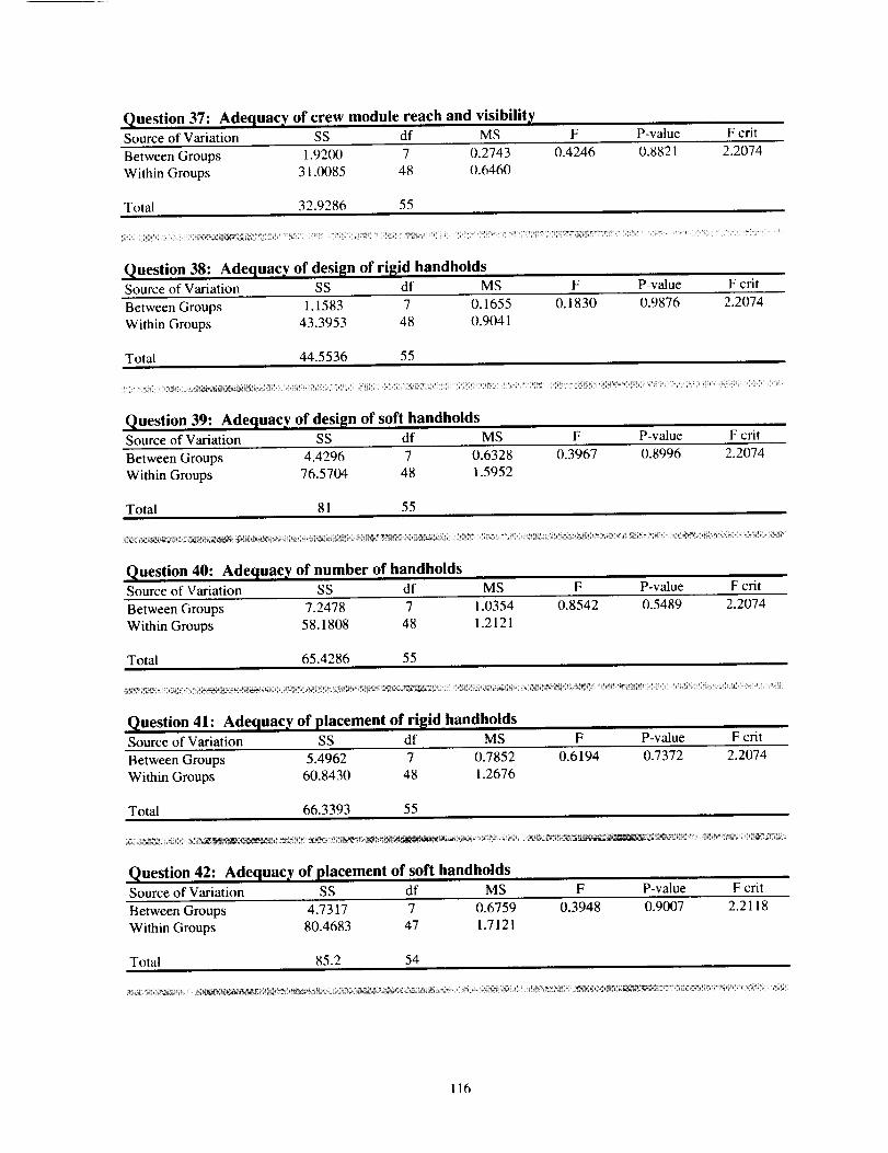
Question 37: Adequacy of crew module reach and visibilitySource of Variation SS df MS F P-value F crit
Between Groups 1.9200 7 0.2743 0.4246 0.8821 2.2074
Within Groups 31.0085 48 0.6460
Total 32.9286 55
Question 38: Adequacy of design of rigid handholdsSource of Variation SS df MS F P-value F crit
Between Groups 1.1583 7 0.1655 0.1830 0.9876 2.2074
Within Groups 43.3953 48 0.9041
Total 44.5536 55
Question 39: Adequacy of desit_n of soft handholdsSource of Variation SS df MS F P-value F crit
Between Groups 4.4296 7 0.6328 0.3967 0.8996 2.2074
Within Groups 76.5704 48 1.5952
Total 81 55
Question 40: Adequacy of number of handholdsSource of Variation SS df MS F P-value F crit
Between Groups 7.2478 7 1.0354 0.8542 0.5489 2.2074
Within Groups 58.1808 48 1.2121
Total 65.4286 55
Question 41: Adequac_ of placement of ri[[id handholdsSource of Variation SS df MS F P-value F crit
Between Groups 5.4962 7 0.7852 0.6194 0.7372 2.2074
Within Groups 60.8430 48 1.2676
Total 66.3393 55
_ _/_ _ _ _,_-_ _ _-_ __',_ _ _ii li_i_ii_iii iiii_i_i!!_iii_iii_ I_;_'_! _i_! ¸!¸!ii_¸_¸_ _
Question 42: Adequacy, of placement of soft handholdsSource of Variation SS df MS F P-value F crit
Between Groups 4.7317 7 0.6759 0.3948 0.9007 2.2118
Within Groups 80.4683 47 1.7121
Total 85.2 54
116
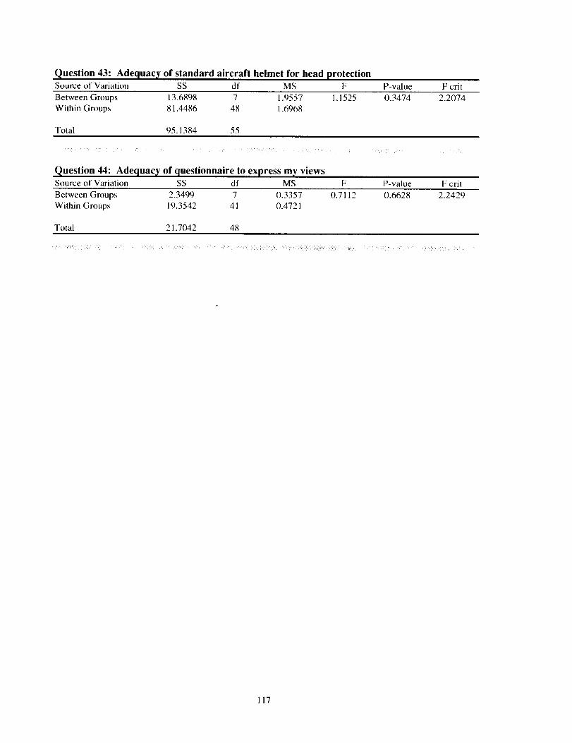
Question 43: Adequacy of standard aircraft helmet for head protectionSource of Variation SS df MS F P-value F crit
Between Groups 13.6898 7 1.9557 1.1525 0.3474 2.2074Within Groups 81.4486 48 1.6968
Total 95.1384 55
Question 44: Adequacy of questionnaire to express my viewsSource of variation SS df MS F P-value F crit
Between Groups 2.3499 7 0.3357 0.7112 0.6628 2.2429
Within Groups 19.3542 41 0.4721
Total 21.7042 48
!i i ! ! _ iliil iiiiiiiii!:iiiiiiiii!ii! ii i _ i!ii _ ii!i !_ iiiiiii i
117
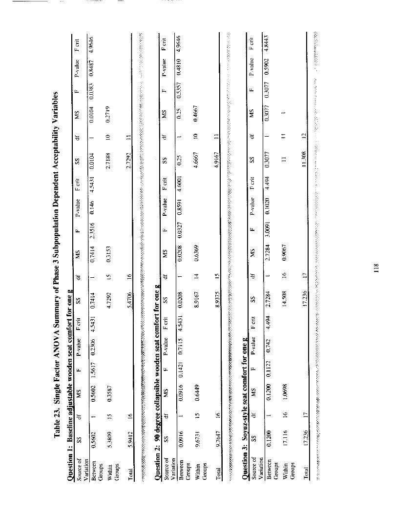
m
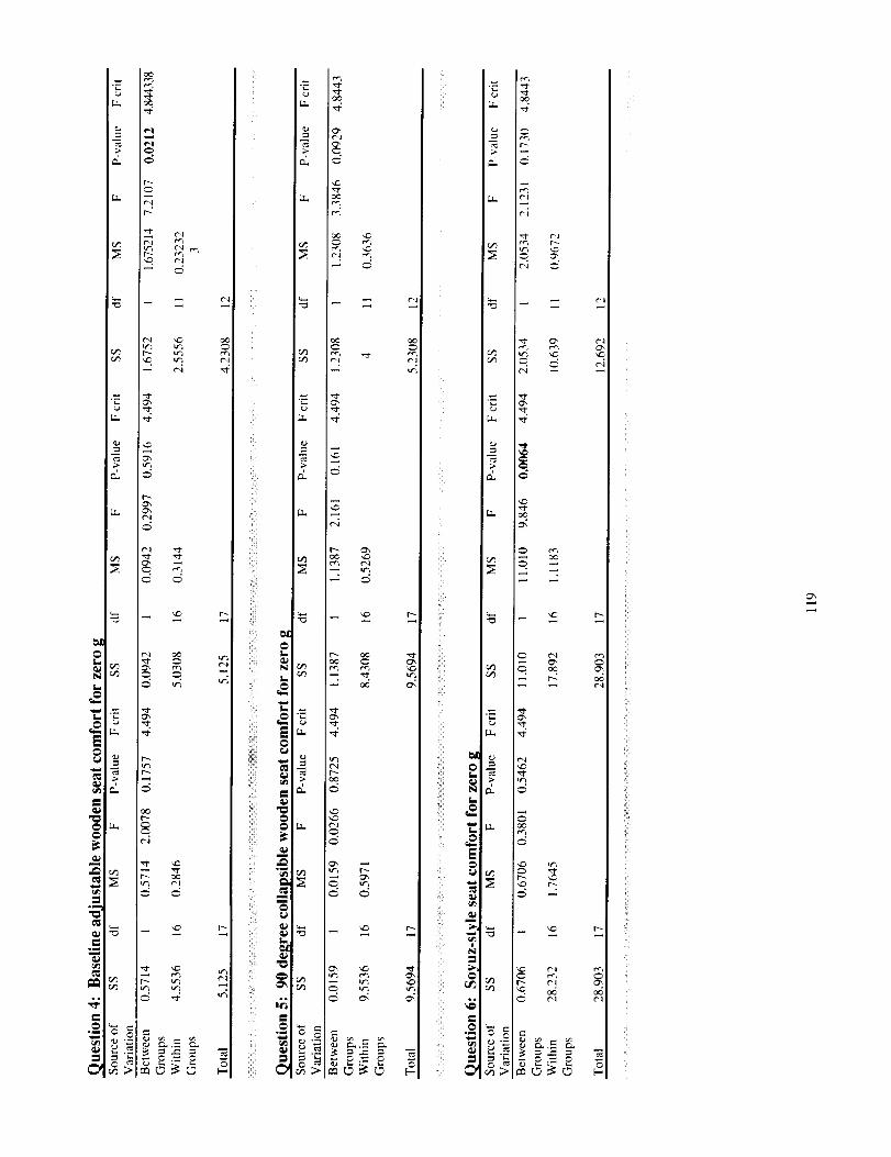
[..T. t.._l
t-.:
I.F+ t'+'l r+",f-++l'i
•-- _.
e_
I++d
N
_ •
t¢3 _-I
$1,_ -
+I_:ml+=:, = _.,_: }.-=..=_.=
tc"l
i'M
il
ii!i
iii_ii!ii_iiii_ii!i_iiiii!_i
@
i+++
ml+llml
o_,
ii m.i,, I
i_ _,.,+ i
iiii!ii_,+,.m,
ili!i!i__ _', I,m,
,ill
,,mI
.=
[..T..r+,-_r+.'-+
[.T... ,=1-
iz_.
.._ - ,,_
[..T...
[,..T.. ,t",l
C"-
tC_
u- i _
i!ii!_
i+ii:
_ +I¸+¸¸
@
+
Ir_
++}]+ ,_+++++ N
+ @++++++.
°=I
_. -'
e,%
-- "2.
r_
+++
+_+_=+
C+-,I
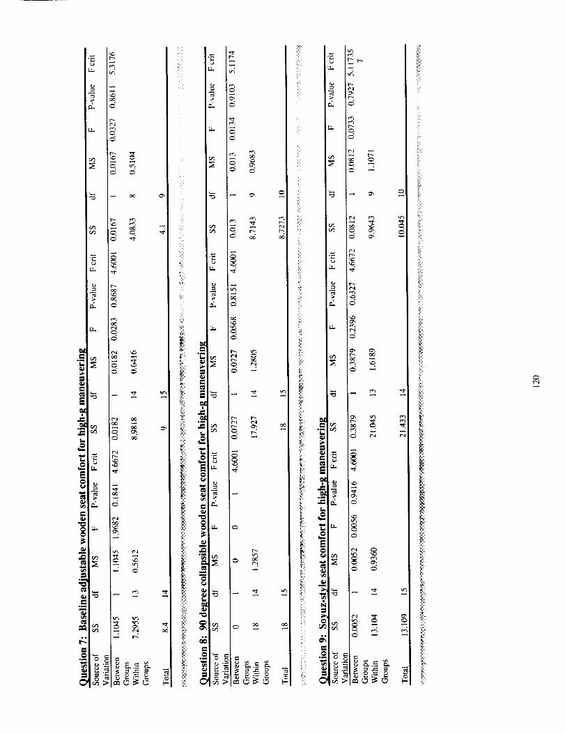
re_
.T_
o_
•_ r--
_I_LL _r
_i_'
_ t",l
_'_ _ _.._ _.
N°_ _,
i!_iI
il
_i̧ _
_ii̧ __
t_
"_ _ =
",::t
c6
t'_ I_t'l t_
r_r_
_._
t¢3
fM
iii!:i_
iii_iil
C
N L
N_
e _
u," gl/
m
i;i;ii:
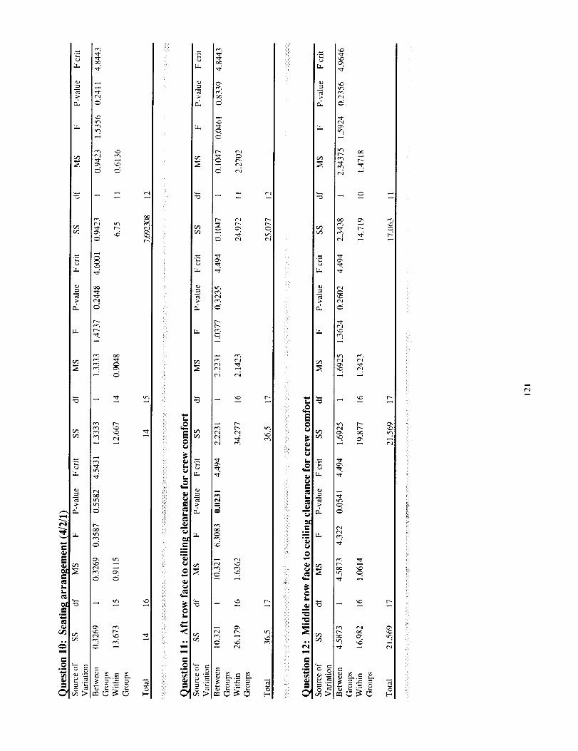
trl
eJ_
_ Qi9
_ r, _
o_
iil
;i
/i
iii
ii
4
lu
i.
Iiii Lm
i_¸ _i
iii!¸ _
ii!ii; _
F_
_ t",|
'T .._
t
t"-i
k
r_
i'
i:ii
f,ii,i
Ut_
!;!!_
iiii;;_i
i !!ii -<-
H,,
f.-
i.
i.
m
iiii!i;_
i{ °
ii!ii "_
LL
_ I_
t _
a _
12
ii!!_i;
!!_ix
;ii!i
_ ii!̧_
'i!
_-_ iii_
iii';
i;iil_
i i!!iq
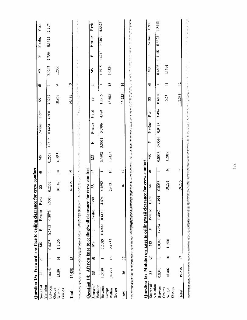
Lf_
i
_° _,_
Lr_
iii!i
LII
ill
I
iii_iili]
_ _!i_i_ii¸
Ii;
i!!i
II
r4_
_ r_
q_
i
i
i;
ill
ii_i!
flail
!i!_i
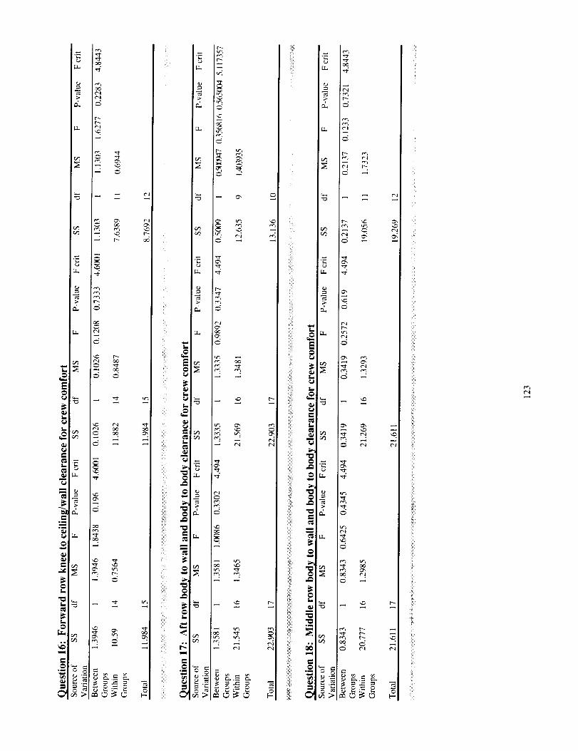
oc
!
[.,
°°
if!i! "-i!i!i
°_
!i_i¸
°li
!i,
i,
ii_!i
=:if*i!i ¸
L
ii_! ,.
°_
- _
_ _.--"N
_i_
iliil
i_!ili
t"',l
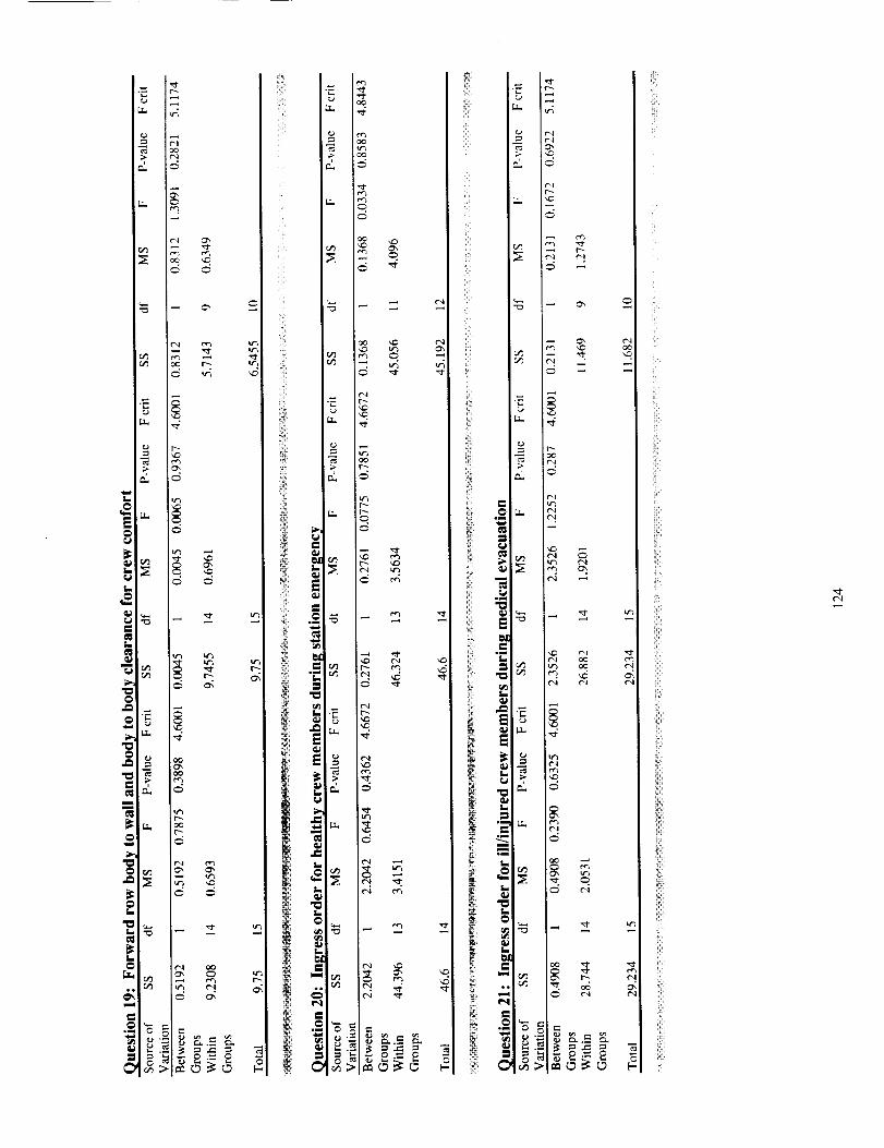
fJ rr_
0 _
Le_
?
_l _ - _
_0
L
[]
_i _mt
o_
L _
I_ ° _
iii!i_i
_m
o_
ii
ilil
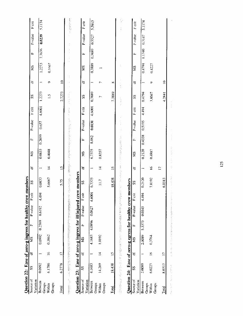
e,rD
_ r-- _
I-
I;
_ It',
4 _
°°u o¢_
I °
iiii--
r _
ill
i!
'!
)!;
i]i!i _
ii_!i_ I_
I.
_!ili=o_
_!ii_ ,_
ii]: t_
oml
ii? N
ii!! _
r_
i!i! _
ii:ii _
_ if',
rT a¢
J_d _
.,___ i_-.=-_
tr_
tr_
_d
i!
LP
iii lu
i!̧ _ii_i '-
f-
t_
I.
ii 11
N
_mii_: _
o_
ill =
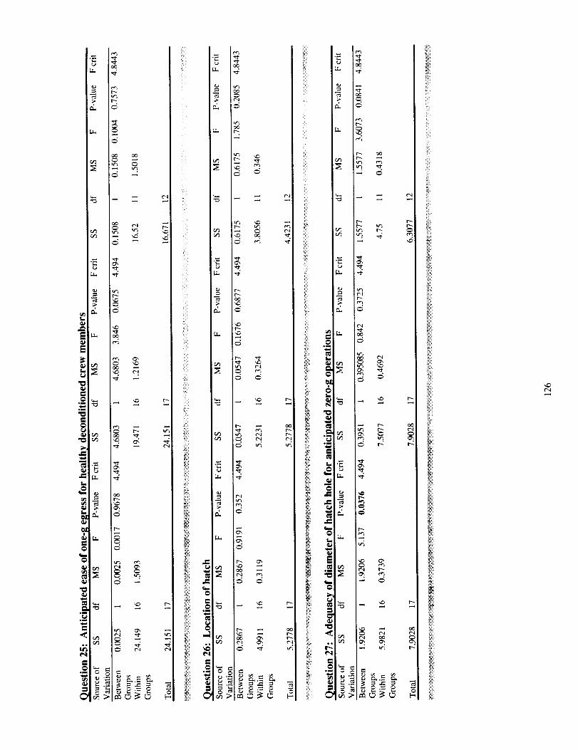
oc
L_ -4
E
Ii
_LLo
G",
I$
_4
c_
ii!_i
<i
2i<
!iiiiii
!!_ii!
iliii
ii'i
i!ii_
iii:_
ii_i!
iili
!!iiii:_
iKi
i
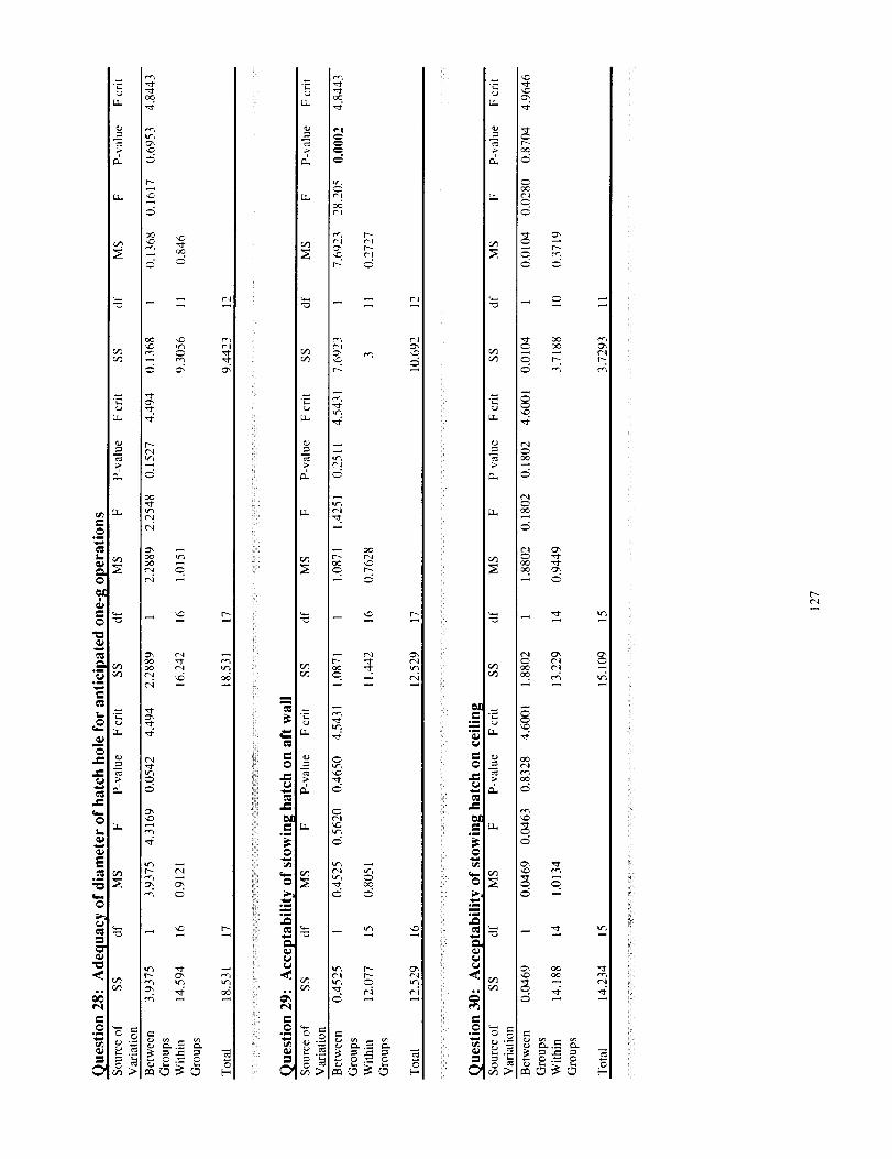
._o
c_
!ii̧ _
_ l_
L_
_I_ _
'i!
i!i_¸¸ _
t"
°I
ii¸ _
rT_
rT_ _
rl
LL
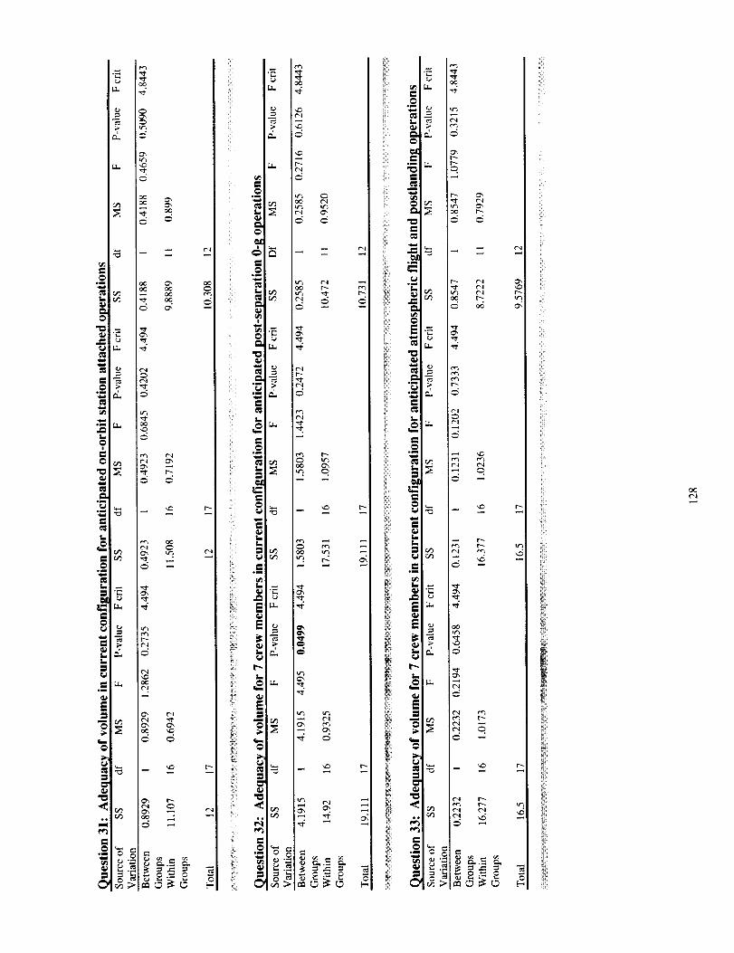
_1_ _c_Ii
°_ I__ __
iii_i
m_
L_
J_
L I
m_
q_
L_$
_ rv_
,d
g,
_ o,._
iliiilI
ii'_i
i_iiil
i!ii_
iii!i
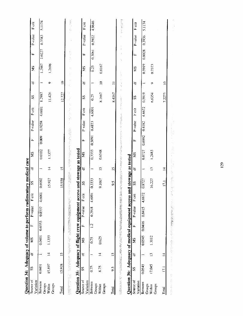
,?
i! ¸ _
i_ili¸¸ _
°_
rm
iiiiiiii_.
rT
Ct_
r_
('_
mr, i?_I_ r_
i!!i_!ii_il
i_i̧ _
_ _iI o
iil -_:
iii w,°_ _
_i̧_ _I
iiil___.
cx_
l_ rr;
m
r_
r_
!!ii
i i!i_i
i!iii_i
i_!!ii
ill_!_
iii:!_
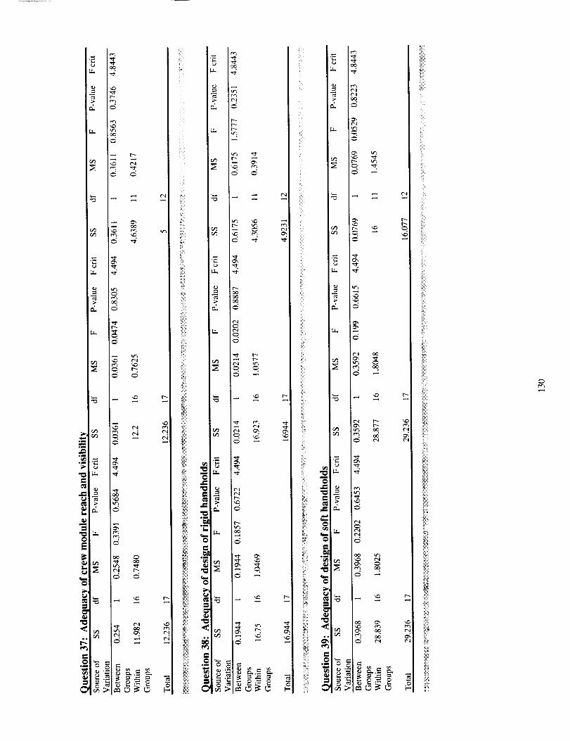
L _
q_E_
_
"c
i_i!!
r_
i_iiii_ _
ii! _
_!_i_ ._ _ _
°_•_ _
ii_!ill
_ i!! ¸
_C
El),._ rL
_J
M
.L,
ii_il
i!!i!,
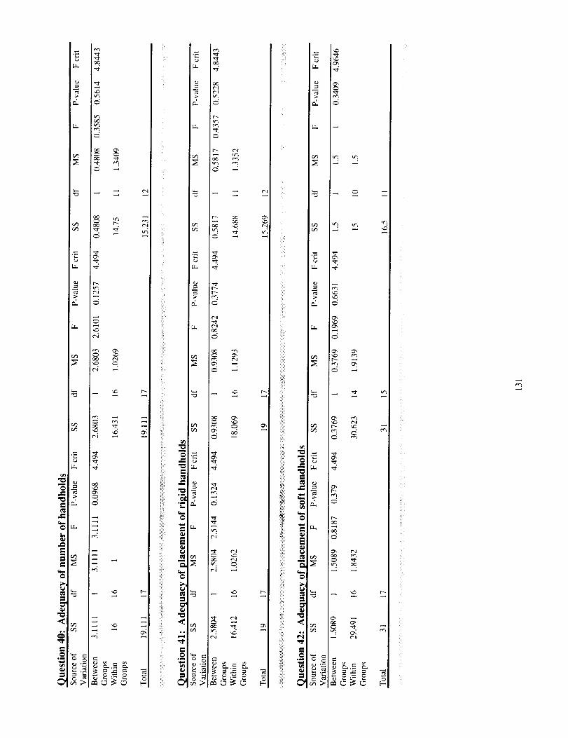
I++
I!++._+
"++
"0
__I+++
ill¸¸
,,,.-]
i/!
!_i "=
i!i +
=
m
_>,; @
:iiil =
t,-,
a. ,:/
e_
r_
I!-m d
e¢3
_ •
:2
:N
_ Nm o ,_t
_.-___
y
i/
i__Yl
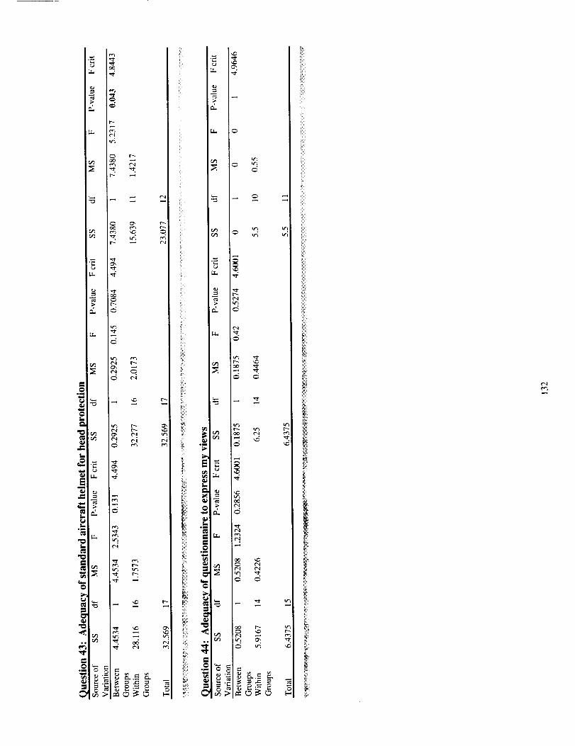
- !ii_
t _iii I
iiii
it
,$Lif"_
L.
c_
_Ju
q_
Com.qm
Lt,-,_
t_ if_w
8IJ °
_t
_H
IP
_t
_X
iI
er_
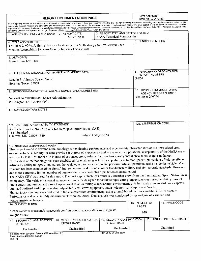
Form ApprovedREPORT DOCUMENTATION PAGE OMB No. 0704-0188
Public reporting burden for this collection of information is estimated to average I hour per responser including the time for revtewmg instructtons, searching existing data sources, gathenng andmaintaining the data needed, and completing and reviewing the collection of information Send comments regarding this burden estimate or any other aspect of this collection of information, including
suggestions for reducing this burden, to Washington Headquarters Services, Directorate for Information Operations and Reports, 1215 Jefferson Davis Highway, Suite 1204, Arlington, VA 22202-4302,and to the Office of Management and Budget, Paperwork Reduction Project (0704-0188), Washington, DC 20503
1. AGENCY USE ONLY (Leave Blank) 2. REPORT DATE 3. REPORT TYPE AND DATES COVEREDMarch 2000 NASA Technical Memorandmn
5. FUNDING NUMBERS4. TITLE AND SUBTITLETM-20(X)-209764, A Human Factors Evaluation of a Methodolog.v for Pressurized Crew
Module Acceptability for Zero-Gravity Ingress of Spacecraft
6. AUTHOR(S)
Merri J. Sanchez, PhD
7. PERFORMING ORGANIZATION NAME(S) AND ADDRESS(ES)
Lyndon B. Johnson Space Center
Houston, Texas 77058
9. SPONSORING/MONITORING AGENCY NAME(S) AND ADDRESS(ES)
National Aeronautics and Space Administration
Washington, DC 20546-(X)01
8. PERFORMING ORGANIZATIONREPORT NUMBERS
S-854
10. SPONSORING/MONITORINGAGENCY REPORT NUMBER
TM-2(X)O-2(_)764
11. SUPPLEMENTARY NOTES
12a. DISTRIBUTION/AVAILABILITY STATEMENT
Available from the NASA Center for AeroSpace Information (CASI)
7121 StandardHanover, MD 21076-1320 Subject Category: 54
12b. DISTRIBUTION CODE
13. ABSTRACT (Maximum 200 words)
This project aimed to develop a methodology for evaluating performance and acceptability characteristics of the pressurized crew
module volume suitability for zero-gravity (g) ingress of a spacecraft and to evaluate the operational acceptability of the NASA crew
return vehicle (CRV) for zero-g ingress of astronaut crew, volume for crew tasks, and general crew module and seat layout.
No standard or methodology has been established fl_r evaluating volume acceptability in human spaceflight vehicles. Volume affects
astronauts' ability to ingress and egress the vehicle, and to maneuver in and perform critical operational tasks inside the vehicle. Much
research has been conducted on aircraft ingress, egress, and rescue in order to establish military and civil aircraft standards. However,
due to the extremely limited number of human-rated spacecraft, this topic has been unaddressed.
The NASA CRV was used for this study. The prototype vehicle can return a 7-member crew from the International Space Station in an
emergency. The vehicle's internal arrangement must be designed to facilitate rapid zero-g ingress, zero-g maneuverability, ease of
one-g egress and rescue, and ease of operational tasks in multiple acceleration environments. A full-scale crew module mockup was
built and outfitted with representative adjustable seats, crew equipment, and a volumetrically equivalent hatch.
Human factors testing was conducted in three acceleration environments using ground-based facilities and the KC-135 aircraft.
Performance and acceptability measurements were collected. Data analysis was conducted using analysis of variance and
nonparametric techniques.
14. SUBJECT TERMS
escape systems: spacecraft; spacecraft configurations; spacecraft design; ingress;
weightlessness
17. SECURITY CLASSIFICATION 18. SECURITY CLASSIFICATIONOF REPORT OF THIS PAGE
Unclassified Unclassified
Standard Form 298 (Rev Feb 89) (MS Word Mar 97)
Prescribed by ANSI Std. 239-18298-102
15, NUMBER OF 16. PRICE CODEPAGES
140
19. SECURITY CLASSIFICATIONOF ABSTRACT
20. LIMITATION OF ABSTRACT
NSN 7540-01-280-5500
Unclassified Unlimited