A HIGH PERFORMANCE MEMS BASED DIGITAL-OUTPUT … HIGH PERFORM… · A HIGH PERFORMANCE MEMS BASED...
4
A HIGH PERFORMANCE MEMS BASED DIGITAL-OUTPUT GYROSCOPE A. Ismail, B. George, A. Elmallah, A. Mokhtar, M. Abdelazim , M. Elmala, A. Elshennawy, A. Omar, M. Saeed, I. Mostafa, A. Elsayed Si-ware Systems, Cairo, EGYPT ABSTRACT In this work, the architecture, and measurements results of an ultra-low noise closed-loop force feedback gyroscope, with superior bias instability, are presented. The MEMS is interfaced to a highly programmable capacitive interface ASIC, constructing a complete sensor module with a digital-output. Measurements results indicate the superior performance of the gyroscope, with a bias instability of 1°/hr, a noise floor of 1.3m˚/s/¥Hz, and a full-scale range of ±300°/s, while consuming 25mA from a 5V supply. KEYWORDS Gyroscopes, inertial sensors, Closed-loop sensors, force-feedback, electro-mechanical Ȉ-ǻ. INTRODUCTION The demand for high-performance micro-machined gyroscopes has grown, significantly, in the recent years, and MEMS gyroscopes have become an integral part of industrial instrumentation, avionics, and platform stabilization. While, the readout mechanism of micro-sensors can be of piezoelectric, piezoresistive or capacitive nature, the high thermal stability, and high sensitivity of capacitive sensing makes it more suited for high performance applications. A typical capacitive gyro interface circuit is composed of a capacitance-to-voltage converter (C/V) followed by an analog-to-digital converter (ADC) and signal conditioning circuitry. It was shown, previously [1][2], that incorporating the sensor and C/V in a Ȉ-ǻ based force-feedback loop provides many benefits, such as reducing sensitivity to sensor process and temperature variation, improving system bandwidth, and increasing dynamic range. To overcome the non-linearity of the voltage-to-force (V/F) relation in capacitive feedback, a two-level feedback signal is required. Since, only two points of the quadratic V/F relation are exercised, this approach is inherently linear. Therefore, single-bit Ȉ-ǻ modulation represents a practical way to implement capacitive sensors interface circuits. It should be noted that the oversampling nature of Ȉ- ǻ systems imposes operating system at relatively high frequencies, and hence, system becomes more susceptible to coupling through the MEMS parasitic capacitances. Nonetheless, circuit techniques to cancel this coupling are possible, and were implemented in the interface ASIC of the presented sensor. The following sections reveal the architecture and implementation details of a high performance, force- feedback, digital-readout gyroscope. The measurement results of the gyroscope are also presented. GYROSCOPE ARCHITECTURE The system architecture of the gyroscope is shown in Fig.1. The gyro interface ASIC provides the actuation voltages for the sense and drive sensor electrodes, and the proof mass excitation voltage signal required by the capacitance sensing circuit. The MEMS together with the ASIC construct the oscillatory drive loop, and the sense loop required for closed-loop operation. The MEMS capacitances variations of the sense and drive resonators are detected by the capacitance-to- voltage converters (C/V). The C/V interface is built as a switched-capacitor discrete-time circuit. An input common-mode feed-back loop is implemented to eliminate the common-mode component resulting from the common-mode excitation [3]. Two programmable capacitor arrays are used to remove the offset of the differential MEMS capacitors. The C/V is composed of two stages of amplification, and employs chopping technique to remove the low frequency noise and offset of both first and second stages. The capacitance-to-voltage converters (C/V) of the drive and sense loops share some of their circuitry, allowing considerable power saving. The C/V’s are followed by two ADC’s that digitize the detected drive and sense signals. Hence, the drive and sense loops are implemented in the digital domain. Digital implementation of the sense and drive loops permits a high-level of programmability for loops coefficients and parameters, compared to analog realization [4]. The two ADC’s of the drive and sense loop are identical and share the same reference voltage buffer to save power. The power dissipation of the two ADC’s is negligible compared to the power dissipation of the C/V’s. Thus digital realization of the drive and sense loops comes at no significant penalty in sensor overall power dissipation. A phase-locked loop (PLL) is used to generate the system clock. The high Q resonance of the gyro oscillation is used to generate a clean reference clock for the ASIC PLL, resulting in minimum noise floor at the ASIC output. This is realized by incorporating a sample and hold circuit after the drive mode C/V. The sample and hold circuit is followed by a continuous time filter, and a differential-to-CMOS converter to generate the reference signal of the PLL. Hence, the ASIC PLL does not need an external crystal as a reference clock, and the ASIC becomes self-clocked [4]. Using a gyro based reference clock allows fixing the ratio between the system sampling frequency and the mechanical drive resonance frequency (Coriolis signal carrier). Therefore, self-clocking scheme, combined with the high programmability of the digital sense and drive loops, enable ASIC interfacing to a wide- range of MEMS gyro modules. The power management section comprises a low noise band-gap circuit (BGC) that generates a 1.2V reference voltage. The reference voltage is used by power- Th1A.003 978-1-4673-5983-2/13/$31.00 ©2013 IEEE 2523 Transducers 2013, Barcelona, SPAIN, 16-20 June 2013
Transcript of A HIGH PERFORMANCE MEMS BASED DIGITAL-OUTPUT … HIGH PERFORM… · A HIGH PERFORMANCE MEMS BASED...
A HIGH PERFORMANCE MEMS BASED DIGITAL-OUTPUT GYROSCOPE
A. Ismail, B. George, A. Elmallah, A. Mokhtar, M. Abdelazim , M. Elmala, A. Elshennawy, A. Omar, M. Saeed, I. Mostafa, A. Elsayed Si-ware Systems, Cairo, EGYPT
ABSTRACT
In this work, the architecture, and measurements results of an ultra-low noise closed-loop force feedback gyroscope, with superior bias instability, are presented. The MEMS is interfaced to a highly programmable capacitive interface ASIC, constructing a complete sensor module with a digital-output. Measurements results indicate the superior performance of the gyroscope, with a bias instability of 1°/hr, a noise floor of 1.3m˚/s/¥Hz, and a full-scale range of ±300°/s, while consuming 25mA from a 5V supply. KEYWORDS
Gyroscopes, inertial sensors, Closed-loop sensors, force-feedback, electro-mechanical Ȉ-ǻ. INTRODUCTION
The demand for high-performance micro-machined gyroscopes has grown, significantly, in the recent years, and MEMS gyroscopes have become an integral part of industrial instrumentation, avionics, and platform stabilization.
While, the readout mechanism of micro-sensors can be of piezoelectric, piezoresistive or capacitive nature, the high thermal stability, and high sensitivity of capacitive sensing makes it more suited for high performance applications.
A typical capacitive gyro interface circuit is composed of a capacitance-to-voltage converter (C/V) followed by an analog-to-digital converter (ADC) and signal conditioning circuitry. It was shown, previously [1][2], that incorporating the sensor and C/V in a Ȉ-ǻ based force-feedback loop provides many benefits, such as reducing sensitivity to sensor process and temperature variation, improving system bandwidth, and increasing dynamic range. To overcome the non-linearity of the voltage-to-force (V/F) relation in capacitive feedback, a two-level feedback signal is required. Since, only two points of the quadratic V/F relation are exercised, this approach is inherently linear. Therefore, single-bit Ȉ-ǻ modulation represents a practical way to implement capacitive sensors interface circuits.
It should be noted that the oversampling nature of Ȉ-ǻ systems imposes operating system at relatively high frequencies, and hence, system becomes more susceptible to coupling through the MEMS parasitic capacitances. Nonetheless, circuit techniques to cancel this coupling are possible, and were implemented in the interface ASIC of the presented sensor.
The following sections reveal the architecture and implementation details of a high performance, force-feedback, digital-readout gyroscope. The measurement results of the gyroscope are also presented.
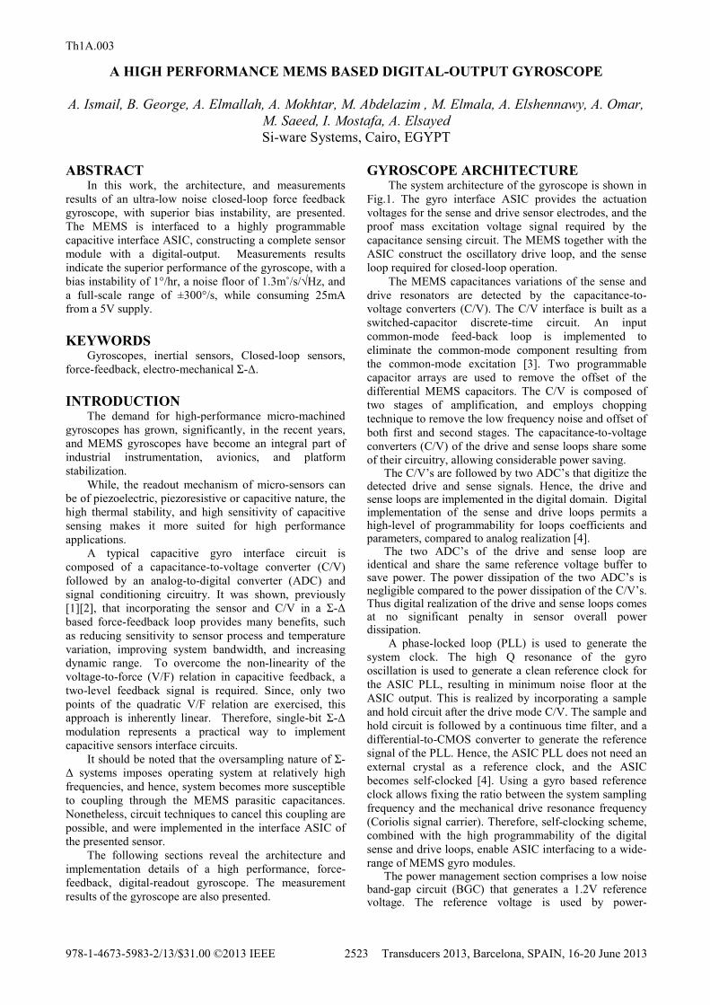
GYROSCOPE ARCHITECTURE The system architecture of the gyroscope is shown in
Fig.1. The gyro interface ASIC provides the actuation voltages for the sense and drive sensor electrodes, and the proof mass excitation voltage signal required by the capacitance sensing circuit. The MEMS together with the ASIC construct the oscillatory drive loop, and the sense loop required for closed-loop operation.
The MEMS capacitances variations of the sense and drive resonators are detected by the capacitance-to-voltage converters (C/V). The C/V interface is built as a switched-capacitor discrete-time circuit. An input common-mode feed-back loop is implemented to eliminate the common-mode component resulting from the common-mode excitation [3]. Two programmable capacitor arrays are used to remove the offset of the differential MEMS capacitors. The C/V is composed of two stages of amplification, and employs chopping technique to remove the low frequency noise and offset of both first and second stages. The capacitance-to-voltage converters (C/V) of the drive and sense loops share some of their circuitry, allowing considerable power saving.
The C/V’s are followed by two ADC’s that digitize the detected drive and sense signals. Hence, the drive and sense loops are implemented in the digital domain. Digital implementation of the sense and drive loops permits a high-level of programmability for loops coefficients and parameters, compared to analog realization [4].
The two ADC’s of the drive and sense loop are identical and share the same reference voltage buffer to save power. The power dissipation of the two ADC’s is negligible compared to the power dissipation of the C/V’s. Thus digital realization of the drive and sense loops comes at no significant penalty in sensor overall power dissipation.
A phase-locked loop (PLL) is used to generate the system clock. The high Q resonance of the gyro oscillation is used to generate a clean reference clock for the ASIC PLL, resulting in minimum noise floor at the ASIC output. This is realized by incorporating a sample and hold circuit after the drive mode C/V. The sample and hold circuit is followed by a continuous time filter, and a differential-to-CMOS converter to generate the reference signal of the PLL. Hence, the ASIC PLL does not need an external crystal as a reference clock, and the ASIC becomes self-clocked [4]. Using a gyro based reference clock allows fixing the ratio between the system sampling frequency and the mechanical drive resonance frequency (Coriolis signal carrier). Therefore, self-clocking scheme, combined with the high programmability of the digital sense and drive loops, enable ASIC interfacing to a wide-range of MEMS gyro modules.
The power management section comprises a low noise band-gap circuit (BGC) that generates a 1.2V reference voltage. The reference voltage is used by power-
Th1A.003
978-1-4673-5983-2/13/$31.00 ©2013 IEEE 2523 Transducers 2013, Barcelona, SPAIN, 16-20 June 2013
management regulators and other bias cores. In addition, the BGC supplies a buffered version of the reference voltage to the sense and drive loop ADC’s, in addition to the excitation/actuation switches and the temperature sensor.
An integrated voltage charge-pump doubles the system supply voltage and produces necessary high-voltage (HV). The high-voltage is used for excitation, actuation. In addition, the HV is utilized for improving gyro startup time.
The voltage levels of both the actuation and excitation signals are programmable, which provide the interface ASIC with the necessary flexibility to work with different MEMS designs, while providing optimized performance.
THE DRIVE LOOP
The drive signal is processed in the digital domain.
The drive-loop includes the phase shift required to achieve the oscillation condition, as well as, automatic gain control (AGC) block to control the amplitude of oscillation of the mechanical element. The drive loop includes, also, programmable band-pass digital filters. These filters are automatically tuned to the drive frequency through their sampling frequency, due to the self-clocking feature. THE SENSE LOOP
Capacitive inertial MEMS sensors exhibit a second order low-pass transfer function. In [1], the MEMS serves as the Ȉ-ǻ loop filter, resulting in a 2nd order electro-mechanical Ȉ-ǻ loop. However, relying only on the MEMS, as the filtering element, results in a resolution penalty, due to increased quantization noise.
Figure 1: MEMs Gyro/ASIC system architecture.
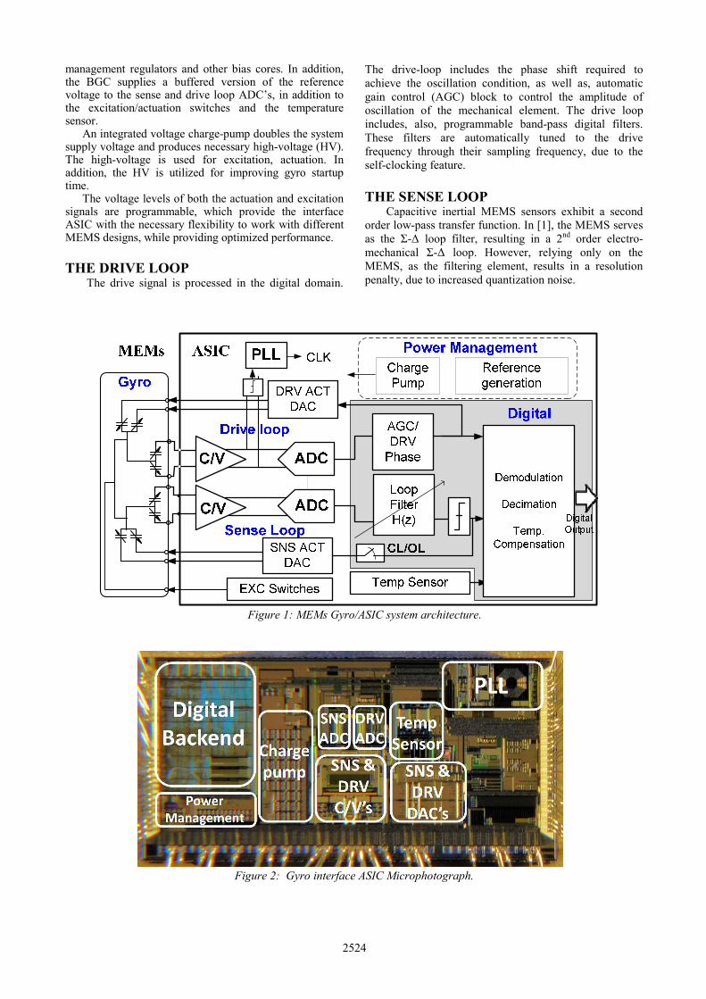
Figure 2: Gyro interface ASIC Microphotograph.
2524

The increased quantization noise results from the reduced effective Ȉ-ǻ loop quantizer gain, caused by electronic noise [5]. To avoid resolution penalty an additional electronic filter is introduced to the loop. The additional electronic filter can be of first or second order for accelerometer sensors, but for gyroscopes a second order filter is used to implement a resonator that can produce a notch in the noise transfer function away from DC, resulting in a 4th order modulator [2] [6]. The gyro sense-loop, of this work, is formed of a 4th order electro-mechanical ǻȈ modulator, with the electronic loop filter implemented as a digital filter.
The sense-loop is designed to allow open-loop mode of operation, where the feedback signal is disconnected and the sense loop ADC provides digital readout for the sensor input. DIGITAL PROCESSING AND TEMPERATURE COMPENSATION
The digital processing backend filters the output of the ǻȈ modulators of the drive and sense loops, and performs output demodulation. The demodulation output is decimated using a programmable decimation filter. The decimation filter is composed of a cascaded-integrator comb (CIC) filter, followed by a half band filter, and finally a droop correction filter is used to compensate the non-flat frequency response of the CIC filter.
The sense output signal is filtered before demodulation to avoid down conversion of quantization noise in the band of interest. The filter poles and zeros scale with the sampling frequency (which tracks the MEMS drive frequency). Therefore the filter is correctly tuned with variations of the gyro resonance frequency.
The temperature sensing system measures the die temperature and converts it into a digital reading, which is used for temperature compensation of the scale factor and the zero-rate output (ZRO) of the gyro reading. Temperature sensing is performed via a PTAT sensor. A first order incremental ǻȈ ADC, consisting of a switched capacitor integrator and a comparator, digitizes the sensor’s output providing a digital representation of the temperature. The switched capacitor integrator provides the required scaling and shifting of the sensor’s output to be centered within the dynamic range of the temperature sensor ADC. IMPLEMENTATION AND MEASUREMENTS
The gyroscope ASIC microphotograph is depicted in Fig.2. The ASIC is fabricated in 0.18ȝm HVCMOS technology featured with 10V LDMOS devices and occupies an area of 12mm2. In Fig. 3, the measured output spectrum of the Ȉ-ǻ sense-loop is shown. The ASIC was tested with a MEMS sensing element supplied by Tronics Microsystems. The resonance frequency of the sensing element is 3.4 kHz.
The measured DC transfer charachteristics of the gyrosope is presented in Fig. 4. The full-scale signal is ±300°/s .The maximum Linearity error measured = 0.007 % of full-scale (FS).
The measured gyroscope bias instability (Allan
variance) is 1°/hr. The noise floor measurement and zero-rate output drift with temperature with/without compensation are shown in Fig. 5, and Fig. 6, respectively. The gyroscope achieves a noise floor of 1.3m°/s/¥Hz, over a bandwidth (BW) of 100Hz, and a thermal bias stability of ±0.05°/s. The gyroscope performance is summarized in Table 1.
CONCLUSIONS
A high performance gyroscope, with superior bias instability of 1°/hr, a ±300°/s input range, and a 100Hz BW, is presented. The sensors employs a highly configurable interface ASIC. The ASIC sense and drive loops processing is implemented in the digital domain, providing a high-level of programmability for loops coefficients and parameters, compared to analog realization. The digital realization of the loops, combined with the self-clocking feature, and the programmability of the actuation and excitation signals voltage levels allow the ASIC to interface to a wide-range of MEMS gyro modules. ACKNOWLEDGEMENTS
The authors would like to thank A. Khalifa, for conducting measurements required for this publication, A. Oweis for testing board design, and C. Kergueris at Tronics Microsystems for providing the MEMS parts.
Figure3: Measured output spectrum of the Ȉ-ǻ sense loop showing quadrature signal and noise shaping.
Figure4: Measured DC transfer characteristics (normalized output digital reading vs. input angular velocity). Maximum Linearity error measured = 0.007 %FS
2525

Figure 5: Gyroscope output reading, indicating noise floor of 1.3m˚/s/¥Hz (BW=100Hz).
Figure 6:Zero-rate output vs. temperature with and without temperature compensation.
Table 1: System parameters and measured performance.
ASIC Process technology 0.18µm 2P6M HVCMOS
ASIC area (mm2) 12 (5mmX2.4mm) Supply voltage (V) 5 Total Sensor supply current (mA)
25
Full scale signal (°/s) ±300 Noise Floor (°/s/¥Hz) 1.3m Bias instability (Allan variance) (°/hr)
1
Thermal bias stability (°/s) ±0.05 DC Linearity (%Full scale) 0.007 BW (Hz) 100 Startup time (s) 1
REFERENCES [1] M. Lemkin and B. Boser, “A Three- Axis
Micromachined Accelerometer with a CMOS Position-Sense Interface and Digital Offset-Trim Electronics,” IEEE J. Solid-State Circuits, vol. 34, no. 4, pp. 456–468, Apr. 1999.
[2] V. P. Petkov, , and B. Boser, “A Fourth-order Ȉ-ǻ Interface for Micromachined Intertial sensors,” IEEE J. Solid-State Circuits, vol. 40, no. 8, pp. 1602–1609, Aug. 2005.
[3] X. Jiang, J. Seeger, M. Kraft, and B. Boser, “A Monolithic Surface Micromachined Z-Axis Gyroscope with Digital Output,” Dig. Symp. VLSI Circuits, pp. 16-19, June 2000.
[4] A. Elsayed, A. Elshennawy, A. Elmallah, A. Shaban, B. George, M. Elmala, A. Ismail, A. Wassal, M. Sakr, A. Mokhtar, M. Hafez, A. Hamed, M. Saeed, M. Samir, M. Hammad, M. Elkhouly, A. Kamal, M. Rabieah, A. Elghufaili, S. Shaibani, I. Hakami, T. Alanazi, "A Self-Clocked ASIC Interface for MEMS Gyroscope with 1m°/s/¥Hz Noise Floor," in Proc. IEEE Custom Integrated Circuits Conf. Dig. Tech. Papers, 2011.
[5] V. P. Petkov, , and B. Boser,, “High-order Electromichanical Ȉ-ǻ Modulation in Micromachined Intertial sensors,” IEEE Trans. Circuits Syst. I, vol. 53, no. 5, pp. 1016–1022, May 2006.
[6] J. Raman, P. Rombouts, and L. Weyten, “An Unconstrained Architecture for Systematic Design of Higher Order Ȉ-ǻ Force Feedback Loops,” IEEE Trans. Circuits Syst. I, vol. 55, no. 6, pp. 1601–1614, July 2008.
CONTACT
*A. Ismail, tel: +20-111-3207772; [email protected]
2526