A Hierarchy of Neuromechanical and Robotic … Hierarchy of Neuromechanical and Robotic Models of...
7
A Hierarchy of Neuromechanical and Robotic Models of Antenna-Based Wall Following in Cockroaches Jusuk Lee, Owen Y. Loh and Noah J. Cowan Abstract— It may come as no surprise that a simple “planar unicycle” (or “skate”) model can successfully follow a wall at high speed under PD-control. What would be surprising is that such a simple control mechanism may underly the control of one of Nature’s fastest terrestrial insects, the American cockroach. For this paper, we implemented the same controller (up to scale) believed to govern cockroach wall following to successfully control two models of the cockroach: a differential- drive mobile robot with a flexible artificial antenna and a lateral leg spring model with moving center of pressure as the control input. These physical and numerical experiments demonstrate the sufficiency of the cockroach’s putative controller in a real- world setting with unmodeled effects, and suggest how the nervous system might guide leg placement in response to sensory stimuli. This hierarchy of models may prove useful in generating prescriptive hypotheses for biological testing and hence elucidating the general principles that underly sensor- guided animal locomotion. I. I NTRODUCTION American cockroaches (Periplaneta americana) can run up to 1.5 m/s (or 50 body lengths/s), even changing their gait to bipedal in order to achieve high speeds [9]. When they encounter a wall, they typically run along it using their antenna to regulate their distance from the wall. They are capable of tracking a zigzagged wall of up to 25 turns/s [3]. Biologists and engineers alike are interested in understand- ing the fundamental mechanisms that underlie such agility. Specifically, we are interested in how cockroaches process sensory data from their antenna for control of locomotion. One approach to this problem has been a bottom-up approach: fit kinematic data to a synaptically-interconnected gross neural network model of biologically-relevant neurons. Chapman and Webb [5] implemented such a neural circuit on a mobile robot where IR sensors were used as the robot’s “antenna”; their robot exhibited an escape response followed by a wall-following response, much like that of a cockroach. However, the sheer complexity of the neural network hampers any formal mathematical analysis (e.g., stability analysis) on their neural controller. In addition, the absence of the robot’s mechanical parameters (e.g., body mass and inertia) in the overall modeling process may produce synaptic weights that may not reflect the animal’s actual neural controller [6]. In this paper, we use an alternative, top-down approach: find the simplest control law (in the classical control theory O. Loh was supported by a JHU Provosts Undergraduate Research Award. J. Lee and N. Cowan are with the Mechanical Engineering De- partment at Johns Hopkins University, Baltimore, MD 21218 USA. {jsl,ncowan}@jhu.edu O. Loh is with the Mechanical Engineering Department at Northwestern University, Evanston, IL 60208 USA. [email protected] sense) that abstractly models the cockroach’s neural con- troller. This approach elucidates the general functions of the neural network as a whole, allowing one to predict how actual neural signals may look [6], [7]. Of course, the models we present in this paper are behavior specific, and thus do not capture the complex dynamics—such as switching between escape response and wall following—that may emerge out of more elaborated neural-network-based models [5]. We utilize the notion of templates and anchors [8] to sys- tematically formulate the synthesis of sensory, body, and neu- ral controller dynamics; such formulation makes the model amenable to formal mathematical analyses. A template is the simplest model that captures a specific behavior, while an anchor is a more complex, representative model of the behavior. Templates and anchors are not just “simple models” and “complex models”; there must be a natural embedding of the template behavior within the anchor [8]. For example, horizontal plane locomotion in sprawled-posture animals, such as many insects, is well characterized by the lateral leg-spring (LLS) template because the animal’s center of mass (COM) bounces side-to-side [23]–[25]. In this paper, we consider multiple levels in a template-anchor hierarchy (shown in Fig. 1) and show (1) how they are “connected” to each other and (2) biological predictions one can generate from each level in the hierarchy. In Section II, we briefly review the simplest template for high-speed wall following proposed by Cowan et al. [7]: antenna-based planar unicycle (APU) (see Fig. 1). Using classical control theory, they show that P-control is not sufficient for stable wall following. For their experiments the next simplest control law, PD-control, most parsimoniously accounts for the data. In Section III, we consider one anchor for the APU model: our mobile robot with an artificial antenna (see Fig. 1). We first discuss the design of the antenna as well as its construction. Then we show the analytical embedding of the APU model in the Garcia robot model. Using the principle of similitude, we map the best-fit parameters from the cockroach ethological experiments to the robot’s parameters and control gains; the robot exhibits stability without any parameter tuning. The success of our trials demonstrates the sufficiency of the PD-controller in a real-world setting with unmodeled effects including a flexible antenna and its friction with the wall. In addition, our result supports Camhi and Johnson’s [3] claim that the sensors at the base of the cockroach antenna may not be necessary in the high-speed wall following. In Section IV, we consider another anchor for the APU
Transcript of A Hierarchy of Neuromechanical and Robotic … Hierarchy of Neuromechanical and Robotic Models of...

A Hierarchy of Neuromechanical and Robotic Models ofAntenna-Based Wall Following in Cockroaches
Jusuk Lee, Owen Y. Loh and Noah J. Cowan
Abstract— It may come as no surprise that a simple “planarunicycle” (or “skate”) model can successfully follow a wall athigh speed under PD-control. What would be surprising is thatsuch a simple control mechanism may underly the controlof one of Nature’s fastest terrestrial insects, the Americancockroach. For this paper, we implemented the same controller(up to scale) believed to govern cockroach wall following tosuccessfully control two models of the cockroach: a differential-drive mobile robot with a flexible artificial antenna and a lateralleg spring model with moving center of pressure as the controlinput. These physical and numerical experiments demonstratethe sufficiency of the cockroach’s putative controller in a real-world setting with unmodeled effects, and suggest how thenervous system might guide leg placement in response tosensory stimuli. This hierarchy of models may prove usefulin generating prescriptive hypotheses for biological testing andhence elucidating the general principles that underly sensor-guided animal locomotion.
I. INTRODUCTION
American cockroaches (Periplaneta americana) can runup to 1.5 m/s (or 50 body lengths/s), even changing theirgait to bipedal in order to achieve high speeds [9]. Whenthey encounter a wall, they typically run along it using theirantenna to regulate their distance from the wall. They arecapable of tracking a zigzagged wall of up to 25 turns/s [3].Biologists and engineers alike are interested in understand-ing the fundamental mechanisms that underlie such agility.Specifically, we are interested in how cockroaches processsensory data from their antenna for control of locomotion.
One approach to this problem has been a bottom-upapproach: fit kinematic data to a synaptically-interconnectedgross neural network model of biologically-relevant neurons.Chapman and Webb [5] implemented such a neural circuiton a mobile robot where IR sensors were used as therobot’s “antenna”; their robot exhibited an escape responsefollowed by a wall-following response, much like that ofa cockroach. However, the sheer complexity of the neuralnetwork hampers any formal mathematical analysis (e.g.,stability analysis) on their neural controller. In addition, theabsence of the robot’s mechanical parameters (e.g., bodymass and inertia) in the overall modeling process mayproduce synaptic weights that may not reflect the animal’sactual neural controller [6].
In this paper, we use an alternative, top-down approach:find the simplest control law (in the classical control theory
O. Loh was supported by a JHU Provosts Undergraduate Research Award.J. Lee and N. Cowan are with the Mechanical Engineering De-
partment at Johns Hopkins University, Baltimore, MD 21218 USA.{jsl,ncowan}@jhu.edu
O. Loh is with the Mechanical Engineering Department at NorthwesternUniversity, Evanston, IL 60208 USA. [email protected]
sense) that abstractly models the cockroach’s neural con-troller. This approach elucidates the general functions of theneural network as a whole, allowing one to predict howactual neural signals may look [6], [7]. Of course, the modelswe present in this paper are behavior specific, and thus do notcapture the complex dynamics—such as switching betweenescape response and wall following—that may emerge outof more elaborated neural-network-based models [5].
We utilize the notion of templates and anchors [8] to sys-tematically formulate the synthesis of sensory, body, and neu-ral controller dynamics; such formulation makes the modelamenable to formal mathematical analyses. A template isthe simplest model that captures a specific behavior, whilean anchor is a more complex, representative model of thebehavior. Templates and anchors are not just “simple models”and “complex models”; there must be a natural embeddingof the template behavior within the anchor [8]. For example,horizontal plane locomotion in sprawled-posture animals,such as many insects, is well characterized by the lateralleg-spring (LLS) template because the animal’s center ofmass (COM) bounces side-to-side [23]–[25]. In this paper,we consider multiple levels in a template-anchor hierarchy(shown in Fig. 1) and show (1) how they are “connected” toeach other and (2) biological predictions one can generatefrom each level in the hierarchy.
In Section II, we briefly review the simplest template forhigh-speed wall following proposed by Cowan et al. [7]:antenna-based planar unicycle (APU) (see Fig. 1). Usingclassical control theory, they show that P-control is notsufficient for stable wall following. For their experiments thenext simplest control law, PD-control, most parsimoniouslyaccounts for the data.
In Section III, we consider one anchor for the APU model:our mobile robot with an artificial antenna (see Fig. 1).We first discuss the design of the antenna as well as itsconstruction. Then we show the analytical embedding of theAPU model in the Garcia robot model. Using the principleof similitude, we map the best-fit parameters from thecockroach ethological experiments to the robot’s parametersand control gains; the robot exhibits stability without anyparameter tuning. The success of our trials demonstratesthe sufficiency of the PD-controller in a real-world settingwith unmodeled effects including a flexible antenna and itsfriction with the wall. In addition, our result supports Camhiand Johnson’s [3] claim that the sensors at the base of thecockroach antenna may not be necessary in the high-speedwall following.
In Section IV, we consider another anchor for the APU

anchortemplate
simple complex
Mathematical Models
Physical Systems
Garcia RHex
APU ALLS SimSect
Fig. 1. Our research program involves multiple levels of modeling, robotic experimentation, ethology, and neurophysiology. In this paper, we present asequence of antenna-based wall following models of increasing complexity, and at each stage make predictions about both robot and biological performance.Here, we present three models: the APU (Section II), a model for our Garcia robot (Section III), and the antenna-based LLS (ALLS) (Section IV). Importantly,each level of modeling admits the same control structure, including parameters (up to scale). The two physical systems involved in this study are the Garciarobot and an actual American cockroach. Eventually, we plan to extend our modeling effort to more elaborated anchors, such as the planar, multi-leggedmodel proposed by Seipel et al. [28], or the spatial SimSect model developed by Saranli et al. [20] of RHex [21]. As well, we plan to extend ourexperimental robotics work to include a RHex-like six legged robot, endowed with an artificial antenna.
model: antenna-based lateral leg spring (ALLS) model (seeFig. 1). Here we also show, numerically but not formally, theembedding of the APU model within the ALLS. From this,we ask how might such a simple control mechanism, namelyPD-control with an antenna, be implemented on a leggedmechanism? We show that antenna-based feedback-drivenplacement of the center of pressure (COP) of the LLS modelenables us to control the LLS to follow along a wall usinga virtual antenna, with no modification of the control gainsused for the lower-dimensional template model. This analysissuggests new biological experiments, and should lead to newcontrol strategies for legged robots such as RHex [1], [21],Sprawl [4], or Whegs [19].
II. REVIEW: ANTENNA-BASED PLANAR UNICYCLE(APU)
In this section, we briefly review the mathematical setupby Cowan et al. [7]. They modeled the high-speed wallfollowing of P. americana as a planar unicycle with polarmoment of inertia, and the antenna is assumed to measure d(see Fig. 2) where d = ` tan θ + y sec θ.
Cowan et al. proposed the PD-control law shown in Fig. 3.This yields the closed-loop model:
y = v∗ sin θ,
θ = ω,
ω = −αω−KP (d− d∗)−KDd︸ ︷︷ ︸u
, (1)
where α = B/J , J is polar moment of inertia, B is dampingcoefficient, and u is the inertia-scaled polar moment that thecockroach must generate in order to turn [11]. They obtainedparameters (`, α, KP , KD) by fitting (1) to biological high-speed wall-following data; their fitted parameter values aregiven in Table I (first row). Using classical control theory,Cowan et al. showed that P-control is not sufficient for stablewall following and that the next simplest control law, PD-control, most parsimoniously accounts for the data.
dv
+
Y
X
A B
*
Fig. 2. (Adapted from [7]) (A) Depiction of a cockroach following astraight wall. (B) Unicycle model of the running cockroach: ` is the look-ahead distance; d is the antenna measurement; v∗ is the forward runningspeed which is assumed to be constant; θ, is the angle of the cockroachbody relative to the wall (note that θ < 0 in this figure).
+ -s+ vs
1s2 + αs
KP + KDs
Neural controller Mechanics Antenna
d d
u* *
Fig. 3. (From [7]) Block diagram of simplified control model. The“mechanics” box represents the torsional dynamics. The “sensing” box is asimplified model of the antenna sensing kinematics. Cowan et al. [7] fit asimplified neural controller (in the dashed box) to their experimental data;d∗ is a nominal “desired” wall-following distance.
III. ARTIFICIAL ANTENNA AND DIFFERENTIAL-DRIVEROBOT
In this section, we use a mobile robot (Garcia, Fig. 5)as a test platform to support the efficacy of using theAPU as a template model for the high-speed wall-followingcockroach; we integrate our flexible antenna with a robotthat has the same dimensionally-scaled parameters as P.americana. Anchoring the APU model within a physicalsystem demonstrates the sufficiency of the PD controllersuggested by Cowan et al. [7] in a real-world setting withunmodeled effects.
A. Antenna Design
Both mammalian whiskers and arthropod antennae in-spired past work in robotic tactile sensing. In whiskers—anevolutionary adaptation of hairs—the length of the hair isunsensorized; thus a typical whisker-inspired probe consistsof a flexible, cantilevered beam sensed solely at its base
[12], [17], [26], [31]. Arthropod antennae, by contrast, arecomplex, multimodal sensory structures containing mechan-ical, chemical (e.g., humidity and pheromone), and thermalreceptors [27], and can inspire new sensory systems inrobotics [2], [14], [16].
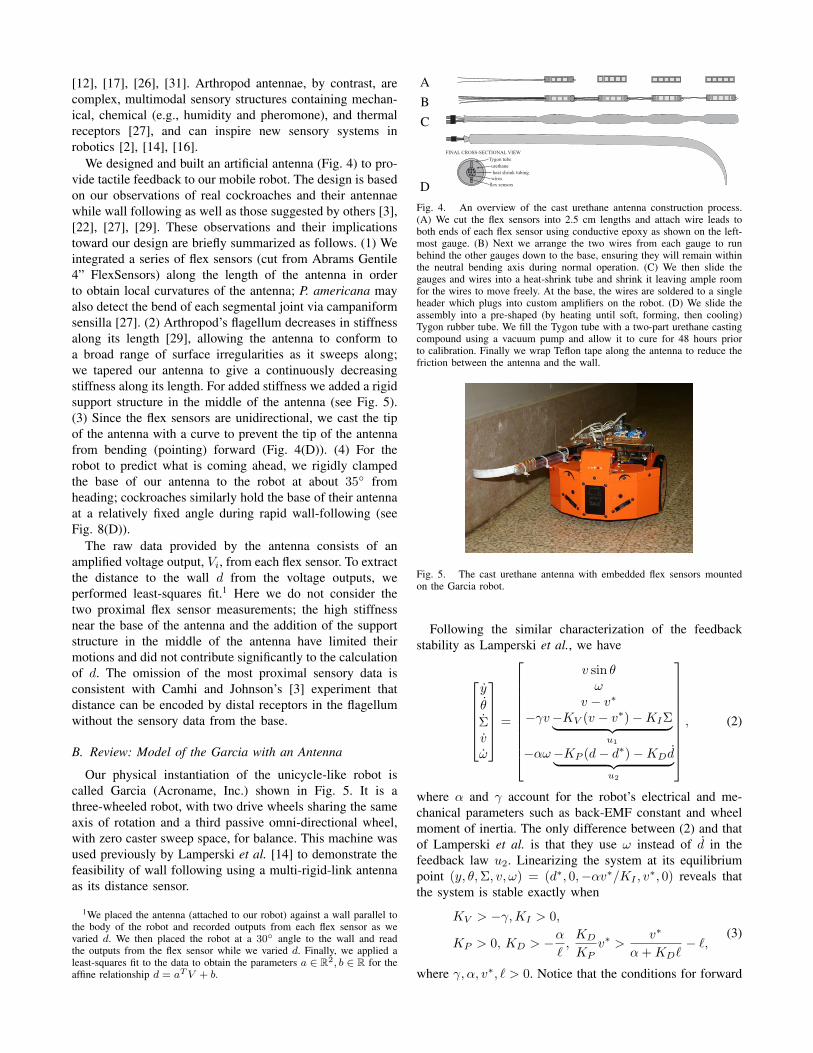
We designed and built an artificial antenna (Fig. 4) to pro-vide tactile feedback to our mobile robot. The design is basedon our observations of real cockroaches and their antennaewhile wall following as well as those suggested by others [3],[22], [27], [29]. These observations and their implicationstoward our design are briefly summarized as follows. (1) Weintegrated a series of flex sensors (cut from Abrams Gentile4” FlexSensors) along the length of the antenna in orderto obtain local curvatures of the antenna; P. americana mayalso detect the bend of each segmental joint via campaniformsensilla [27]. (2) Arthropod’s flagellum decreases in stiffnessalong its length [29], allowing the antenna to conform toa broad range of surface irregularities as it sweeps along;we tapered our antenna to give a continuously decreasingstiffness along its length. For added stiffness we added a rigidsupport structure in the middle of the antenna (see Fig. 5).(3) Since the flex sensors are unidirectional, we cast the tipof the antenna with a curve to prevent the tip of the antennafrom bending (pointing) forward (Fig. 4(D)). (4) For therobot to predict what is coming ahead, we rigidly clampedthe base of our antenna to the robot at about 35◦ fromheading; cockroaches similarly hold the base of their antennaat a relatively fixed angle during rapid wall-following (seeFig. 8(D)).
The raw data provided by the antenna consists of anamplified voltage output, Vi, from each flex sensor. To extractthe distance to the wall d from the voltage outputs, weperformed least-squares fit.1 Here we do not consider thetwo proximal flex sensor measurements; the high stiffnessnear the base of the antenna and the addition of the supportstructure in the middle of the antenna have limited theirmotions and did not contribute significantly to the calculationof d. The omission of the most proximal sensory data isconsistent with Camhi and Johnson’s [3] experiment thatdistance can be encoded by distal receptors in the flagellumwithout the sensory data from the base.
B. Review: Model of the Garcia with an Antenna
Our physical instantiation of the unicycle-like robot iscalled Garcia (Acroname, Inc.) shown in Fig. 5. It is athree-wheeled robot, with two drive wheels sharing the sameaxis of rotation and a third passive omni-directional wheel,with zero caster sweep space, for balance. This machine wasused previously by Lamperski et al. [14] to demonstrate thefeasibility of wall following using a multi-rigid-link antennaas its distance sensor.
1We placed the antenna (attached to our robot) against a wall parallel tothe body of the robot and recorded outputs from each flex sensor as wevaried d. We then placed the robot at a 30◦ angle to the wall and readthe outputs from the flex sensor while we varied d. Finally, we applied aleast-squares fit to the data to obtain the parameters a ∈ R2, b ∈ R for theaffine relationship d = aT V + b.
ABC
D
FINAL CROSS-SECTIONAL VIEWTygon tubeurethane
flex sensors
heat shrink tubingwires
Fig. 4. An overview of the cast urethane antenna construction process.(A) We cut the flex sensors into 2.5 cm lengths and attach wire leads toboth ends of each flex sensor using conductive epoxy as shown on the left-most gauge. (B) Next we arrange the two wires from each gauge to runbehind the other gauges down to the base, ensuring they will remain withinthe neutral bending axis during normal operation. (C) We then slide thegauges and wires into a heat-shrink tube and shrink it leaving ample roomfor the wires to move freely. At the base, the wires are soldered to a singleheader which plugs into custom amplifiers on the robot. (D) We slide theassembly into a pre-shaped (by heating until soft, forming, then cooling)Tygon rubber tube. We fill the Tygon tube with a two-part urethane castingcompound using a vacuum pump and allow it to cure for 48 hours priorto calibration. Finally we wrap Teflon tape along the antenna to reduce thefriction between the antenna and the wall.
Fig. 5. The cast urethane antenna with embedded flex sensors mountedon the Garcia robot.
Following the similar characterization of the feedbackstability as Lamperski et al., we have
y
θ
Σvω
=
v sin θω
v − v∗
−γv−KV (v − v∗)−KIΣ︸ ︷︷ ︸u1
−αω−KP (d− d∗)−KDd︸ ︷︷ ︸u2
, (2)
where α and γ account for the robot’s electrical and me-chanical parameters such as back-EMF constant and wheelmoment of inertia. The only difference between (2) and thatof Lamperski et al. is that they use ω instead of d in thefeedback law u2. Linearizing the system at its equilibriumpoint (y, θ,Σ, v, ω) = (d∗, 0,−αv∗/KI , v
∗, 0) reveals thatthe system is stable exactly when
KV > −γ, KI > 0,
KP > 0, KD > −α
`,
KD
KPv∗ >
v∗
α + KD`− `,
(3)
where γ, α, v∗, ` > 0. Notice that the conditions for forward

TABLE IPARAMETER VALUES FOR P. americana AND THE GARCIA.
v∗ ` α KP KD
(m/s) (m) (m−1s−2) (m−1s−1) (s−1)
P. americana 0.352 0.027 12.7 2600 433Garcia 0.5 0.139 3.53 39.16 23.49
stability—which are constraints on KV and KI—are decou-pled from the conditions on rotational stability—which areconstraints on KP and KD.
C. Dynamically-Scaled Parameters of P. americana for theGarcia
We found the necessary parameters for the Garcia usingthe principle of similitude; the APU’s torsional dynamicsequation (1) and the last row of (2) are identical, namelythey are of the form
ω = −αω −KP (d− d∗)−KDd, (4)
where α, KP , and KD are known quantities for the cock-roach [7]. Since we know α for the robot as well [14],selecting two fundamental units, v and `, leads to thefollowing dimensionless ratios:
α =α`
v∗, KP =
KP `3
v∗ 2, KD =
KD`2
v∗. (5)
Setting the desired velocity for the Garcia to 0.5 m/s andassuming α to be constant, we calculated the dimensionally-scaled look-ahead distance for the Garcia. Then we foundvalues for KP and KD in the similar way. The calculatedvalues are shown in bold in Table I (second row).
D. Experiments
The experimental setup for the Garcia was similar to thatof the cockroach behavioral experiment by Cowan et al. [7].The robot followed a wall that consisted of a straight controlwall (to allow the robot to reach its steady state) and anangled wall to act as a “step” perturbation to the internalstate, θ. We used the parameter values for the Garcia shownin Table I with KV = 1 s−1 and KI = 1 s−2. This set ofparameters satisfied the stability conditions (3).
All 30 trials at v∗ = 0.5 m/s with the 30◦ angled walldemonstrated successful turning (e.g., Fig. 8(B)). Our some-what arbitrary choice of speed gains (KV ,KI ) producedsubstantial oscillations in the forward speed (Fig. 6(A)), butnevertheless reached steady state speed within about twoseconds and did not imperil wall-following performance.
From our experiments we noticed a few undesirable behav-iors. First, the robot followed the wall with a constant errorin d (Fig. 6(B)). We believe that this was caused by the non-negligible force produced by the antenna against the wall.One remedy to this problem would be to either introduce anintegral controller or design the antenna to be less stiff (thelatter solution would be more consistent with the biology).Second, the figure shows that flex sensors 3 and 4 (E, F) didnot return to their original configuration after encountering
0 1 2 30
0.2
0.4
0.6
A. Fwd vel, v (m/s)
0 1 2 3
0.14
0.16
0.18
0.2B. Antenna measured d (m)
FilteredMeasured
0 1 2 3
11.5
22.5
E. Flex sensor 3
0 1 2 32.62.8
33.23.4
F. Flex sensor 4 (tip)0 1 2 3!40
!30!20!10
0
C. Body angle (deg)
0 1 2 300.10.20.30.4
D. Body position, y (m)
Time (sec)
Fig. 6. The Garcia’s internal states during a trial with parameters fromTable I. (d∗ = 0.17 m, v∗ = 0.5 m/s) (B,D) were obtained from theoverhead camera images. (B) shows the raw (thin) and lightly filtered (thick)d values; the Garcia used the filtered d and d in (4). (E,F) show raw voltagesfrom the respective amplifiers for flex sensors; hence, they are shown fortheir qualitative forms.
the angled wall. One possible explanation could be that thereis a range of “stable” configurations of the antenna for agiven d due to friction, memory effects, etc. A reasonablecalibration can cope with this as suggested by the fact that theGarcia was able to follow the wall successfully after makingthe turn despite the drift. Third, the Garcia failed to navigateturns of angles greater than 40◦. We believe this problem willbe addressed through the design of more flexible antennaewith more appropriately tapered mechanical stiffness.
E. Biological Implications from Robotics Experiments
Experiments performed on a robotics platform can guideresearchers in generating, refuting, and supporting biologi-cal hypotheses [10]. We see two such instances from ourexperimental result. First, the success of our trials supportsCowan et al.’s [7] work by demostrating the sufficiency ofthe PD-controller in a real-world setting with unmodeledeffects including a flexible antenna and its friction withthe wall. Our result also supports Camhi and Johnson’s [3]claim that turning, in cockroach wall following, is mediatedpredominantly by the flagellum and not necessarily the baseof the antenna; our robot controller uses only the two mostdistal flagellar segments of an antenna without the flex sensordata from the base of the antenna.
IV. THE ANTENNA-BASED LATERAL LEG SPRING(ALLS)
In the previous models, APU and the Garcia, the controlinput was literally the torque applied to the body throughcontinuous actuation. What is less clear, however, is howmight the simplest wall-following model (APU, Section II)be embedded in more elaborated anchors. Further, can we
COP a1a2
{B}
fL
MM
q2
q1
fL
fR
x
y{U}
q0
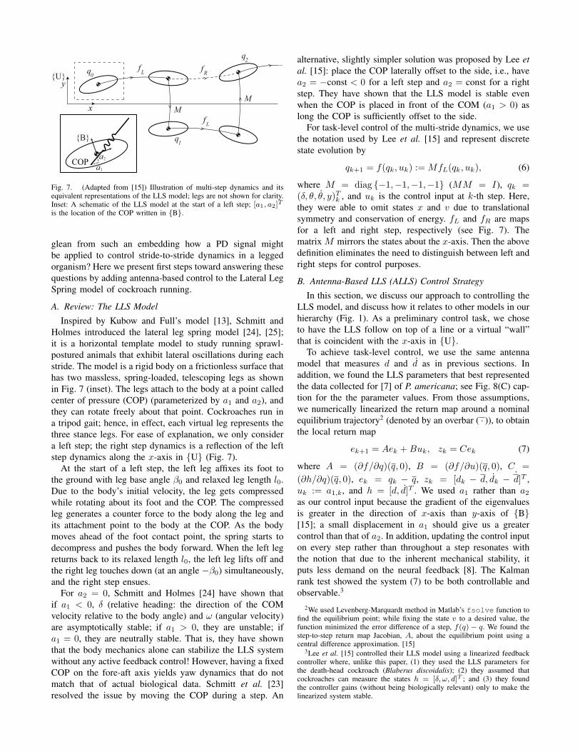
Fig. 7. (Adapted from [15]) Illustration of multi-step dynamics and itsequivalent representations of the LLS model; legs are not shown for clarity.Inset: A schematic of the LLS model at the start of a left step; [a1, a2]T
is the location of the COP written in {B}.
glean from such an embedding how a PD signal mightbe applied to control stride-to-stride dynamics in a leggedorganism? Here we present first steps toward answering thesequestions by adding antenna-based control to the Lateral LegSpring model of cockroach running.
A. Review: The LLS Model
Inspired by Kubow and Full’s model [13], Schmitt andHolmes introduced the lateral leg spring model [24], [25];it is a horizontal template model to study running sprawl-postured animals that exhibit lateral oscillations during eachstride. The model is a rigid body on a frictionless surface thathas two massless, spring-loaded, telescoping legs as shownin Fig. 7 (inset). The legs attach to the body at a point calledcenter of pressure (COP) (parameterized by a1 and a2), andthey can rotate freely about that point. Cockroaches run ina tripod gait; hence, in effect, each virtual leg represents thethree stance legs. For ease of explanation, we only considera left step; the right step dynamics is a reflection of the leftstep dynamics along the x-axis in {U} (Fig. 7).
At the start of a left step, the left leg affixes its foot tothe ground with leg base angle β0 and relaxed leg length l0.Due to the body’s initial velocity, the leg gets compressedwhile rotating about its foot and the COP. The compressedleg generates a counter force to the body along the leg andits attachment point to the body at the COP. As the bodymoves ahead of the foot contact point, the spring starts todecompress and pushes the body forward. When the left legreturns back to its relaxed length l0, the left leg lifts off andthe right leg touches down (at an angle −β0) simultaneously,and the right step ensues.
For a2 = 0, Schmitt and Holmes [24] have shown thatif a1 < 0, δ (relative heading: the direction of the COMvelocity relative to the body angle) and ω (angular velocity)are asymptotically stable; if a1 > 0, they are unstable; ifa1 = 0, they are neutrally stable. That is, they have shownthat the body mechanics alone can stabilize the LLS systemwithout any active feedback control! However, having a fixedCOP on the fore-aft axis yields yaw dynamics that do notmatch that of actual biological data. Schmitt et al. [23]resolved the issue by moving the COP during a step. An
alternative, slightly simpler solution was proposed by Lee etal. [15]: place the COP laterally offset to the side, i.e., havea2 = −const < 0 for a left step and a2 = const for a rightstep. They have shown that the LLS model is stable evenwhen the COP is placed in front of the COM (a1 > 0) aslong the COP is sufficiently offset to the side.
For task-level control of the multi-stride dynamics, we usethe notation used by Lee et al. [15] and represent discretestate evolution by
qk+1 = f(qk, uk) := MfL(qk, uk), (6)
where M = diag {−1,−1,−1,−1} (MM = I), qk =(δ, θ, θ, y)T
k , and uk is the control input at k-th step. Here,they were able to omit states x and v due to translationalsymmetry and conservation of energy. fL and fR are mapsfor a left and right step, respectively (see Fig. 7). Thematrix M mirrors the states about the x-axis. Then the abovedefinition eliminates the need to distinguish between left andright steps for control purposes.
B. Antenna-Based LLS (ALLS) Control Strategy
In this section, we discuss our approach to controlling theLLS model, and discuss how it relates to other models in ourhierarchy (Fig. 1). As a preliminary control task, we choseto have the LLS follow on top of a line or a virtual “wall”that is coincident with the x-axis in {U}.
To achieve task-level control, we use the same antennamodel that measures d and d as in previous sections. Inaddition, we found the LLS parameters that best representedthe data collected for [7] of P. americana; see Fig. 8(C) cap-tion for the the parameter values. From those assumptions,we numerically linearized the return map around a nominalequilibrium trajectory2 (denoted by an overbar ( · )), to obtainthe local return map
ek+1 = Aek + Buk, zk = Cek (7)
where A = (∂f/∂q)(q, 0), B = (∂f/∂u)(q, 0), C =(∂h/∂q)(q, 0), ek = qk − q, zk = [dk − d, dk − d]T ,uk := a1,k, and h = [d, d]T . We used a1 rather than a2
as our control input because the gradient of the eigenvaluesis greater in the direction of x-axis than y-axis of {B}[15]; a small displacement in a1 should give us a greatercontrol than that of a2. In addition, updating the control inputon every step rather than throughout a step resonates withthe notion that due to the inherent mechanical stability, itputs less demand on the neural feedback [8]. The Kalmanrank test showed the system (7) to be both controllable andobservable.3
2We used Levenberg-Marquardt method in Matlab’s fsolve function tofind the equilibrium point; while fixing the state v to a desired value, thefunction minimized the error difference of a step, f(q)− q. We found thestep-to-step return map Jacobian, A, about the equilibrium point using acentral difference approximation. [15]
3Lee et al. [15] controlled their LLS model using a linearized feedbackcontroller where, unlike this paper, (1) they used the LLS parameters forthe death-head cockroach (Blaberus discoidalis); (2) they assumed thatcockroaches can measure the states h = [δ, ω, d]T ; and (3) they foundthe controller gains (without being biologically relevant) only to make thelinearized system stable.

Here we make several approximations to the ALLS modelto simplify control and connect the ALLS to a simplermodel in our research program (Fig. 1). The third rowof the linearized discrete dynamics (7) for parameters forP. americana can be written as
ωk+1−ωk = −(1.96)ωk− (1.07)(δk− δ)+(616.5)uk. (8)
The eigenvalue associated with the relative heading, δ, isquite fast (λδ = 0.24), and our simulations confirm that δk−δwas at least an order of magnitude smaller than the otherterms during transients. So we approximate (8) by neglectingδk − δ and approximate ω ≈ (ωk+1 − ωk)fs, where fs =12 Hz (unpublished stride frequency data from [7]) is thestride frequency. Thus, we rescale the input and approximate(8) with a continuous-time system,
ω ≈ −αω + u′, (9)
where α ≈ 23.5 and u′ ≈ (7398)uk. This equation mirrorsthe unicycle model (1), and despite the fairly crude approxi-mations, the coefficient α ≈ 23.5 in the LLS approximation(9) is within the confidence intervals of the fitted parametersfor α in cockroaches (Table I). Also note that the u in (1) isa moment (scaled by inertia), whereas in the ALLS model,the control input is the COP position. Hence the coefficientmultiplying the control uk in (9) has been absorbed into u′
for comparison purposes.The similarity between the two equations, although a
rough approximation, has revealed the possibility that thesame control structure, u′ = −KP d − KDd, with the sameparameters that were fitted to the cockroach and applied tothe Garcia model, may be applicable to the ALLS. Usingthese gains have yielded closed loop system of ek+1 =(A + BKC)ek with all of its eigenvalues (−0.60 ± j0.10and −0.23± j0.50) inside the unit circle.
Simulation for this controller using the parameters forP. americana is shown in Fig. 8(C). In this control law, COPlies nominally along the body y-axis, namely a1 = 0 anda2 = −3 mm (for the left step); the feedback controllervaries the COP in the a1 direction and the value for a1 issaturated to ±7 mm.
C. Toward a Motor Control Strategy for Sensor-Based Task-Level Maneuvering in Legged Runners
The most parsimonious controller sufficient to stabilizehigh-speed wall following in the APU model is a continuousPD-controller mapping antenna measurements to a contin-uous moment about the COM. Above, we show that thiscontrol law applies with essentially no modification to thecontrol of a legged running model, ALLS, by mapping sensorvalues to the COP position during each step. The next stepfrom this work is to find evidence in running animals thatlinks the actual COP motion to the sensory stimulus. The ex-perimental paradigm would consist of cockroaches followingalong a wall with perturbations [3], [7], while individual legforces and kinematics are measured to recover COP motions[30]. Together, these data can be used to approximate themapping from antennal measurements to COP motions. From
the above modeling, we hypothesize that the motion of theCOP from step to step is governed by a PD controller,whose parameters are given in Table I. Looking further,increasingly anchored models which represent cockroachkinematics with increasing biofidelity can be used to teaseapart the contributions of individual legs during turning [11],again within our template-anchor research program. With thisbiological understanding, we will be poised to create bio-inspired control strategies for hexapedal robots that shift theCOP based on sensory stimuli.
V. CONCLUSION
Our research program (Fig. 1) integrates models andexperiments at several levels of complexity, from the simple3 degree-of-freedom (DOF) APU, up to the animal itselfwith orders of magnitude more mechanical DOFs. The resultis a multifaceted view (Fig. 8) of one of the most extraor-dinary reflex-driven locomotor behaviors ever studied [3]:high-speed antenna-based wall following in the Americancockroach.
While it may come as no surprise that a wheeled robotcan successfully follow a wall at high speed under PD-control, it is surprising that such a simple control mechanismmay underly the control of one of Nature’s fastest terrestrialinsects [18]. This paper presents evidence from several levelsof mathematical models and robotics experiments that justsuch a mechanism may be in place. Along the way, weconstructed a cockroach-inspired tactile sensor that can beused for new robotics applications, and to test new biologicalhypotheses. Future iterations of this reciprocal inspirationof biology, modeling, and robotics promise to continueelucidating the principles that underly biological control, andlead to the design of dynamic, maneuverable legged robots.
VI. ACKNOWLEDGMENTS
Thanks to Brett Kutscher for help with software andhardware integration on the Garcia robot. Thanks to SimonSponberg, Robert Full and Andrew Lamperski for theircomments on the manuscript. Thanks to John Schmitt forproviding significant insight into the subtleties of the LateralLeg Spring model.
REFERENCES
[1] R. Altendorfer, D. E. Koditschek, and P. Holmes. Stability analysisof a clock-driven rigid-body slip model for rhex. The InternationalJournal of Robotics Research, 2004.
[2] T. Barnes, T. Truong, G. Adams, and N. McGruer. Large deflectionanalysis of a biomimetic lobster robot antenna due to contact and flow.Transactions of the ASME, 68:948–951, 2001.
[3] J. M. Camhi and E. N. Johnson. High-frequency steering maneuversmediated by tactile cues: antenna wall-following in the cockroach. JExp Bio, 202:631–643, 1999.
[4] J. G. Cham, S. A. Bailey, J. E. Clark, R. J. Full, and M. R. Cutkosky.Fast and robust: Hexapedal robots via shape deposition manufacturing.The International Journal of Robotics Research, 21(10), 2002.
[5] T. P. Chapman and B. Webb. A model of antennal wall-following andescape in the cockroach. J Comp Physiol A Neuroethol Sens NeuralBehav Physiol, 192(9):949–969, Sep 2006.
[6] N. J. Cowan and E. S. Fortune. The critical role of locomotiondynamics in decoding sensory systems. J Neurosci, 27(5):1123–1128,2007.

Body
Pos
ition
, y (c
m)
2
0
- 2
25 300 5 10 15 20Body Position, x (cm)
35
0
- 20
- 40 Body
Ang
le, θ
(deg
)
−40 −20 0 20 40 60 80Body Position, x (cm)
Body
Ang
le, θ
(deg
)
Body
Pos
ition
, y (c
m)
- 10
- 20
- 30
0
Body
Pos
ition
, y (c
m) 2
0
- 2
Body
Ang
le, θ
(deg
)
0 5 10 15 20Body Position, x (cm)
20
0
- 20
- 40
20
0
−20
A
D
C
B
Body
Ang
le, θ
(deg
)
0
- 20
- 40Body
Pos
ition
, y (c
m) 2
0
- 20 5 10 15
Body Position, x (cm)
Fig. 8. Subplots (A-D) show the task-space trajectories of severalmodels and physical systems from our research program (Fig. 1), allwith approximately dimensionally equivalent parameters, and the same PDcontrol law in each case: (A) APU model; (B) the Garcia with antenna,where the robot is shown every other “stride”; (C) the ALLS model shownat the start of every step with *’s indicating COM, ×’s indicating COP;the straight lines emanating from ×’s depicts LLS’s leg; (D) a typicaltrial of P. americana (the cockroach is shown every other stride). For(C): m = 0.77× 10⁻³ kg, J = 1.0× 10⁻⁷ kgm2, l0 = 0.021 m,k = 0.944 N/m, β0 = 1.138 rad, a1 = 0 m, a2 = −0.003 m,v(0) = 0.425 m/s.
[7] N. J. Cowan, J. Lee, and R. J. Full. Task-level control of rapid wallfollowing in the American cockroach. J Exp Bio, 209(9):1617–1629,2006.
[8] R. J. Full and D. E. Koditschek. Templates and anchors: neu-romechanical hypotheses of legged locomotion on land. J Exp Bio,202(23):3325–3332, 1999.
[9] R. J. Full and M. S. Tu. Mechanics of a rapid running insect: two-,four-, and six-legged locomotion. J Exp Bio, 156:215–231, 1991.
[10] P. Holmes, R. J. Full, D. Koditschek, and J. Guckenheimer. Thedynamics of legged locomotion: Models, analyses, and challenges.SIAM Review, 48(2):207–304, 2006.
[11] D. L. Jindrich and R. J. Full. Many-legged maneuverability: Dynamicsof turning in hexapods. J Exp Bio, 202(12):1603–1623, 1999.
[12] M. Kaneko, N. Kanayama, and T. Tsuji. Active antenna for contactsensing. IEEE Transactions on Robotics and Automation, 14(2):278–291, 1998.
[13] T. M. Kubow and R. J. Full. The role of the mechanical system incontrol: a hypothesis of self-stabilization in hexapedal runners. Philo-sophical Transactions of the Royal Society of London SerieseoleolB-Biological Sciences, 354(1385):849–861, 1999.
[14] A. Lamperski, O. Loh, B. Kutscher, and N. J. Cowan. Dynamicalwall-following for a wheeled robot using a passive tactile sensor. InInternational Conference on Robotics and Automation, pages 3838–3843, 2005.
[15] J. Lee, A. Lamperski, J. Schmitt, and N. J. Cowan. Task-Level Controlof the Lateral Leg Spring Model of Cockroach Locomotion, volume340 of Lecture Notes in Control and Information Sciences. Heidelberg:Springer-Verlag, 2006.
[16] W. A. Lewinger, C. M. Harley, R. E. Ritzmann, M. S. Branicky, andR. D. Quinn. Insect-like antennal sensing for climbing and tunnelingbehavior in a biologically-inspired mobile robot. In IEEE InternationalConference on Robotics and Automation, 2005.
[17] M. Lungarella, V. V. Hafner, R. Pfeifer, and H. Yokoi. An artificialwhisker sensor for robotics. In Proceedings of the 15th IEEE/RSJInternational Conference on Intelligent Robots and Systems (IROS),pages 2931–2936, Lausanne, Switzerland, 2002.
[18] T. M. Merritt. Book of Insect Records, chapter Fastest Runner.University of Florida, 1999. http://ufbir.ifas.ufl.edu/.
[19] R. D. Quinn, G. M. Nelson, R. J. Bachmann, D. A. Kingsley, J. T.Offi, T. J. Allen, and R. E. Ritzmann. Parallel complementarystrategies for implementing biological principles into mobile robots.The International Journal of Robotics Research, 22:169–186, 2003.
[20] U. Saranli. SimSect hybrid dynamical simulation environment. Tech-nical Report CSE-TR-436-00, UM, Ann Arbor, MI, 2000.
[21] U. Saranli, M. Buehler, and D. E. Koditschek. RHex: A simpleand highly mobile hexapod robot. International Journal of RoboticsResearch, 20(7):616–631, 2001.
[22] R. Schafer and T. V. Sanchez. Antennal sensory system of thecockroach, Periplaneta americana: postembryonic development andmorphology of the sense organs. J. Comp. Neurol., 149:335–354,1973.
[23] J. Schmitt, M. Garcia, R. C. Razo, P. Holmes, and R. J. Full. Dynamicsand stability of legged locomotion in the horizontal plane: a test caseusing insects. Biol Cybern, 86:343–353, 2002.
[24] J. Schmitt and P. Holmes. Mechanical models for insect locomotion:dynamics and stability in the horizontal plane I. Theory. Biol Cybern,83:501–515, 2000.
[25] J. Schmitt and P. Holmes. Mechanical models for insect locomotion:dynamics and stability in the horizontal plane-II. Application. BiolCybern, 83:517–527, 2000.
[26] A. E. Schultz, J. H. Solomon, M. A. Peshkin, and M. J. Hartmann.Multifunctional whisker arrays for distance detection, terrain mapping,and object feature extraction. In IEEE International Conference onRobotics and Automation, 2005.
[27] G. Seelinger and T. R. Tobin. The American Cockroach, chapter SenseOrgans, pages 217–245. Chapman and Hall Ltd, 11 New Feetter Lane,London EC4P 4EE, 1982.
[28] J. Seipel, P. Holmes, and R. Full. Dynamics and stability of insectlocomotion: a hexapedal model for horizontal plane motions. BiolCybern, 91(2):76–90, 2004.
[29] E. Staudacher, M. Gebhardt, and V. Durr. Antennal movements andmechanoreception: Neurobiology of active tactile sensors. Advancesin Insect Physiology, 32:49–205, 2005.
[30] L. H. Ting, R. Blickhan, and R. J. Full. Dynamic and static stabilityin hexapedal runners. J Exp Biol, 197:251–269, 1994.
[31] N. Ueno, M. Svinin, and M. Kaneko. Dynamic contact sensing byflexible beam. IEEE/ASME Transactions on Mechatronics, 3(4):254–263, 1998.