A Heartbeat and Temperature Measuring System for …€¦ · · 2017-10-27The measurement of...
20
International Journal of Bio-Science and Bio-Technology Vol.8, No.1 (2016), pp.171-190 http://dx.doi.org/10.14257/ijbsbt.2016.8.1.16 ISSN: 2233-7849 IJBSBT Copyright ⓒ 2016 SERSC A Heartbeat and Temperature Measuring System for Remote Health Monitoring using Wireless Body Area Network Mohammad Wajih Alam 1* , Tanin Sultana 2 and Mohammad Sami Alam 3 1 Department of Biomedical Engineering, School of Electrical Engineering, University of Ulsan, Ulsan, South Korea 2 Department of Electrical and Electronic Engineering, Chittagong University of Engineering and Technology, Chittagong, Bangladesh 3 Department of Electronics and Communication Engineering, Lovely Professional University, Punjab, India 1 [email protected], 2 [email protected], 3 [email protected] Abstract This paper presents the design and development of a microcontroller based heartbeat and body temperature monitor using fingertip and temperature sensor. The device uses the optical technology to detect the flow of blood through the finger and offers the advantage of portability over conventional recording systems. However, wireless body area network based remote patient monitoring systems have been presented with numerous problems including efficient data extraction and dynamic tuning of data to preserve the quality of data transmission. Evaluation of the device on real signals shows accuracy in heartbeat measurement, even under intense physical activity. This paper presents these challenges as well as solution to these problems by proposing an architecture which allows a network to be formed between the patient and doctor in order to enable remote monitoring of patient by analyzing the data of patient. The device consists of sensors which are used to measure heartbeat as well as body temperature of a patient and it is controlled by a central unit. The readings from these sensors are further processed and sent via GSM module to a remote location where it is displayed on cell phone. The optical heartbeat sensor counts the heartbeat per minute and temperature sensor measures the temperature from the body and both the measured data are sent to a receiving end utilizing wireless technology where the data is displayed in a cell phone for further processing and patient care. Moreover, the superiority of this device is shown in comparison to traditional system. Keywords: Microcontroller, Heartbeat, Body temperature, RF module, GSM module, Remote Monitoring and Fingertip Sensor 1. Introduction Heartbeat is the number of heart beats per unit of time which is generally expressed in beats per minute (bpm). Heart beat can change as the body needs to absorb oxygen and release carbon dioxide. It alters during exercise or at rest. The measurement of heart beat is mostly used by medical professionals as a primary test to help in the diagnosis and tracking of the medical conditions [1]. It is also used by the individuals who are involved in intense physical training, such as athletes who are greatly involved in monitoring of their heart rate to achieve maximum efficiency. Due to sudden change in lifestyle and unhealthy eating habits, the incidents of heart and vascular diseases are found to increase in a dramatic manner. Moreover, heart problems are being increasingly diagnosed on younger patients [2]. Coronary heart disease is now considered as one of the leading cause of death around the globe. Thus, any kind of progress in this field which will improve the
-
Upload
truongtuong -
Category
Documents
-
view
214 -
download
1
Transcript of A Heartbeat and Temperature Measuring System for …€¦ · · 2017-10-27The measurement of...

International Journal of Bio-Science and Bio-Technology
Vol.8, No.1 (2016), pp.171-190
http://dx.doi.org/10.14257/ijbsbt.2016.8.1.16
ISSN: 2233-7849 IJBSBT
Copyright ⓒ 2016 SERSC
A Heartbeat and Temperature Measuring System for Remote
Health Monitoring using Wireless Body Area Network
Mohammad Wajih Alam1*
, Tanin Sultana2
and Mohammad Sami Alam3
1Department of Biomedical Engineering, School of Electrical Engineering,
University of Ulsan, Ulsan, South Korea 2Department of Electrical and Electronic Engineering, Chittagong University of
Engineering and Technology, Chittagong, Bangladesh 3Department of Electronics and Communication Engineering, Lovely Professional
University, Punjab, India [email protected],
Abstract
This paper presents the design and development of a microcontroller based heartbeat
and body temperature monitor using fingertip and temperature sensor. The device uses
the optical technology to detect the flow of blood through the finger and offers the
advantage of portability over conventional recording systems. However, wireless body
area network based remote patient monitoring systems have been presented with
numerous problems including efficient data extraction and dynamic tuning of data to
preserve the quality of data transmission. Evaluation of the device on real signals shows
accuracy in heartbeat measurement, even under intense physical activity. This paper
presents these challenges as well as solution to these problems by proposing an
architecture which allows a network to be formed between the patient and doctor in order
to enable remote monitoring of patient by analyzing the data of patient. The device
consists of sensors which are used to measure heartbeat as well as body temperature of a
patient and it is controlled by a central unit. The readings from these sensors are further
processed and sent via GSM module to a remote location where it is displayed on cell
phone. The optical heartbeat sensor counts the heartbeat per minute and temperature
sensor measures the temperature from the body and both the measured data are sent to a
receiving end utilizing wireless technology where the data is displayed in a cell phone for
further processing and patient care. Moreover, the superiority of this device is shown in
comparison to traditional system.
Keywords: Microcontroller, Heartbeat, Body temperature, RF module, GSM module,
Remote Monitoring and Fingertip Sensor
1. Introduction
Heartbeat is the number of heart beats per unit of time which is generally expressed in
beats per minute (bpm). Heart beat can change as the body needs to absorb oxygen and
release carbon dioxide. It alters during exercise or at rest. The measurement of heart beat
is mostly used by medical professionals as a primary test to help in the diagnosis and
tracking of the medical conditions [1]. It is also used by the individuals who are involved
in intense physical training, such as athletes who are greatly involved in monitoring of
their heart rate to achieve maximum efficiency. Due to sudden change in lifestyle and
unhealthy eating habits, the incidents of heart and vascular diseases are found to increase
in a dramatic manner. Moreover, heart problems are being increasingly diagnosed on
younger patients [2]. Coronary heart disease is now considered as one of the leading cause
of death around the globe. Thus, any kind of progress in this field which will improve the

International Journal of Bio-Science and Bio-Technology
Vol.8, No.1 (2016)
172 Copyright ⓒ 2016 SERSC
diagnosis and treatment of patient is always welcomed by medical community. Heartrate
is usually measured in controlled environment in clinics, but it is of great need that a
system must be designed so that the patient will be able to monitor their health in their
home as well. This will enhance the system performance while offering the advantage of
portability over other conventional systems.
A heart beat monitor (HBM) is a simple and economical device which calculates a
sample of the heartrate signal and measures the beats per minute which allows utilization
of the information for easy monitoring of heart condition. The HBM devices employ
electrical and optical methods as means for detecting and achieving the heart signals. So,
the wireless technology is utilized in order to meet the requirement of remote control and
patient monitoring. The remote patient monitoring [3] is a technology which provides us
with the opportunity to monitor the patient outside the hospitals by reducing the need of
visiting the patient which saves both the time and money of patient and doctor while
increasing the efficiency along with the reliability of health services.
Heartbeat and body temperature are very important parameters that are routinely
measured whenever a patient arrives in a hospital which makes heartbeat one of the very
significant property of cardiovascular system. The heart rate of a healthy adult at rest is
around 72 bpm [4]. Athletes normally have lower heart rate than less active people which
leads us to the fact that the persons who are more excessively involved in exercise or
physical training are more likely to have less heart rate than those who are not involved in
intense exercise. Small babies tend to have much higher heartbeat (120 bpm) in
comparison to older children (90 bpm). Heart rate increases during exercise while it
returns back to normal rate slowly after the exercise is finished. The rate at which the
heart rate returns back to normal value is an indication of the fitness of a person. If the
heart rate is lower than the normal heart rate, then it is normally an indication of
bradycardia while if the heart rate is higher than the normal heart rate, then the condition
is known as tachycardia [5].
Similarly, the body temperature also changes from one person to another and varies
throughout the day. The body temperature is found to be lowest in the early morning
while it is highest during the early evening. It is necessary to monitor the changes
regularly. An average human adult has normal body temperature of around 37oC or 98.6
oF
[6]. However, it is difficult to define an accurate value of body temperature as it varies
according to daytime, age and physical state of a person. So, the normal body temperature
of a healthy person can be 36.1oC (97
oF) in the early morning and can rise up to 37.2
oC
(99oF). Hence, normal range of body temperature of a healthy adult varies between 97
oF
and 100oF or 36.1
oC and 37.8
oC [7]. The temperature sensor used here is LM35. This
temperature sensor generates an analog output voltage that is proportional to the
temperature. So, this temperature sensor requires an analog to digital converter to convert
the analog output voltage to a digital form [8]. For this reason, a microcontroller of model
PIC16F73 is used to convert the analog value to a digital form in order to send the
measured data to a remote end.
A wireless heartbeat and temperature monitoring system has been proposed before
using radiofrequency (RF) module [9]. But it has some limitations as described in section
6 and 7. With the advancement of technology, both quality of security [10] and health in
human life is increasing day by day. This paper presents the design of a very low cost
remote patient monitoring system which will measure heart rate and body temperature of
an individual and the measured data will be sent to a remote end where the data will be
displayed on a mobile device using GSM module. This device will help both the patient
and doctor during emergency period by saving both time and cost of patient and
physician.

International Journal of Bio-Science and Bio-Technology
Vol.8, No.1 (2016)
Copyright ⓒ 2016 SERSC 173
2. System Hardware
The proposed heartbeat and temperature monitoring device is intended to have the
following features:
The system utilizes an optical mechanism to measure the modulations generated by
electrical or physical variations in the heart movements.
Wired communication is eradicated.
Real time monitoring of the patient is possible.
The doctor does not need to visit the patient to monitor him/her.
Time is saved for both patients and doctor.
Helpful in emergency period.
Routine checking of the patient can be done easily.
Useful for remote areas.
Once installed, the maintenance cost is very low.
Easy to use (Even illiterate people can operate it).
Increases access to health care while decreasing the healthcare delivery costs.
The device utilizes a GSM module to send the data in the form of SMS to a mobile
device for better portability of the system.
The device has a functionality of showing both the time and date of the measured
data.
Figure 1. Block Diagram of the Complete System
To manufacture a device with above features, figure 1 shows the block diagram of the
complete system in which the device consists of a PIC16F73 microcontroller for
measuring and transmitting the data to a remote end on a mobile device. The measured
data of heartbeat and body temperature is sent to a remote end with the help of a GSM
module. For measuring heartbeat, the device utilizes a photo diode and a bright LED
along with an amplifier and a filter circuit. For measuring the body temperature, the
device uses LM35 IC. The device measures heartbeat and temperature of the body and
transmits the data wirelessly with the help of the GSM module. The data, which consists
of heartbeat and body temperature, is received at a mobile device and can be transferred
to a pc using Nokia PC suite. Thus the data can be stored and viewed for future reference.
Figure 1 shows the complete block diagram showing all the necessary components of the
system. This section describes the system hardware in detail.
2.1. Heartbeat Measuring Unit
Heartbeat is measured with the help of fingertip sensor which consists of an infra-red
(IR) light emitting diode transmitter and an IR photo detecting receiver. The IR light

International Journal of Bio-Science and Bio-Technology
Vol.8, No.1 (2016)
174 Copyright ⓒ 2016 SERSC
passes through the tissues and variations in the volume of blood within the finger
determine the amount of light that is incident on the IR detector.
Figure 2. Arrangement of Sensors
Figure 2 shows the arrangement of sensors for measuring the heartbeat of a patient.
The device utilizes optical technology to measure heartbeat of patient. As shown in the
figure, both the IR transmitter and receiver could be placed on the same plane and the
finger would function as a reflector of the incident light. The IR receiver monitors the
reflected signal in this case. The IR filter of the photo transistor reduces interference from
the mains 50Hz noise. The IR LED is forward biased through a resistor to create a current
flow. The values of resistors are chosen so that they can produce the maximum amount of
light output. The photo-resistor is placed in series with the resistor to reduce the current
drawn by the detection system and to prevent short-circuiting of the power supply when
no light is detected by the photo resister. This device makes the use of optical sensor to
detect the heartbeat of the patient. The optical sensor along with the combination of the
infrared light emitting diode, also known as IR LED and IR photodiode senses the
heartbeat of the patient and finally produces a weak output signal. The output signal
received from these diodes is amplified and filtered and finally fed to the microcontroller.
The microcontroller processes the data received from the sensors. The fingertip sensor
consists of a photodiode and a bright LED. The LED and the photodiode are attached in
an adjacent position so that the finger acts as a reflector for infra-red light. The light from
bright LED collides with the tissues of the finger that is put above the bright LED and the
photo diode. The blood is continuously changing inside the tissues of the finger which
results in the variation of blood due to which there is variation of reflected light that the
photo diode is going to detect. The bright LED and the photodiode are attached tightly so
that they could have tight grasp while detecting the heartbeat. The resistor values are
adjusted so that the optimum light passes through the finger which will enable the device
to detect the heartbeat.
2.2. Amplification and Filtering
The photodiode detects the infra-red light reflected by the finger. It detects the
variation in the blood volume with respect to the heartbeat and finally generates a pulse at
the output of the photodiode. The signal produced from photodiode is very weak and
small which is required to be increased in magnitude. This signal is very weak that it
cannot be detected by the microcontroller directly. Thus, the signal is amplified using an
operational amplifier. The operational amplifier used for this purpose is LM358. This
operational amplifier is provided with two of the independent high gain, frequency
International Journal of Bio-Science and Bio-Technology
Vol.8, No.1 (2016)
Copyright ⓒ 2016 SERSC 175
compensated operational amplifier which is designed to function from a single supply
over a wide range of voltages which means that this amplifier is capable of amplifying the
signal in two stages making the device able to detect the signal and in turn measure the
heartbeat. This device uses two stages for amplification process as shown in Figure 3.
This device uses non-inverting amplifier for amplifying purpose in both the stages. The
operational amplifier can be considered as a low power quad operational amplifier. The
signal is amplified to an appropriate voltage level so that the pulses can be counted by the
microcontroller.
The signal generated from the photo diode also contains noise which is required to be
filtered otherwise the obtained signal will contain noise of some types making the
measurement complex. Moreover, the interference produced due to the movement of
artefacts and the mains supply of 50Hz can also affect the signal. The standard ECG
signal of heartbeat has frequency component which varies in the range of 0.05-200Hz.
When this signal is filtered, the frequency component varies in the range of 0-50Hz. Thus,
the filtration does not affect the quality of the signal. The information contained in the
signal is not lost. The circuit arrangement for amplification and filter stage is shown in
Figure 3. The filter arrangement that is used in this research is low pass filter that
eliminates higher frequency components. Here the resistors and the capacitors are
arranged in such a way that the combination acts as a low pass filter and blocks higher
frequency noise components that are present in the signal. The capacitor is used at the
input terminal of the amplifier to block the dc component in the signal. Finally, a red LED
is placed at the output of the amplifier and filter stage to show that the device is working
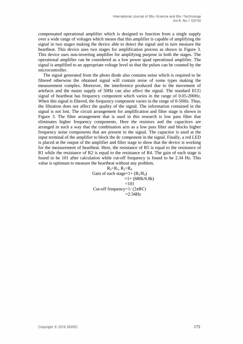
for the measurement of heartbeat. Here, the resistance of R5 is equal to the resistance of
R1 while the resistance of R2 is equal to the resistance of R4. The gain of each stage is
found to be 101 after calculation while cut-off frequency is found to be 2.34 Hz. This
value is optimum to measure the heartbeat without any problem.
R5=R1, R2=R4
Gain of each stage=1+ (R5/R4)
=1+ (680k/6.8k)
=101
Cut-off frequency=1/ (2πRC)
=2.34Hz

International Journal of Bio-Science and Bio-Technology
Vol.8, No.1 (2016)
176 Copyright ⓒ 2016 SERSC
Figure 3. Circuit Arrangement of Amplifier and Filter Stages
2.3. Temperature Measuring Unit
The temperature monitoring unit consists of the components that are required to
measure the temperature of the body. This unit comprises of a temperature sensor which
measures the temperature of the body and is connected directly to a microcontroller. The
temperature sensor that is used in this circuit is LM35 for the measurement of the body
temperature. This temperature sensor is an analog sensor which produces an analog
voltage by sensing the temperature. This sensor is held by the finger for a while (about 15
sec) in order to measure the body temperature. The body temperature on the body surface
is about 1 degree centrigade less than the temperature of other parts. The analog voltage
produced by the LM35 temperature sensor is directly proportional to the body
temperature. The analog voltage needs to be converted to a digital value. For the
conversion, the microcontroller PIC16F73 is used which has a built-in analog to digital
converter due to which an extra component for converting analog voltage to digital
voltage is removed and the circuit configuration becomes less bulky. The digital
equivalence of analog voltage produced by LM35 sensor can now be used by the
microcontroller for further processing. The microcontroller receives the data in analog
form and converts it into digital form then sends it to the GSM module so that the data
can be sent to the remote end. At the receiving end, a mobile device which utilizes the
GSM system receives the message. The message received at the mobile device is
displayed at the screen along with the data of heartbeat. The data shown in the screen also
shows the date and time of the measurement.
The LM35 is a precision integrated circuit temperature sensor that is used here to
measure temperature. The electrical output voltage of LM35 is linearly proportional to
the celsius or centigrade temperature. The LM35 has an advantage over linear temperature
sensors calibrated in degree Kelvin, as it is not required to subtract a large constant
voltage from its output to obtain convenient Centigrade scaling. Besides, the LM35
does not require any external calibration or trimming to provide typical accuracies of
+/- 1/4 degree C at room temperature and +/- 8/4 degree C. The trimming and calibration
are done at wafer level. So, it is an inexpensive device. It can be used with single power

International Journal of Bio-Science and Bio-Technology
Vol.8, No.1 (2016)
Copyright ⓒ 2016 SERSC 177
supplies, or with plus and minus supplies. As it draws only 60 µA from its supply, it has
very low self-heating, less than 0.10 in still air. Thermistor can also be used for
temperature measuring. Another reason for using LM35 is that it accurately measures the
temperature in comparison to thermistor and it is not subjected to oxidation as the sensor
circuitry is sealed. Besides, the output voltage of LM35 does not need to be amplified.
The low output impedance, linear output and precise inherent calibration of the LM35
make its interfacing to control circuitry very easy. Moreover, the LM35 is rated to operate
over a -55 oC to +150
oC temperature range. The output voltage varies by 10 mV in
response to every oC rise/fall in ambient temperature, i.e. its scale factor is 0.01 V/
oC. For
measuring temperature of a patient, the left pin and right pin of LM35 is connected to the
power (5V) supply and ground respectively. The middle pin generates analog voltage that
is directly proportional to the temperature. Here, analog voltage is independent of power
supply. Thus, the middle pin is connected to the microcontroller PIC16F73 at port A for
further processing. The microcontroller has ADC in it and it keeps the digital data in the
memory.
2.4. GSM Module
The GSM module used in this project is SIM 908-C. This module is designed for
covering global market. It is combined with a high performance GSM engine. It works at
a frequency of GSM 850MHz. It offers best class acquisition and tracing sensitivity
features, Time to first fix (TTFF) and accuracy. The size of this module is 50mm x 33mm
x 8.8mm. It can meet almost all the requirements for space in user applications, such as
M2M devices. This module has a 60-PIN DIP connector and provides all hardware
interfaces between the module and the customer board. It consists of a serial port and a
debug port that can help users to easily develop the user’s applications. Moreover, this
module comes with power saving technique so that the consumption of current is as low
as 1 mA during sleep mode. The essential features of GSM module for this application
are:
The power consumption is about 1 mA in sleep mode.
The frequency band is GSM 850.
It consists of power transmitting feature of class 4 (2W) at GSM 850.
Normal temperature range for operation is -30oC to +80
oC.
The SMS storage is on SIM card.
The sim interface supports a SIM card of 1.8V and 3V.
The physical characteristics include the size of 500mm x 33mm x 8.8mm.
The weight of this module is 11.1g.

International Journal of Bio-Science and Bio-Technology
Vol.8, No.1 (2016)
178 Copyright ⓒ 2016 SERSC
Net_Light
1
3
5
7
2
4
6
8
9 10
11 12
13 14
15 16
17
19
21
18
20
22
23 24
25 26
27
29
28
30
31
33
35
32
34
36
37 38
39 40
41 42
43 44
45
47
49
46
48
50
51 52
53 54
55
57
56
58
59 60
52610-3071
PWR_KEY
NET_LIGHT
RXD
TXD
RTS
CTS
DCD
RI
DTR
VB
AT
4k7
AK
STATUS
SIM VDD
SIM_RST
SIM_DATA
SIM_CLK
Figure 4. Pin Diagram of GSM Module
Figure 4 shows the detailed pin diagram of GSM module of model no. SIM908-C. It
shows that the pin 2, 4, 6 and 8 are connected to VBAT while pin 16 of the module is
connected to Net Light which shows the network status. Pin 20 is grounded with the help
of pin 40. The LED between pin 20 and 40 gives the status of the GSM module.
Similarly, pin 1was connected to ground along with pin 3, pin 5, pin 7 and pin 39. Pin 13
is connected to the power key while pin 17 is connected to Sim VDD. Similarly, pin 19 is
connected to Sim RST while pin 21 is connected to Sim Data. Moreover, pin 23 is
connected to Sim CLK and pin 25 is connected to DCD. Likewise pin 27, 29, 31, 33, 35
and 37 are connected to DTR, RXD, TXD, RTS, CTS and R1 respectively. Thus, this
module consists of 60 pins in total and each pin has specific functions. The SIM card is
connected to GSM module via SIM slot. The SIM slot is designed in a way to hold the
SIM card in a tight position. The SIM slot is provided with four pins which are designed
to be connected to the GSM module. The different pins are connected to SIM_RST, SIM
VDD, SIM_DATA and SIM CLK. SIM VDD is the voltage supply for the SIM card
which supports 1.8V or 3V SIM card. SIM DATA is used for data input/output. SIM CLK
provides the clock and SIM_RST pin is used to reset the SIM card.

International Journal of Bio-Science and Bio-Technology
Vol.8, No.1 (2016)
Copyright ⓒ 2016 SERSC 179
3. Circuit Diagram

International Journal of Bio-Science and Bio-Technology
Vol.8, No.1 (2016)
180 Copyright ⓒ 2016 SERSC
Figure 5. Circuit Diagram of Remote Patient Monitoring System using GSM Module

International Journal of Bio-Science and Bio-Technology
Vol.8, No.1 (2016)
Copyright ⓒ 2016 SERSC 181
Figure 5 shows the circuit diagram of remote patient monitoring system using GSM
module. In this figure, body temperature is measured using temperature sensor LM35.
The LM35 sensor is connected to the microcontroller PIC16F73 via port A at pin 2. This
sensor has three pins. The right pin is connected to the ground and the left pin of this
sensor is connected to the power supply (5V) while the middle pin is connected to the
microcontroller which gives us the analog voltage. The analog voltage is independent of
the power supply. Thus, the middle pin is connected to the microcontroller PIC16F73 at
port A for further processing. The temperature of the body is measured by holding LM35
for a while with the finger and corresponding change in temperature is converted into
analog voltage which is then fed to the microcontroller by the middle pin of LM35 [11].
The microcontroller has ADC in it and it does further processing and sends the measured
data to the remote end via GSM module. Capacitor is used at each input terminal to block
the dc component in the signal. Finally, a red LED is placed at the output of this unit to
indicate the pulse in analog form. The measured heartbeat is sent to the microcontroller
via pin 4 of port A. Finally, the measured data of heart beat along with the body
temperature is sent to a remote end via GSM module which enables the doctor/physician
to monitor the patient when needed by seeing the data on their mobile device. The SIM
card is connected to the GSM module via SIM slot. Sim slot consists of four pin points
which is connected directly to the GSM module via corresponding ports. The NET_Light
indicates the network condition of the operator of the SIM. If it is green, it has sufficient
network to send and receive messages. The doctor will have to send a query message to
the device by typing “STATUS” in the message menu and finally sending the message to
the device. The device will confirm the message “STATUS”. After the device confirms
the message, it will send the measured data of heartbeat and temperature to the device of
the doctor or physician.
4. System Flowchart
The flowchart of the system is shown in Figure 6. The system is started by initializing
the device by connecting it to a power source. Caution is to be taken while connecting to
positive end to a positive portion and negative end to a ground. Then, the microcontroller
is initialized by default. The GSM module looks for the network from its operator. It may
take a while to get the device on and working. After waiting for all the signals required
for the set-up, a SMS is to be sent to the device, typing STATUS. If the message is
received, then put your finger on the fingertip sensor consisting of photo diode and bright
LED. Also, hold the temperature sensor LM35 with other two fingers from other hand.
The device will now start to calculate the heartbeat and body temperature from the
patient. After the body temperature and heartbeat are calculated, the data or information is
sent to a mobile device for display and further analysis where the doctor or physician will
be available. Hence, the data is displayed on a mobile device along with the date and time
at the instant it was measured.

International Journal of Bio-Science and Bio-Technology
Vol.8, No.1 (2016)
182 Copyright ⓒ 2016 SERSC
Figure 6. Flowchart
International Journal of Bio-Science and Bio-Technology
Vol.8, No.1 (2016)
Copyright ⓒ 2016 SERSC 183
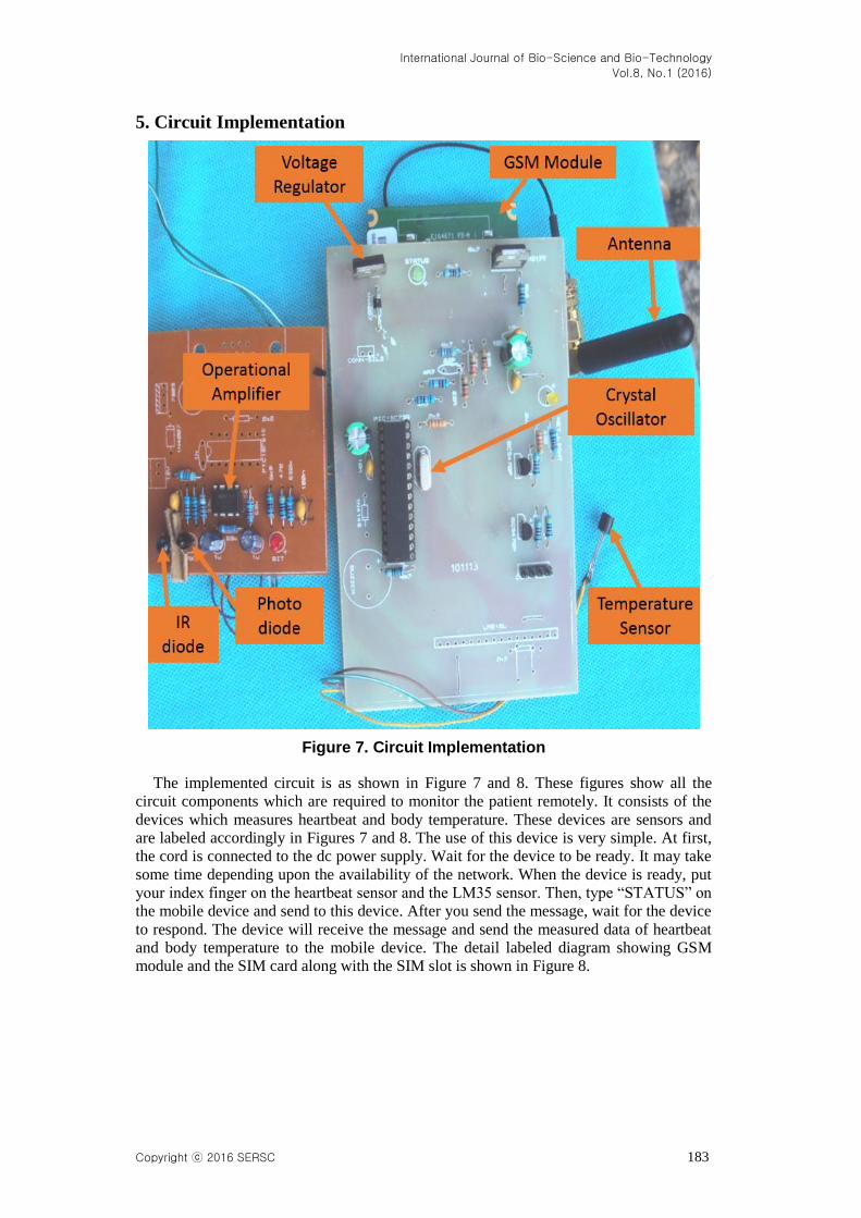
5. Circuit Implementation
Figure 7. Circuit Implementation
The implemented circuit is as shown in Figure 7 and 8. These figures show all the
circuit components which are required to monitor the patient remotely. It consists of the
devices which measures heartbeat and body temperature. These devices are sensors and
are labeled accordingly in Figures 7 and 8. The use of this device is very simple. At first,
the cord is connected to the dc power supply. Wait for the device to be ready. It may take
some time depending upon the availability of the network. When the device is ready, put
your index finger on the heartbeat sensor and the LM35 sensor. Then, type “STATUS” on
the mobile device and send to this device. After you send the message, wait for the device
to respond. The device will receive the message and send the measured data of heartbeat
and body temperature to the mobile device. The detail labeled diagram showing GSM
module and the SIM card along with the SIM slot is shown in Figure 8.

International Journal of Bio-Science and Bio-Technology
Vol.8, No.1 (2016)
184 Copyright ⓒ 2016 SERSC
Figure 8. Circuit Implementation Showing Sim Slot
6. Result and Discussion
The output from sensor and amplifier circuit was connected to the microcontroller. The
observed output signal was periodic ac signal with amplitude varying from peak to peak
according to person. A model sinusoidal signal and the output from sensor were fed to
microcontroller and the counted pulse rate was successfully sent via GSM module. The
counted signal from the sensor to measure the heartbeat was relatively a weak signal
which needed to be amplified and filtered before it was sent to the microcontroller. So,
the signal was amplified using an operational amplifier. LM328 was used to amplify the
signal. The amplified signal was then filtered to get the desired output of heartbeat which
was then sent to the microcontroller for further processing. The microcontroller then sent
the received data of both heartbeat and temperature of a patient to a remote end via GSM
module. The output is received on the Nokia N72 device. As shown in Figure 9, the
output consists of the data from sensors. It provides the data of heartbeat and body
temperature which was found out to be 76 bpm and 36.2oC respectively. Also, the
measured heartbeat and temperature for different individuals vary depending upon their
age-group. The data of heartbeat and body temperature of an individual was sent to a
mobile device and is shown in Figure 9.

International Journal of Bio-Science and Bio-Technology
Vol.8, No.1 (2016)
Copyright ⓒ 2016 SERSC 185
Figure 9. Output received on Nokia N72 mobile device
It can store a large number of data showing times and dates of the data taken for future
reference as shown in Figure 9. The storage depends upon the space available in the
memory card to store the data. A SMS takes about 4 KB space on a memory card. So, a
memory card of 512 MB will be able to store about 1,31,072 messages. The messages
will show both the date and time, so it will be easy to distinguish among the messages
according to day, week or month.
Figure 10. Heartbeat of Patients According to Age
International Journal of Bio-Science and Bio-Technology
Vol.8, No.1 (2016)
186 Copyright ⓒ 2016 SERSC
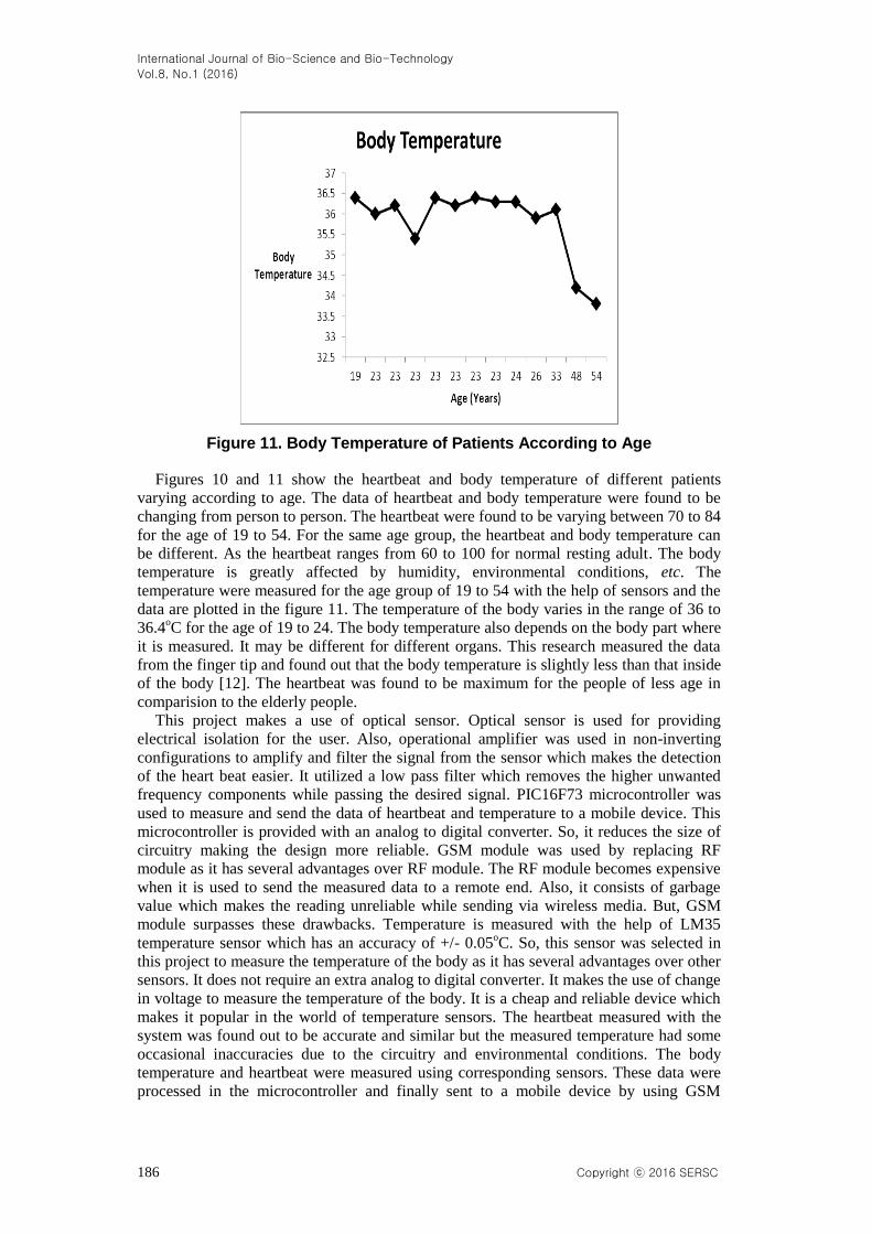
Figure 11. Body Temperature of Patients According to Age
Figures 10 and 11 show the heartbeat and body temperature of different patients
varying according to age. The data of heartbeat and body temperature were found to be
changing from person to person. The heartbeat were found to be varying between 70 to 84
for the age of 19 to 54. For the same age group, the heartbeat and body temperature can
be different. As the heartbeat ranges from 60 to 100 for normal resting adult. The body
temperature is greatly affected by humidity, environmental conditions, etc. The
temperature were measured for the age group of 19 to 54 with the help of sensors and the
data are plotted in the figure 11. The temperature of the body varies in the range of 36 to
36.4oC for the age of 19 to 24. The body temperature also depends on the body part where
it is measured. It may be different for different organs. This research measured the data
from the finger tip and found out that the body temperature is slightly less than that inside
of the body [12]. The heartbeat was found to be maximum for the people of less age in
comparision to the elderly people.
This project makes a use of optical sensor. Optical sensor is used for providing
electrical isolation for the user. Also, operational amplifier was used in non-inverting
configurations to amplify and filter the signal from the sensor which makes the detection
of the heart beat easier. It utilized a low pass filter which removes the higher unwanted
frequency components while passing the desired signal. PIC16F73 microcontroller was
used to measure and send the data of heartbeat and temperature to a mobile device. This
microcontroller is provided with an analog to digital converter. So, it reduces the size of
circuitry making the design more reliable. GSM module was used by replacing RF
module as it has several advantages over RF module. The RF module becomes expensive
when it is used to send the measured data to a remote end. Also, it consists of garbage
value which makes the reading unreliable while sending via wireless media. But, GSM
module surpasses these drawbacks. Temperature is measured with the help of LM35
temperature sensor which has an accuracy of +/- 0.05oC. So, this sensor was selected in
this project to measure the temperature of the body as it has several advantages over other
sensors. It does not require an extra analog to digital converter. It makes the use of change
in voltage to measure the temperature of the body. It is a cheap and reliable device which
makes it popular in the world of temperature sensors. The heartbeat measured with the
system was found out to be accurate and similar but the measured temperature had some
occasional inaccuracies due to the circuitry and environmental conditions. The body
temperature and heartbeat were measured using corresponding sensors. These data were
processed in the microcontroller and finally sent to a mobile device by using GSM
International Journal of Bio-Science and Bio-Technology
Vol.8, No.1 (2016)
Copyright ⓒ 2016 SERSC 187
module. It uses wireless communication to send the data which was preferred over the
wired communication as it provides a greater mobility to the device. The cost is also
minimized by utilizing the feature of sending multiple parameters via a single SMS. As
employing the device with GSM module has several advantages than employing the
device with any other system, it is wise to implement the device with GSM module for
several purposes.
7. Conclusion
This research led to the development of a system which measured heartbeat and
temperature of a patient and sent it to a remote end by the use of a microcontroller at a
reasonable cost with great effect. It utilized remote patient monitoring system technology
which enabled the monitoring of patients outside of clinical settings and leads to
increasing access to health care as well as decreasing the health care delivery costs.
Nowadays, most of the systems work in offline mode. The research utilized two sensors
for measuring heartbeat and temperature of a body. These sensors are controlled by the
microcontroller. For measurement of heartbeat, we used fingertip to measure it accurately.
The device uses the optical technology to detect the flow of blood through the finger. The
heart beat monitor in our research counts the heart beat rate in beats per minute (bpm) for
specific interval and transfers the calculated rate via GSM module and sends it to a
remote end where it displays the observed data in a mobile display. Optical sensor with
combination of infrared light emitting diode (IR LED) and IR photodiode senses the
pulse rate that produces weak output of analog signal. The signal is then amplified and
filtered and fed to the microcontroller input. The microcontroller processes the input and
calculates heart beat rate in beats per minute. Thus, calculated heart beat rate is displayed
in liquid crystal display (LCD). The data is also displayed on the screen of a mobile
device by using GSM module. LM35 is used as a temperature sensor in this project
which measures the temperature of the body and the measured data is fed to the
transmitter module. Wireless system is used to transmit the measured data to a remote
location. The transmitter transmits the calculated beat rate and is received in another
terminal called receiver module. Inconvenience of using wire is avoided in this research.
Finally, the data are displayed in the mobile screen at the receiving end where the
specialist or physician can analyse the data and will be able to provide aid. The developed
system is reliable, economical and user friendly. Though, there are certain limitations and
advantages of the system whether it is implemented with RF module or GSM module.
The RF module worked only for limited range. The specification stated that it would work
for about 100m in an open space but our research found out that it worked only for about
14m with occasional inaccuracies and sometimes the signal was hard to catch. GSM
module surpasses this drawback as it could send data to any location where network was
available. The RF module had another serious disadvantage of initial cost. The initial cost
of setting up the device with RF module is very high compared to GSM module which
has low initial cost as it requires only a GSM module and a mobile device. However, the
running cost of RF module was found out to be very low compared to GSM module. The
GSM module requires a SMS to be sent to a mobile device which may require paying for
SMS to the mobile operator unless the government takes an initiative to make the service
free of charge which would increase the reliability of the device. The RF module requires
a license after certain range from the government depending upon the geographical
location while GSM module does not require license. The license needs to be purchased
which adds the cost to the system implemented with RF module. The RF module does not
require a SIM card whereas GSM module requires a SIM card. The RF module does not
depend on the network of mobile operator while GSM module depends on it. The RF
module uses wireless serial data link while GSM module uses mobile phone protocol.
Once the device is set up with RF module, there is no need to pay any extra cost (meaning

International Journal of Bio-Science and Bio-Technology
Vol.8, No.1 (2016)
188 Copyright ⓒ 2016 SERSC
the running cost is very low, almost free). Both the device can be used according to the
need of the people. The systems are reliable, economical and user-friendly. In future,
work can be done for miniaturization of this device which will reduce discomfort and
make this device more reliable and user-friendly.
References
[1] G E. Billman, “Heart Rate Variability-A Historical Perspective”, Frontiers in Physiology., vol. 2,
(2011), pp. 1-13.
[2] J. B. Rubin and W. B. Borden, “Coronary Heart Disease in Young Adults”, Curr. Atheroscler Rep., vol.
14, no. 2, (2012), pp. 140-149.
[3] E. Jovanov, A. Milenkovic, C. Otto and P. A. Groen, “A Wireless Body Area Network of Intelligent
Motion Sensors for Computer Assisted Physical Rehabilitation”, J. Neuroeng. Rehabil., vol. 2, (2005).
[4] A. B. Donnersberger, “A Laboratory Textbook of Anatomoy and Physiology”, Jones and Bartlett
Publishers, Illinois, (2009).
[5] D. Mukherjee, K. Gupta, M. Pandey and A. Agrawal, “Microcontroller based Cardiac Counter System,
International Journal of Engineering, Applied and Management Sciences, vol. 2, (2013).
[6] L. Eisman, “Biology and Human Progress”, Englewood Cliffs, NJ: Prentice hall, (1972).
[7] L. Simmers, “Diversified Health Occupations”, Canada: Delmar, (1988).
[8] R. Trivedi, G. Mathur and A. Mathur, “A survey on Platinum Temperature Sensor”, International
Journal of Soft Computing and Engineering, vol. 1, (2011).
[9] C. K. Das, M. W. Alam and M. I. Hoque, “A Wireless Heartbeat and Temperature Monitoring System
for Remote Patients”, International Conference on Mechanical Engineering and Renewable Energy,
Chittagong, Bangladesh, (2013) May 1-3.
[10] M. S. Alam, M. W. Alam and T. Sultana, “RFID based Room Automation”, International Conference on
Mechanical Engineering and Renewable Energy, Chittagong, Bangladesh, (2013) May 1-3.
[11] T. Wellem and B. Setiawan, “A Microcontroller-based Room Temperature Monitoring System”,
International Journal of Computer Applications, vol. 53, (2012).
[12] S. Mada and S. Sandhyarani, “An Adaptive Embedded System for helping Patients”, International
Journal of Computer Trends and Technology, vol. 2, (2011).
Authors
Mohammad Wajih Alam, He received his B.Sc. degree in
Electrical and Electronic Engineering from Chittagong University of
Engineering and Technology (CUET), Bangladesh. He received BK
21 plus scholarship for his excellent academic performance.
Currently, he is completing his M.Sc. degree from University of
Ulsan, South Korea. His research interest includes Embedded
Systems, PET/MRI, Image Processing, Biomedical Engineering,
Sensors, Renewable Energy, Power System and Artificial
Intelligence.
Tanin Sultana, She received her B.Sc. degree in Electrical and
Electronic Engineering from Chittagong University of Engineering
and Technology (CUET), Bangladesh. Currently, she is working as a
lecturer at East Delta University, Chittagong. Her research interest
includes Embedded Systems, MRI, Image Processing, Biomedical
Engineering, Sensors, Renewable Energy, Power System and
Artificial Intelligence.

International Journal of Bio-Science and Bio-Technology
Vol.8, No.1 (2016)
Copyright ⓒ 2016 SERSC 189
Mohammad Sami Alam, He received his B.Sc. degree in
Electronics and Communication Engineering from Lovely
Professional University, India. He has received prestigious
scholarship during his undergraduate studies. His research interest
includes Embedded Systems, Wireless communication, VLSI, Image
Processing, Biomedical Engineering, Sensors.

International Journal of Bio-Science and Bio-Technology
Vol.8, No.1 (2016)
190 Copyright ⓒ 2016 SERSC