A GUIDE TO THE DESIGN, SPECIFICATION & CONSTRUCTION OF ... · PDF fileA GUIDE TO THE DESIGN,...
62
A GUIDE TO THE DESIGN, SPECIFICATION & CONSTRUCTION OF MULTI USE GAMES AREAS (MUGAs) INCLUDING MULTI-SPORT SYNTHETIC TURF PITCHES (STPs) Part 3 (of 3) – General Conditions and Preliminaries; Design and Construction Requirements & MUGA Specific Requirements Produced by Sport England, in conjunction with the Sports and Play Construction Association. For info or comments please email [email protected] 1
Transcript of A GUIDE TO THE DESIGN, SPECIFICATION & CONSTRUCTION OF ... · PDF fileA GUIDE TO THE DESIGN,...
A GUIDE TO THE
DESIGN, SPECIFICATION
& CONSTRUCTION
OF
MULTI USE GAMES AREAS (MUGAs)
INCLUDING
MULTI-SPORT SYNTHETIC TURF PITCHES
(STPs)
Part 3 (of 3) – General Conditions and Preliminaries; Design and Construction Requirements & MUGA
Specific Requirements
Produced by Sport England, in conjunction with the Sports and Play Construction Association.
For info or comments please email [email protected]
1

GENERAL CONDITIONS AND PRELIMINARIES
Contents Page SECTION 1 • Information to be read before completing General Conditions and
Preliminaries 4 • Index
1. Project Particulars 5 2. Tender and Contract documents 5 3. The Site/Existing Buildings 6 4. Description of the project 8 5. Contract details 8 6. Tendering/Subletting 8 7. Provision, content and use of documents 9 8. Management of the project 10 9. Quality standards/Control 12 10. Security/Safety/Protection 14 11. Specific limitations on Methods/Sequence/Timing 16 12. Facilities/Temporary Work/Services 17 13. Operation/Maintenance of the finished building 18 14. Contractor’s general cost items: Site accommodation/Services and facilities/Mechanical Plant/Temporary Works 18 15. Other Clauses 19
For info or comments please email [email protected]
2

Page SECTION 2 – DESIGN AND CONSTRUCTION REQUIREMENTS 20
2.01 Design and Performance Criteria 20 2.02 Construction 20 2.03 Fencing 22 2.04 Floodlighting 24 2.05 Sports Equipment 27 2.06 Reinstatement 27
• Appendix A: MUGA Specific Requirements 30 • Appendix B Site Specific Requirements 58 • Appendix C Typical generic product specifications 60 • Acknowledgements 62
For info or comments please email [email protected]
3
Information to be Read Before Completing General Conditions and Preliminaries Please note that the disclaimer, which appears at the start of Part 1 of this guidance note, equally applies to this Part 3. Applicants should choose a procurement method and form of contract, which best suits their own project and is in line with Government’s procurement and design advice. (Please refer to guidance on procurement). These general conditions and preliminaries are intended to act as a guide only and are not intended to be compulsory or prescriptive. The draft preliminaries and general conditions do not favour any one form of contract. The following words are used throughout this document:
• “Contractor” to mean the successful tender who will complete the design or the construction of the project
• “Employer” to mean the person who has commissioned and is responsible for the project.
• “Works” to mean the works described in the form of contract and shown upon or described or referred to in the contract documents.
• “Test House” to mean the Laboratory appointed by the Employer to undertake independent testing during construction at completion and during defects maintenance period.
This document must be read in conjunction with other Parts (1 & 2) of the Guide to the Design, Specification and Construction of Multi Use Games Areas including Multi-Sport Synthetic Turf Pitches.
For info or comments please email [email protected]
4
SECTION 1 - GENERAL CONDITIONS & PRELIMINARIES
1. Project Particulars (The project particulars will usually detail a brief
project description, the parties to the contract and members of the design team)
The Project: [***Complete as appropriate] Name: Nature: Location: Timescale for completing the works:
Name of Employer [*** Complete as appropriate] Address: Tel: Fax: Email:
Name of Contractor: [*** Complete as appropriate] Address: Tel: Fax: Email:
Members and details of the Design Team: [*** Complete as appropriate]
Name of Test House [*** Complete as appropriate] Address: Tel: Fax: Email:
2. Tender and Contract documents. (NB: The information contained in this section will depend on the Employer’s tendering instructions. This section includes details of the tender and contract documents)
The tender drawings are: all as listed in [***Complete as appropriate]
The contract drawings are: all as listed in or alternatively will be developed at a later stage [*** Complete as appropriate]
For info or comments please email [email protected]
5
Other contract documents – Specification ***The specification should be based on the requirements of Appendix A (MUGA Specific Requirements) and the project specific information as detailed in Appendix B. An appropriate qualified professional person must prepare the project specification. Please refer to Part 1 Section 7, (Professional Services) contained in the Guide for Design Specification and Construction of MUGAs including multi sport STPs.
***Planning Permission ***Site investigation Report and Topographical Survey (The provision of this document is deemed as essential to ensure meaningful tenders are obtained and therefore encourage a greater degree of cost certainty). ***Party wall awards and notices ***Pre-tender Health and Safety plan ***Other documents which the Employer’s design team deem as appropriate
3. The Site/Existing Buildings
(This section includes details of the site and existing building) The Site: As defined on drawing nr [*** Complete as appropriate] Existing Mains/Services: All as shown / defined on drawing nr [***Complete as appropriate] Soil and ground water information: Details are given in [***Complete as appropriate] Topographical Survey: Details are given in [***Complete as appropriate] Site investigation: Details are given in [*** Complete as appropriate.] It is the responsibility of the Contractor to satisfy himself as to the completeness of Employer’s Ground Investigation Report to ensure adequate knowledge of the nature of the existing ground, and its bearing capacity and to allow the required sub-base design for the project. The responsibility for the sub-base and drainage design lies entirely with the Contractor and no increase in the tender price or subsequent Contract Sum will be allowed for any costs of whatever nature. [This
For info or comments please email [email protected]
6

clause may be amended depending on the form of contract used and the Employer’s risk management strategy]. On the award of the contract the successful Contractor will have been deemed to have undertaken any additional site investigations they consider necessary. No claims will be accepted for lack of information or inaccuracies in this respect. [This clause may be amended depending on the form of contract used and the Employer’s risk management strategy]. Disposal of spoil and arisings: [This clause shall detail the arrangements for disposal of spoil and arising, including the removal from site to licensed tips and any landscape works on site, etc] Access to the site: All as defined on drawing nr [***Complete as appropriate] Access (including deliveries of goods and materials) to the site will not be permitted during the hours of [***Complete as appropriate], considering peak traffic movements around site and adjoining areas. Parking of the Contractor’s employee’s vehicles: Will be restricted to areas indicated on drawing nr [*** Complete as appropriate] Use of site: [***Amend as appropriate] do not use the site for any proposes other than carrying out the Works. Advertisements: [***Amend as appropriate] All rights of advertising on the site shall be reserved by the Employer and Funding Agencies. The Contractor shall take all necessary measures to ensure that no unauthorised advertising takes place.
Publicity: [***Amend as appropriate]: No information, either written or verbal, nor photography or drawings concerning the Contract shall be supplied by the Contractor to any persons without the written authority of the Employer. Surrounding Land /Building uses: All as defined on drawing nr [***Complete as appropriate]
Site visit may be made by arrangement with [***Complete as appropriate]
NB: The above list is not to be considered as exhaustive and any other comments relevant to this section, which are deemed as appropriate should be included.
For info or comments please email [email protected]
7
4. Description of the project
Preparatory works by others: [*** Complete as appropriate] Description of the project: [***Complete as appropriate] Schedule of intended use (sports and intensity of use) Work by other concurrent with the contract: [***Complete as appropriate] Completion work by others: [***Complete as appropriate]
NB: The above list is not to be considered as exhaustive and any other comments relevant to this section, which are deemed as appropriate should be included.
5. Contract details
The Contractor shall agree to undertake to enter into a formal contract [***Complete as appropriate]. NB: The form of contract should be detailed out and the contract clauses intended to be used, included in this section and fully completed. Where an Employer has considered that their preferred form of contract is design and build/develop and construct, they should ensure that the Contractor shall assume full responsibility for the preparation of the design, and for the construction of the whole of the project as described in the Employer’s Requirements.
It is recommended that the defect maintenance period for MUGAS and STPs is twelve months.
6. Tendering/Subletting (NB: The information contained in this section
will depend on the Employer’s tendering instructions).
Conditions of Tendering: Should take into consideration the following • Any conditions of tendering or procurement stipulated by the
funding agencies [***Complete as appropriate] • The Employer does not bind itself to accept any design or tender. • Contractors tendering do so at their own cost • Tenders shall remain open for acceptance for a period of twelve
[***amend if appropriate] weeks after the due date for submission.
• The items as listed in Appendix B of this document.
8
• Attend an interview at the Employer’s office to explain their tender proposals. This will include the methods of construction, the
For info or comments please email [email protected]

construction programme and management structure to be used to control and progress the works.
• ***The Contract Sum is a fixed price and will not be subject to any adjustments save only in respect of any provisional or prime cost items or where the Employer shall have issued a written change in design instruction. [***Please amend as appropriate to reflect the form of contract and/or the Employer’s risk management strategy including sharing of savings achieved.]
• ***By submitting a tender the Contractor agrees that should obvious errors in pricing or errors in arithmetic be discovered before acceptance of his offer in the Tender Sum Analysis, the errors shall be corrected in accordance with Alternative 2 contained in Section 10 of the NJCC “Code of Procedure for Tendering for Design and Build” dated March 1996. [***Please amend as appropriate if Employer has alternative arrangements]
• The Contractor shall further agree that until this tender is incorporated in such a formal contract, executed under deed by the Employer, this tender together with written acceptance thereof will constitute a binding contract.
• Master Design [where appropriate] and Construction Programme: The Contractor shall prepare and submit their proposed programme for the execution of the works for comment by the Employer.
• The inclusion of “listed” domestic sub-contractors and associated relevant tender information can be included in this section.
• Criteria for selection of successful tender • Confirming to remaining tenders why their bid was not
successful NB: The above list is not to be considered exhaustive. The Employers attention is drawn to timescales required for the agreement and approval of external funding.
7. Provision, Content and Use of Documents
It is recommended that the appropriate clauses are included in this section:
• Definitions and Interpretations • Documents provided by the Employer • Documents provided by the Contractor/Sub Contractors/
Suppliers • As built drawings and information
For info or comments please email [email protected]
9
• Technical literature • Maintenance instructions and guarantees
NB: The above list is not to be considered exhaustive and recommend that clauses in the National Building Specification be considered in further detail.
8. Management of the project Site Administration and supervision: The Contractor shall allow for all necessary site administration and supervision for the proper execution of the Works. Prior to commencing the works on site the Contractor shall confirm to the Employer the name of the person in charge of the site together with brief details of his experience. This person is not to be changed without the prior agreement of the Employer, which shall not be unreasonably withheld. Insurance: The Contractor shall ensure that the works and the site are properly protected and secured at all times, including any works outside the site boundary, and that the Employer is indemnified against any claim for loss, damage, theft or the like. Statutory Regulations: The Contractor shall allow for complying with any such regulations or requirements concerning pedestrian or vehicular traffic control, the loading and unloading of or waiting by vehicles on the public highway, site ingress and egress, safety precautions and other matters affecting the works.
Planning Consent & Building Regulations Approval: ***The Contractor is to allow for any necessary liaisons with the relevant planning authority, and for complying with any requirements of the planning authority, as advised by the Employer at the time of Tendering. [***Amend as appropriate to reflect Employer’s approach to risk management in respect of Planning Consent & Building Regulations Approval.] The Contractor shall obtain any necessary statutory formal approvals for the works, as advised by the Employer at the time of Tendering. [***Amend as appropriate.]
The Construction (Design and Management) Regulations 1994:This Contract will be executed strictly in accordance with the Regulations. ***The Contractor named in the articles of agreement of the chosen form of contract will be deemed the Principal Contractor. [***Amend as appropriate.] The Contractor shall
For info or comments please email [email protected]
10

• Submit the Construction Phase Health and Safety Plan for the project on [within agreed timescale] and shall execute the whole of the Contract strictly in accordance with this.
• Allow the Planning Supervisor access to the Works and afford them every reasonable facility for the performance of their duties.
• Co-ordinate with the Planning Supervisor, execute the Health and Safety Plan and contribute as required to the Health and Safety File.
• Allow for compliance with the requirements to fulfil the pre-tender and construction phase Health and Safety Plans.
NB: The above list is not to be considered exhaustive.
***Design and Construction Programme: Thereafter the Contractor shall amend and revise the programme as required by the Conditions of Contract or as requested by the Employer. The programme shall be represented on a bar chart showing each primary stage of construction or [***alternative format to be agreed with the Employer]. When updated this shall show the percentage of works completed up to the dating of reporting. [***Amend as appropriate]
Method Statement: The Contractor should provide, at the time of tendering, a statement describing their proposed general and detailed arrangements and methods for carrying out the works. The Method Statement should include the following:
• How all stages of the works will be executed • Procedures to ensure the specified parameters are obtained • The appropriate climatic conditions in which the surfacing can
be laid • The appropriate Health and Safety requirements and training
those personnel will undergo prior to working on site. • Indicate areas of work that will be sub-contracted and detail the
company(s) that will be employed. NB: The above list is not to be considered exhaustive.
Site meetings: The Contractor will ensure the following
• Provision of accommodation [unless to be provided by the Employer] for site meetings every [*** interval to be advised]
• Two [***amend if required] set of colour site photographs [*** size to be advised]
• Attend all meetings and advise subcontractors or suppliers when their presence is required
• Progress statement by reference to the design and construction Master programme
For info or comments please email [email protected]
11

NB: The above list is not considered to be exhaustive.
The [***person to be nominated] will chair the meeting and distribute meetings. Control of cost: Include clauses here, which are appropriate for control of costs e.g. cash flow forecast, interim valuations, unfixed materials materials off site, etc. In the event that the Employer decides to pay for materials off site, they are recommended to ensure adequate protection is in place to safeguard title to the materials or goods. NB: The above list of clauses is not to be considered exhaustive.
9. Quality standards/Control Supervision, inspections & sampling: Where the Contractor has given notice [***insert details of minimum days required] of that a particular operation or stage of the works will be ready for inspection by the Employer and they then find that the works are not complete on that date so that the inspection cannot be carried out or completed necessitating a further visit, the additional cost incurred, including all expenses, will be borne by the Contractor. The Employer or their representative including the Test House will take samples of all materials and have them tested for compliance with the Contractor's tender submission and this document. Test methods to be employed will be in accordance with current practice. The Contractor shall allow for the taking of such samples and the proper recording of the location to which the samples relate, as directed by the Employer and detailed in the documents [***identify location]. Samples for test shall be delivered within 48 hours of being instructed by the Employer. Any delay to a scheduled inspection or preparation of a report by the Test House arising from late delivery of the samples for test or from failure to keep proper records as required, shall not relieve the Contractor from his responsibility with regard to completion within the Contract Period.
Failure of tests Defective work: Should any samples or intermediate stages of construction tested be found, in the opinion of the Employer, to be unsatisfactory or likely to produce unsatisfactory work, the defective material or the consignment which the sample represents shall be removed from the site or suitable corrective action taken, as approved by the Employer, to achieve the specified performance outcome. Notwithstanding that, any sample or intermediate work stage, which has been accepted by the Employer or their representative, may
For info or comments please email [email protected]
12

subsequently be rejected if they shall decide that the quality has in any way deteriorated.
The Contractor shall, at their own expense, remove and replace all rejected materials, or correct any intermediate work stage shown to be outside specification. Any delays consequential upon the rejection of any sample or work stage:
• Shall not in any way relieve the Contractor from their responsibility with regard to completion within the contract period
• Will not be considered as grounds for extension of time • Will be at the expense of the Contractor
Work corrected or materials replaced for these reasons will be re-checked or re-tested by the Employer or their representative. The additional costs of testing any material replaced for this reason or re-inspecting any work stage subjected to remedial works shall be recovered from the Contractor by an appropriate deduction from the contract sum.
Quality of materials and workmanship
Proposals for rectification of defective work/Products: Where and to the extent that materials, products and workmanship are not fully specified they are to be:
(i) Suitable for the purposes of the Works stated in or
reasonably to be inferred from the contract documents.
(ii) In accordance with good building and/or engineering practice, including the relevant provisions of current British Standards.
(iii) In accordance with the Code of Practice for the
Construction and Maintenance of Tennis Courts (Type 1, 2, 3 and 4 MUGAs) or the Code of Practice for the Construction and Maintenance of Artificial Grass Sports Pitches as published by the Sports and Play Construction Association (Type 5 MUGAs and STPs).
It is recommended that the appropriate clauses are included in this section:
• Checking compliance of documents and Quality of workmanship • Protection of products • Suitability of related work and conditions, water for the works etc • Procedure for approval of products and provision of samples,
and samples of finished work
For info or comments please email [email protected]
13

• Accuracy and setting out, critical dimensions, record drawings, etc
• Services regulations, services runs, mechanical and electrical services
• Work at or after completion • Security at completion • Making good defects, arrangements for access, timetable for
schedule of repairs including identification of priorities • Maintenance instructions and guarantees
NB: The above list is not to be considered exhaustive and recommend that clauses in the National Building Specification be considered in further detail.
10. Security/Safety/Protection
Pre-tender Health and Safety plan: This is a separate document to be read in conjunction [***amend as appropriate, stating which section the Plan is included] with the preliminaries and general conditions.
The Construction Phase Health and Safety plan: must be submitted to the Employer, Planning Supervisor [***include others members of the design team as appropriate] not less than [specify period] before the proposed date for start of the construction work. Do not start the construction work until the Employer has confirmed in writing that the Construction Phase Health and Safety Plan includes the procedures and arrangement required by the CDM Regulations. Trespass and Nuisance: All reasonable means shall be used to avoid inconveniencing adjoining owners and occupiers. No persons employed on the works shall be allowed to trespass on adjoining properties. The Contractor shall indemnify the Employer against any claims or action for damage on account of any trespass or other misconduct of the Contractors' employees. Site Security and Temporary Fencing: The Contractor shall provide all temporary and permanent fencing as necessary to ensure the Works remain protected from all unauthorised entry. The Contractor must provide for situating their temporary buildings and offices and the storing of materials etc. within the site boundaries [if there is alternative accommodation available, amend clauses]. The site is to be maintained in a secure state until completion at which time all temporary fencing, building materials and equipment is to be removed and all works made good. The site is also to be left in a safe and tidy state at the end of each working day.
For info or comments please email [email protected]
14

Control of Noise and Pollution: The attention of the Contractor is drawn to the provision of Section 60 of the Control of Pollution Act 1974 with references to the control of noise in relation to any construction works, and must comply therewith. The Contractor is recommended to confer with the local Chief Environmental Officer in relation to proposed method of construction and noise level. Safety, Health and Welfare of Work people: The Contractor shall allow for providing and maintaining all welfare and safety measures to a standard not inferior to that laid down in statutory instruments, rules and orders and subsequent amendments thereto for all workmen employed on the site including the employees of subcontractors.
Sanitary accommodation for workpeople and staff shall be provided, connected to existing drainage where practicable, and maintained in a thoroughly clean, deodorised and orderly condition. All huts and other temporary facilities shall be removed, and contaminated soil disinfected and all damage made good on completion of the Contract. The Contractors' attention is particularly drawn to their obligations under the Health and Safety at Work Act etc., 1974.
Maintenance of Roads, public paths, etc: The Contractor shall maintain all public and private roads, footpaths, paved areas, boundary walls and fences on or adjacent to the site in their present condition and on completion, make good any damage arising from the works and reinstate to the satisfaction of the Employer. Damage to existing property, roads etc: The Contractor is to make good any damage caused to any land, public and private roads, footpaths, services under, kerbs, paved areas, boundary walls, and fences etc. by his own and by subcontractors and suppliers plant, transport and activities, at his own expense or pay the cost and charges in connection therewith. Photographic survey: The Contractor is to carry out a photographic survey of the site boundaries, footpaths and roads and agree their condition with the Employer prior to works commencing. Storage of Materials: No storage of materials will be allowed on the adjoining roads or pavements.
Keeping Roads, etc. Clean: The Contractor shall keep any public, private and existing roads, drains, footpaths and paving on or adjacent the site or used by traffic entering or leaving the site in a clean and unobstructed and safe state to the satisfaction of the Employer, the
For info or comments please email [email protected]
15

Police and the Local Authority. The Contractor shall use all means to prevent mud or rubbish of any kind being carried on to such roads, footpaths and paving, by vehicles being used to carry out the Works to the reasonable satisfaction of the Employer. Where, however, in spite of such precautions, mud or rubbish is carried on to the roads, footpaths or paving, the Contractor shall immediately clean up such mud or rubbish at his own expense by scraping, brushing, shovelling and removing to tip. Special attention must be given to prevent mud becoming embedded in the road and footpath surfaces. Removing Rubbish etc. and Cleaning Works on Completion: The Contractor shall allow for removing all rubbish, protective casings, coverings and debris from the site. Recommend that the appropriate clauses are included in this section:
• Permitted use of explosives, pesticides • Fire protection, burning on site • Noise • Pollution • Protection of work and all parts of the works, including work
carried out by others throughout the contract • Existing services • Retained trees, shrubs, grassed area etc • Existing features, party walls and fences
NB: The above list is not to be considered exhaustive and recommend that clauses in the National Building Specification be considered in further detail.
11. Specific limitations on Methods/Sequence/Timing 11.1 Limitations of Working Space
The Contractor shall confine everything pertaining to the Contract within the area of the proposed works and as marked on drawing nr [***please complete]. The Contractors operations required to carry out the works shall be executed carefully so as to cause minimum nuisance and inconvenience to the users of adjoining facilities. Access (including deliveries of goods and materials) to the site will not be permitted during the hours of [***Complete as appropriate, considering peak traffic movements around site and adjoining areas] Work carried out by others throughout the contract: The Contractor is to allow for general attendances by representatives’ from the Test House.
For info or comments please email [email protected]
16

Recommend that the appropriate clauses are included in this section:
• Work concurrent with this contract • Work carried out by others throughout the contract • Access to the site • Party wall awards notices • Working hours ** am to *** pm, no working permitted on ***
[***Complete as appropriate] • Completion works in section or parts. [***Complete as
appropriate] NB: The above list is not to be considered exhaustive and recommend that clauses in the National Building Specification be considered in further detail.
12. Facilities/Temporary Work/Services
12.1 Site Access and Temporary Roads, Hard Standings etc: The contractor shall allow for forming a suitable site access to allow the works to be undertaken during the agreed contract period. This shall include providing all temporary roads, hard standings, crossings and the like necessary for carrying out the whole of the Works. On completion of the Works the contractor shall remove any temporary haul roads and fully reinstate access way and other disturbed areas.
Temporary Accommodation for use by the Contractor: The Contractor shall allow for providing and maintaining all necessary temporary services and offices or storage for materials for his own requirements. The accommodation will include the following items
• Telephone, [***include as appropriate]. • Facsimile machine [***include as appropriate]. • Email facility [***include as appropriate].
NB: The above list is to not to be considered exhaustive. No offices, stores or temporary buildings shall be erected on site without first obtaining the consent of the Employer as to the position in which they are to be erected.
Name Board: The Contractor shall obtain approval and provide a suitable temporary name board, displaying the following details [***to be completed] Water, lighting and power: This supply is from the Employer’s mains and may be used for the works, subject to the following conditions [***amend as appropriate]. OR Temporary water, lighting and power supplies to be arranged by the Contractor.
For info or comments please email [email protected]
17
Recommend that the appropriate clauses are included in this section:
• Beneficial use of installed systems NB: The above list is not to be considered exhaustive and recommend that clauses in the National Building Specification be considered in further detail.
13. Operation/Maintenance of the finished facility
The operation and maintenance manual (incorporating the Health and Safety File and subtitled accordingly) is to be a comprehensive information guide for the Employer and end users providing a thorough and understanding of the facility [***amend as appropriate], it’s systems which will enable it to be operated and maintained safely. The Contractor is required to
• Submit the manual at completion of the Works • Obtain or prepare all the information to be included in the
manual • Submit the manual to Planning Supervisor and [***insert as
appropriate], • Upon approval of the manual, produce [***insert as
appropriate], copies and deliver to Employer. The manual is to consist of the following details [***Complete as appropriate.] Training of Employer’s Staff: Before completion of the Works, the Contractor will explain and demonstrate to the Employer’s maintenance staff or other appointed representative, the purpose and operation of the installations systems. Allow for not less than [***Complete as appropriate] days. Spare parts: The Contractor is to submit a schedule of spare parts that should be obtained by the Employer for the maintenance of the services installation, [***insert as appropriate] NB: The above list of clauses is not to be considered as exhaustive and will vary between contracts.
14. Contractor’s cost items/ Site accommodation/Services and
facilities/ Mechanical Plant/ Temporary Works The Contractor shall allow for providing all of the following for the completion of the Works.
• Management and staff
For info or comments please email [email protected]
18

• Site accommodation • Power • Lighting • Water • Health and Safety including the Operations and Maintenance Manual • Administration costs including telephone • Cleaning • Drying out • Protection of work • Security • Testing (NB excluding testing commissioned by the Employer’s, refer
to 11.0 Specific limitations on Methods/Sequence/Timing). • Temporary works • Tools and Plant • Work/Products By/On behalf of the Employer NB: The above list is not to be considered as exhaustive and will vary between contracts.
15. Other Clauses
Include any additional clauses here.
For info or comments please email [email protected]
19

SECTION 2 - DESIGN & CONSTRUCTION REQUIREMENTS 2.01 Design & performance criteria 2.01.1 The site and project specific criteria, as detailed in Appendix B, form part
of the Employer’s Requirements. 2.01.2 The design and performance criteria of the MUGA shall be in
accordance with the relevant table detailed in Appendix A and stated in Appendix B.
2.02 Construction 2.02.1 Formation preparation The area of the works shall be stripped of all vegetation and topsoil to a
depth of at least 75mm, the exact depth being determined by reference to the trial hole logs recorded during the ground investigation survey. The ground shall be trimmed and levelled using cut and fill as required. Any filling should be carried out in layers not exceeding 150mm thickness, and each layer should be compacted before the next is spread.
Any soft spots shall be excavated and replaced with imported crushed
rock, free from detritus material, in accordance with the Department of Transport Specification for Highway Works (Class 6F1 or 6F2).
The finished formation should be trimmed to a tolerance of ±25mm and
have a minimum undrained shear strength of at least 50kN/m2 or a California Bearing Ratio of (CBR) 2%.
The prepared formation shall be treated with a total weed-killer selected
to minimise the risk of future weed growth within the construction. The form of weed killer to be used shall be detailed in the Contractor’s Proposals and it shall be applied strictly in accordance with the manufacturer’s specified application rate.
A geotextile membrane shall be laid over the formation. Joints shall
overlap by at least 300mm. 2.02.2 Drainage The Contractor shall design and install a closely spaced system of
surface water drains that will: (i) Protect the installation from the effects of ground or surface water
For info or comments please email [email protected]
20

from the areas surrounding the MUGA / STP. (ii) Ensure that all surface water shall be removed from the site at the
rate of porosity specified for the surface to ensure that no surface flooding will occur during heavy storms, or the facility will not be lost either through rain at the highest intensity which may be expected to occur once every five years or through continuous rainfall of 50mm over a 24 hour period.
(iii) Ensure no water remains present in the construction so that it
may result in a reduction of the load bearing capacity of the formation or in any frost damage to the constructions.
Drainage works should be undertaken in accordance with the
Landscape Association’s Code of Practice for Drainage Works and the relevant clauses of the ‘Drainage’ requirements of the Department of Transport Specification for Highway Works.
Drainage trenches shall be a minimum of 450mm deep from formation
by 300mm wide and contain 100mm (minimum diameter) perforated-plastic drainage pipe in accordance with BS 4962. Trenches shall be back filled with clean graded round/sub-rounded gravel or Lytag. All drainage pipes shall be laid to a minimum fall of 0.5%.
Rodding eyes, with cast iron covers, shall be installed at each corner of
the MUGA / STP. Any existing drains cut through during the construction of the MUGA
shall be re-connected into the new system. 2.02.3 Perimeter Edgings The Contractor shall design and install edging details at the abutment
between the playing surface and the surrounding margin such that they facilitate the maintenance of the playing surface and surrounding areas, but minimise the risk of mechanical damage to or contamination of the playing surface from the maintenance of the adjoining surfaces and present no trip or void.
Edgings shall comprise precast concrete kerbs or other approved
edgings. They shall be haunched in concrete in accordance with the Department of Transport Specification for Highways Works. The maximum gap between the outer kerb face and adjacent perimeter fencing shall be 10mm. The haunching shall incorporate movement joints at appropriate spacings.
For info or comments please email [email protected]
21

2.02.4 Foundations The Contractor shall design and install a sub-base to the MUGA / STP
that shall (i) Resist the effects of frost or drought that may be expected to
occur in a return cycle of 50 years (ii) Provide stability to the finished surface such that in use it shall not
move outside the tolerances for surface regularity over a period of 10 years
The depth of the sub-base shall be determined by the contractor to satisfy the specified design criteria and taking into account the findings of the ground investigation survey. In all cases the depth shall be equal to or greater than the minimum requirements of Clause 1.6 of the Code of Practice for the Construction and Maintenance of Tennis Courts for Types 1, 2, 3, 4 and 5 MUGAs or Clause 1.5 of the Code of Practice for the Construction and Maintenance of Artificial Grass Sports Pitches for STPs.
The sub-base shall be laid and compacted so the in-situ density shall be
not less than 95% of the maximum dry density when tested in accordance with BS 1377 part 4 (2.5kg method). Consolidation shall be roller of equal or greater weight than that used to consolidate the overlying macadam layers.
2.02.5 Macadam binding (base) course & surfacing (wearing) course
The macadam binding and surfacing courses shall be produced and laid in accordance with clause 3.1.2 and 3.1.3 of the Code of Practice for the Construction and Maintenance of Tennis Courts for Types 1, 2, 3 and 4 MUGAs or Clause 1.7.1 sub-clause (i) of the Code of Practice for the Construction and Maintenance of Artificial Grass Sports Pitches for Type 5 MUGAs and STP.
2.02.6 Surfacing
The surfacing shall be in accordance with the relevant specific requirements of Appendix A.
2.03 Fencing All fencing works shall be undertaken in accordance with the appropriate
sections of BS 1722. Unless specified otherwise mesh shall be 50mm square weld mesh, corner posts shall be hollow section measuring
For info or comments please email [email protected]
22

60mm x 60mm x 3mm and intermediate posts shall measure 60mm x 40mm x 3mm. All posts shall be set in concrete footings. Heights shall be as detailed by the Employer. All mesh and posts shall be galvanised in accordance with BS EN ISO 1461. Welded mesh fences shall conform to BS 443.
Top bracing rails shall be fitted to all fencing. Post caps shall be fitted to tops of all hollow section posts . Where required, powder coating shall be in accordance with BS EN
6497 On low level fencing no ends of mesh or wire shall cause hazards to
players, particularly children. There shall be no protruding fence (or other) fixings within the MUGA / STP. All fixing bolts shall be assembled with heads inside and bolts trimmed to within 6mm of the nut. The trimmed ends should be burred and treated or shear head nuts used.
Single gates shall be at least 1.2m wide. Gates in high fencing shall
have a lintel above to the fence height. All gates shall be hung plumb, level and secure for full opening without interference. Gate lathes shall include provision for padlocks. Gate hinges shall permit gates to open outwards through 180° and have stops to prevent reverse opening. Bolts on gates shall be captive and lockable both shot and withdrawn. Bolt sockets shall be set in concrete.
Dog or anti-contamination grids shall be installed at all entrances. On MUGA Types 4 and 5 and STPs the base of the perimeter fencing
shall be fitted with rebound boards or kick boards as specified by the Employer.
Kick boards shall be nominal 250mm high x 50mm thick, pressure
treated (in accordance with BS 5589 category A [40y]) weather resistant smooth planed timber with chamfered top edge, the sections of which shall be bolted to, and jointed only at, the fence posts or intermediate stub posts. Split boards will not be accepted.
Rebound boards shall be 1.2m high by at least 12mm thick,
homogenous resin based exterior grade boarding. Colour as specified by the Employer. Evenly spaced vertical expansion gaps shall be left between adjacent boards, in accordance with the manufacturer’s recommendations. Unless otherwise boards shall be mounted to twin
For info or comments please email [email protected]
23

welded flats mounted to line posts and steel section angle support rails. Mesh shall be taken behind kick boards / rebound boards and attached
to prevent hand traps. 2.04 Floodlighting 2.04.1 Design criteria The Contractor shall design supply and install a floodlighting system to
the MUGA to meet the requirements set out in Appendix A, Tables 1 to 5 as appropriate and in full compliance with the planning approval for the facility.
The works shall include the provision of all luminaries, columns, mains
distribution switch gear, sub-circuit protective devices, metering and control devices and the associated cabling, trenching, ducting & draw pit installation, back filling and making good.
All works shall be carried out in accordance with the latest edition of the
IEE wiring regulations.
For courts, the illumination standard is applied to the individual Principle Play Areas within the MUGA For pitches the illumination standard applies to the Principle Play Area of the pitch. The following standards shall apply to all lighting designs
Property Requirement Overall minimum maintenance factor
0.80
Glare rating (Gr) <50
Colour rendering value (Ra) > 65
Colour temperature (K) > 4000 2.04.2 Column bases The Contractor shall take full account of the ground conditions, as
detailed in the ground investigation survey report, when designing the bases for the floodlighting columns.
For info or comments please email [email protected]
24
Base plates shall be arranged to ensure all fixing bolts are concealed
and cannot constitute a trip hazard. 2.04.3 System Protection System protection shall include Mccbs, rated for the prospective load of
the proposed installation and selected to match the required fault level. The arrangement of the power distribution at the distribution point shall
provide for short circuit and excess current protection for all sub-circuits. Adequate discrimination between main Mccb and sub-circuit protective devices shall be included.
2.04.4 Power Cables
The cabling at the central distribution point and to the columns shall be carried out in correctly sized XPLESWA cables.
2.04.5 Control cable
All necessary control cables are to be included for the connection of controls within the column gear trays to the main switchgear position.
2.04.6 Earthing
All necessary earthing and cross bonding shall be provided in accordance with the current edition of the IEE wiring Regulations.
2.04.7 Ducting Cable ducting shall be installed so, in conjunction with draw pits, it
provides an underground containment system in all hard landscaping to allow the future re-cabling of the lighting system. Unless otherwise specified ducting shall comprise 100mm diameter minimum rigid plastic ducting pipe, with flexible ducting where necessary. All ducting shall be buried to a minimum depth of 450mm and cable warning marker tape shall be laid 150mm above all ducting. Service ducting and draw pits for electric cables shall include for the provision and installation of draw ropes.
2.04.8 Draw pits Draw pits shall be installed at each floodlight column and at all changes
of direction. They shall be pre-formed, be a minimum of 450 diameter or 450mm by 450mm square and have lockable removable lids. They shall
For info or comments please email [email protected]
25

be installed prior to the installation of the ducting. Where stacked plastic sectional draw pits are used the duct entries shall be drilled to avoid weakening of the structure.
2.04.9 Cables in soft ground
Cables in the soft ground shall be buried in trenches to a minimum depth of 500mm. Where applicable (as detailed in the IEE Wiring Regulations) cables shall be laid on a bed and surround of sand 150mm thick. Buried cables shall be identified along their entire length in service trenches with yellow marker tape installed 150mm from ground level. The marker tape shall labelled “ DANGER – ELECTRIC CABLE BELOW”
2.04.10 System Management Individual Mccb protection shall be provided for each control circuit. A master time clock with battery back-up shall be provided to cut-out the
floodlights at the programmed time. The clock shall allow for the seasonal changeover from GMT to BST. A key switch for manual override shall also be provided.
To allow safe egress at the cut-off time, at least one luminaire on each
operational portion of the MUGA / STP shall remain in operation for a five minutes period following cut-off.
The management system shall include a system of visual warning to
warn users the cut-off time is approaching. This shall be achieved by switching a flashing beacon(s). The beacon shall operate five minutes before the cut-off time. It shall only operate if any element of the floodlighting is in use.
A set of manual override switches shall be provided for test and
emergency control of the lights. A Kwhr meter shall be provided to monitor the total power used by the
floodlights. An ‘hours run’ facility shall be provided to identify the cumulative time
each group of floodlights serving the MUGA / STP has been in operation.
2.04.11 Small power
For info or comments please email [email protected]
26

Single socket outlets, common key controlled and RCD protected, shall be provided to at least two columns (or more if specified by the Employer). Each shall be terminated either within the base of the column or finished with the cover flush with the fence or rebound boards. The fitting shall be of a proprietary make and, where applicable, weatherproof.
2.05 Sports Equipment The Contractor shall supply and erect sports equipment and fixtures as
detailed in Appendix B. All equipment shall be in accordance with the relevant rules of the sport and comply with all relevant British Standards.
Football goals (full size) shall comply with BS EN 748. Nets shall be
heavy duty. Five-a-side or small-sided football metal goals shall comply with PAS 36-
1. Nets shall be heavy duty Five-a-side or small-sided football plastic goals shall comply with PAS
36-2. Nets shall be heavy duty Handball goals shall comply with BS EN 749. Nets shall be heavy duty. Hockey goals shall comply with BS EN 750. Nets shall be heavy duty. Netball goal posts shall be supplied with protective post pads in
accordance with AENA requirements. Tennis posts and nets shall comply with BS EN 1510. Nets shall be
heavy duty. All free standing football, five-a-side football and hockey goals shall be
supplied with ground or fence securing anchors or other approved securing fixtures.
2.06 Reinstatement The Contractor shall leave the site in a clean and tidy condition. All
damage caused to surrounding areas and surfaces shall be reinstated in full to the satisfaction of the Employer. All hard areas shall be reinstated using similar materials to the existing, and to the satisfaction of the Employer. On grass areas the ground shall be prepared by ridge roller or other means, approved by the Employer. Following rolling, the ground shall be lightly harrowed in order to produce an acceptable tilth
For info or comments please email [email protected]
27
and a mixture of Chewing Fescue Highlight 20% or equivalent and Majestic Perennial Rye Grass 80% shall be sown at a rate of 28g/m and worked into the soil by harrowing or raking as appropriate. Following seeding the ground shall be lightly flat rolled until the surface is firm and then watered. The Contractor shall retain responsibility for watering the ground, as required to establish the sward, until handover.
2.07 Testing 2.07.1 MUGA / STP
On completion of the works the MUGA shall be evaluated for compliance
with the performance requirements as detailed in Appendix A. Practical Completion shall not be deemed to have been achieved until
the Test House confirms to the Employer the satisfactory performance of the facility.
2.07.2 Floodlighting
In addition to the electrical tests associated with the electrical installation illumination tests shall be carried out, after dark, on the MUGA / STP to establish the specified illumination levels have been achieved. These tests shall establish the initial level(s) of illuminance and uniformity and shall be related to the maintained levels specified. Practical Completion shall not be deemed to have been achieved until the tests confirm the satisfactory performance of the facility. Measurements for courts shall be carried out on each court within the
MUGA. Measurements for pitches shall be made on a 10m grid offset from the centre spot of the pitch. The grid shall be identified by temporary disc type markers over the whole pitch area to ensure comparable readings are taken at ground level for full, reduced and part pitch lighting levels.
2.07.3 Test houses Testing of the MUGA should be undertaken by a test house that is:
(1) Accredited by the United Kingdom Accreditation Service (UKAS)
or other recognised accreditation services or the relevant sports governing body.
(2) A member of SAPCA’s Professional Services Group.
For info or comments please email [email protected]
28

Testing of the floodlighting system shall be undertaken by an NICEIC approved electrical contractor or engineer. If the installing contractor undertakes testing the tests shall be witnessed by the Employer or their agent.
For info or comments please email [email protected]
29

Appendix A
MUGA SPECIFIC REQUIREMENTS
Introduction
A MUGA is a large capital investment that will require extensive design and planning if it is to be realised. By definition, it is used for more than one sport and the performance of the facility has to satisfy the often conflicting demands of the various sports. The degree to which the requirements of any particular sport can be compromised before the MUGA becomes unsuitable is to a degree subjective and often contentious. These guidelines detail the sports, surface and performance criteria that have been found to provide acceptable and safe playing environments. To ensure contractors are able to formulate acceptable proposals a meaningful design brief (or Employer’s Requirements) needs to be prepared by the Developer or their agents. The design brief needs to define the performance required from the MUGA. It also needs to fully define the performance requirements for the floodlighting, and the associated power supplies and controls. It should also set out the standards for materials, construction and quality control used in the construction. The following guidelines have been prepared to assist in the preparation of such a design brief. If a site proves particularly difficult, or a number of different facilities form a larger development being undertaken at the same time it may be best handled on the basis of a detailed specification, with full working drawings. If this type of method of procurement is selected, the guideline specifications should be used as the basis of the design from which the drawings and bills of quantities are derived. The guideline specifications define the minimum standards considered acceptable by Sport England for MUGAs. Five principal types of MUGA are detailed. They are:
• Open textured porous macadam areas used for ball rebound
sports such as tennis, mini-tennis, netball, and basketball. These areas are suitable for wheelchair sports. Two categories are detailed, one with tennis as the priority sport and one with netball as the priority sport.
• Polymeric surfaced areas used for ball rebound sports such
For info or comments please email [email protected]
30
as netball, five-a-side football, tennis, mini-tennis, basketball and training areas for non-ball sports such as athletics. These areas are suitable for wheelchair sports. Two categories are detailed, one with netball as the priority sport and one with five-a-side football and athletics training as the priority use.
• Synthetic turf areas used for sports such as hockey, five-aside
football, football, lacrosse, American football and training areas for activities such as athletics and rugby union and rugby league. These may be surfaced with sand filled, sand dressed or needle-punch synthetic turf, depending on the sport and user requirements.
The floodlighting requirements detailed in tables 1 to 5 of Appendix A are based on the recommendations of the sports governing bodies for the primary sports detailed. If different sports are to be played alternative lighting levels may be applicable. Every project and site is different meaning that it is not possible to take an “off the shelf” specification and issue it to contractors to price. Appendix B details the site and project specific information that should be added to the model specifications to form an Employer’s Requirements document. Typical product specifications for in-situ rubber bound shockpads and sand filled, sand dressed synthetic turfs and needle-punch surfaces are given in Appendix C. These are based on generic product types that have been found to offer acceptable performance and durability when used to surfaces MUGAs and STPs. Once the form of surfacing required has been identified during the design process it is recommended that appropriate specification be included in the Employer’s Requirements / project specification. Other forms of surfacing and shockpad are available.
For info or comments please email [email protected]
31

APPENDIX A
MUGA SPECIFIC REQUIREMENTS
Key to references used in Tables 1- 6 AENA Categories of Netball Court & Surface
Performance Requirements (1999) published by All England Netball Association
BS 7044 BS 7044: Artificial Sports Surfaces CPCMTC Code of Practice for the Construction and
Maintenance of Tennis Courts published by the Sports and Play Contractors’ Association, January 1999.
FIH Handbook of Performance Requirements
for Synthetic Turf Hockey Pitches - Outdoor, published by International Hockey Federation, 1999
IAAF IAAF Track & Field Facilities Manual
published by the IAAF, 1999 ITF Initial ITF Study on Performance Standards
for Tennis Courts Surfaces published by the International Tennis Federation, June 1997
prEN Draft European Standard being prepared by
CEN Technical Committee TC 217 PPA The area within the boundaries of the
markings for the principal sport TPA The total playing area Floodlighting Uniformity The ratio of minimum illuminance value to
average Ratio value
32
Maintained illuminance The value of floodlight illuminance predicted after initial reduction output and to be
For info or comments please email [email protected]

experienced at the end of the working life of the lamps. Unless stated by the Contractor this shall be assumed to be 25% less than the values recorded following installation or after re-lamping and cleaning of reflectors.
For info or comments please email [email protected]
33
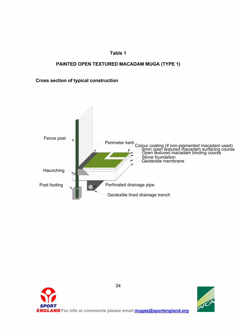
Table 1
PAINTED OPEN TEXTURED MACADAM MUGA (TYPE 1)
Cross section of typical construction
Fence postPerimeter kerb Colour coating (if non-pigmented macadam used)
6mm open textured macadam surfacing course
Stone foundationOpen textured macadam binding course
Perforated drainage pipe
Geotextile lined drainage trench
Post footing
Haunching
Geotextile membrane
For info or comments please email [email protected]
34
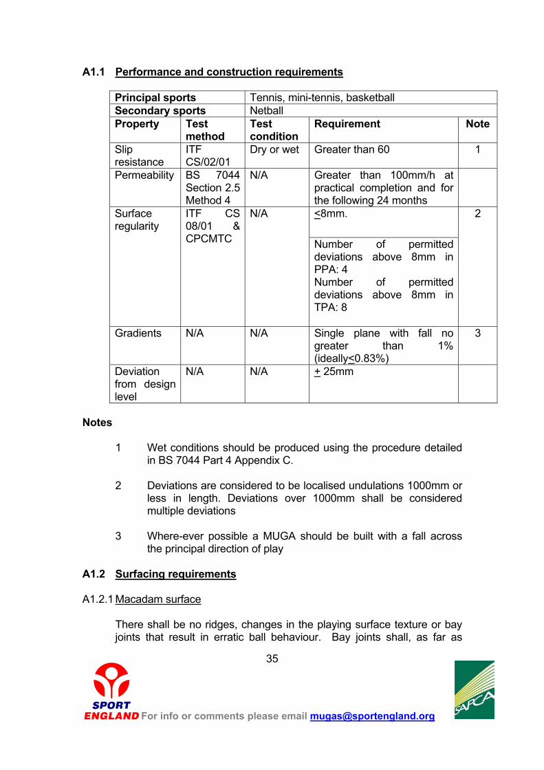
A1.1 Performance and construction requirements
Principal sports Tennis, mini-tennis, basketball Secondary sports Netball Property Test
method Test condition
Requirement Note
Slip resistance
ITF CS/02/01
Dry or wet Greater than 60 1
Permeability BS 7044 Section 2.5 Method 4
N/A Greater than 100mm/h at practical completion and for the following 24 months
<8mm. Surface regularity
ITF CS 08/01 & CPCMTC
N/A
Number of permitted deviations above 8mm in PPA: 4 Number of permitted deviations above 8mm in TPA: 8
2
Gradients N/A N/A Single plane with fall no greater than 1% (ideally<0.83%)
3
Deviation from design level
N/A N/A + 25mm
Notes
1 Wet conditions should be produced using the procedure detailed
in BS 7044 Part 4 Appendix C. 2 Deviations are considered to be localised undulations 1000mm or
less in length. Deviations over 1000mm shall be considered multiple deviations
3 Where-ever possible a MUGA should be built with a fall across
the principal direction of play A1.2 Surfacing requirements A1.2.1 Macadam surface
There shall be no ridges, changes in the playing surface texture or bay joints that result in erratic ball behaviour. Bay joints shall, as far as
For info or comments please email [email protected]
35
possible, accord with play lines and be longitudinal along the length of the court(s) with no discernible cross-joints.
A1.2.2 Colour coating
Non-pigmented macadam shall be coloured with proprietary water based polyurethane textured court paints. The Contractor’s Proposals shall include colour swatches of the paint to allow approval of the proposed colours by the Employer. A minimum of two coats of paint shall be applied in transverse directions to provide a uniform appearance. The quality of the paints shall ensure that there are no significant signs of fading, flaking or cracking for a period of three years.
A1.2.3 Line Marking
Line markings shall be in accordance with the relevant sports governing body rules. Unless stated in the rules all lines shall be 50mm wide and applied using at least two coats of paint. When measured with a calibrated steel tape all line markings shall be within 20mm of their true position as specified in the appropriate rule. Markings shall not deviate by more than 10mm from a line joining their ends, nor include any sudden steps. Line edges shall be parallel and uniform.
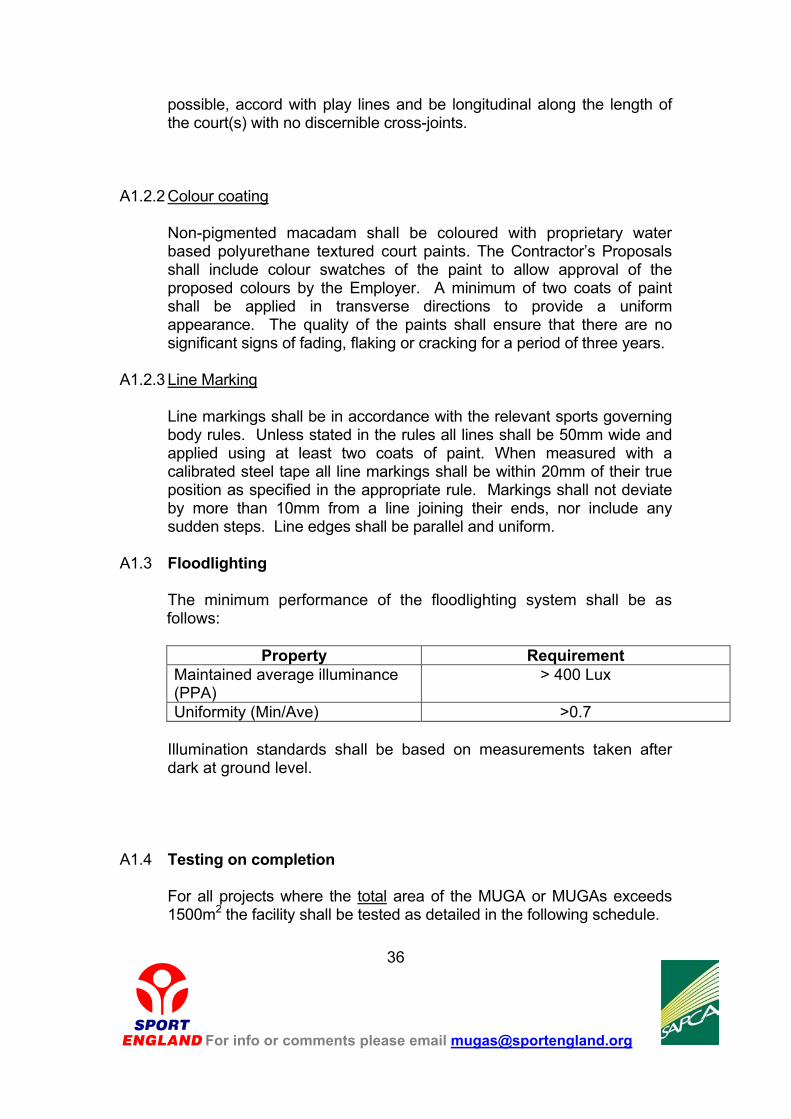
A1.3 Floodlighting
The minimum performance of the floodlighting system shall be as follows:
Property Requirement
Maintained average illuminance (PPA)
> 400 Lux
Uniformity (Min/Ave) >0.7 Illumination standards shall be based on measurements taken after
dark at ground level. A1.4 Testing on completion
For all projects where the total area of the MUGA or MUGAs exceeds 1500m2 the facility shall be tested as detailed in the following schedule.
For info or comments please email [email protected]
36
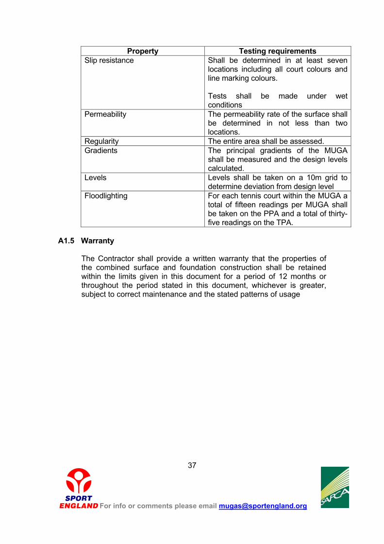
Property Testing requirements Slip resistance Shall be determined in at least seven
locations including all court colours and line marking colours. Tests shall be made under wet conditions
Permeability The permeability rate of the surface shall be determined in not less than two locations.
Regularity The entire area shall be assessed. Gradients The principal gradients of the MUGA
shall be measured and the design levels calculated.
Levels Levels shall be taken on a 10m grid to determine deviation from design level
Floodlighting For each tennis court within the MUGA a total of fifteen readings per MUGA shall be taken on the PPA and a total of thirty-five readings on the TPA.
A1.5 Warranty
The Contractor shall provide a written warranty that the properties of the combined surface and foundation construction shall be retained within the limits given in this document for a period of 12 months or throughout the period stated in this document, whichever is greater, subject to correct maintenance and the stated patterns of usage
For info or comments please email [email protected]
37
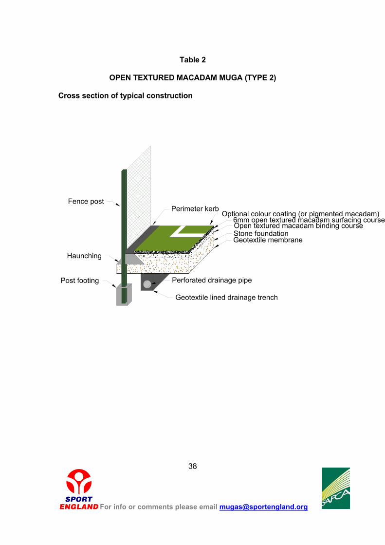
Table 2
OPEN TEXTURED MACADAM MUGA (TYPE 2)
Cross section of typical construction
Fence postPerimeter kerb
Optional colour coating (or pigmented macadam)6mm open textured macadam surfacing course
Stone foundationOpen textured macadam binding course
Perforated drainage pipe
Geotextile lined drainage trench
Post footing
Haunching
Geotextile membrane
For info or comments please email [email protected]
38

A2.1 Performance and construction requirements
Principal sports Netball (AENA Category 1 & 2 courts) Secondary sports Tennis, mini-tennis, basketball
Property Test method
Test condition
Requirement Note
Slip resistance
AENA ITF CS/02/01
Dry or wet >75 1 & 2
Traction AENA ITF CS/03/01
Dry or wet > 0.70 1 & 2
Permeability BS 7044 Section 2.5 Method 4
N/A Greater than 100mm/h at practical completion and for the following 24 months
<8mm. Surface regularity
ITF CS 08/01 & CPCMTC
N/A
Number of permitted deviations above 8mm in PPA: 4 Number of permitted deviations above 8mm in TPA: 8
3
Gradients N/A N/A Single plane with fall no greater than 1% (ideally <0.83%)
4
Deviation from design level
N/A N/A + 25mm
Notes
1 Wet conditions should be produced using the procedure detailed in BS
7044 Part 4 Appendix C.
2 Line markings and any colour coating only. 3 Deviations are considered to be localised undulations 1000mm or less in
length. Deviations over 1000mm shall be considered multiple deviations 4 Where-ever possible a MUGA should be built with a fall across the
principal direction of play
For info or comments please email [email protected]
39

A2.2 Surfacing requirements A2.2.1 Macadam surface
There shall be no ridges, changes in the playing surface texture or bay joints that result in erratic ball behaviour. Bay joints shall, as far as possible, accord with play lines and be longitudinal along the length of the court(s) with no discernible cross-joints.
A2.2.2 Colour coating
If non-pigmented macadam courts are to be colour coated the paint shall be water based polyurethane textured court paints. The Contractor’s Proposals shall include colour swatches of the paint to allow approval of the proposed colours by the Employer.
A minimum of two coats of paint shall be applied in transverse directions to provide a uniform appearance. The quality of the paints shall ensure that there are no significant signs of fading, flaking or cracking for a period of three years.
A2.2.3 Line Marking
Line markings shall be in accordance with the relevant sports governing body rules. Unless stated in the rules all lines shall be 50mm wide and applied using at least two coats of paint. When measured with a calibrated steel tape all line markings shall be within 20mm of their true position as specified in the appropriate rule. Markings shall not deviate by more than 10mm from a line joining their ends, nor include any sudden steps. Line edges shall be parallel and uniform.
A2.3 Floodlighting
The minimum performance of the floodlighting system shall be as follows:
Property Requirement
Maintained average illuminance (PPA)
>400 Lux
Uniformity (Min/Ave) >0.7
Illumination standards shall be based on measurements taken after dark at ground level.
A2.4 Testing on completion
For info or comments please email [email protected]
40

For all projects where the total area of the MUGA or MUGAs exceeds 1500m2 the facility shall be tested as detailed in the following schedule.
Property Testing requirements
Slip resistance (colour coatings and line markings)
Shall be determined in at least seven locations including all court colours and line marking colours. Tests shall be made under wet conditions
Traction (colour coating) Shall be determined in at least three locations including all court colours. Tests shall be made under wet conditions
Permeability The permeability rate of the surface shall be determined in not less than two locations.
Regularity The entire area shall be assessed. Gradients The principal gradients of the MUGA shall
be measured and the design levels calculated.
Levels Levels shall be taken on a 10m grid to determine deviation from design level
Floodlighting For each netball court a total of fifteen readings per MUGA shall be taken on the PPA .
A2.5 Warranty
The Contractor shall provide a written warranty that the properties of the combined surface and foundation construction shall be retained within the limits given in this document for a period of 12 months or throughout the period stated in this document, whichever is greater, subject to correct maintenance and the stated patterns of usage
For info or comments please email [email protected]
41
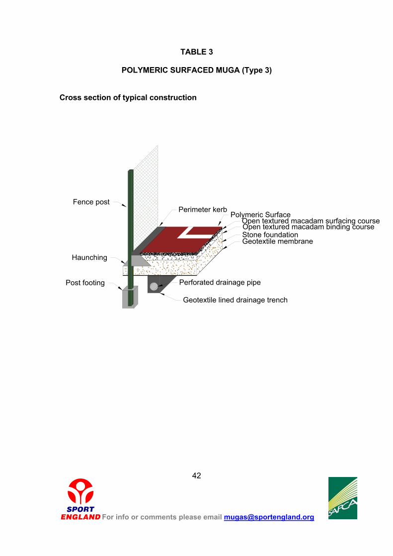
TABLE 3
POLYMERIC SURFACED MUGA (Type 3) Cross section of typical construction
Fence postPerimeter kerb
Polymeric SurfaceOpen textured macadam surfacing course
Stone foundationOpen textured macadam binding course
Perforated drainage pipe
Geotextile lined drainage trench
Post footing
Haunching
Geotextile membrane
For info or comments please email [email protected]
42
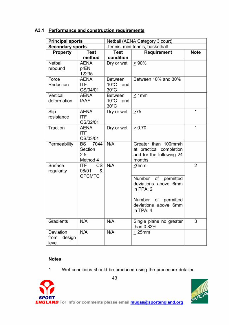
A3.1 Performance and construction requirements
Principal sports Netball (AENA Category 3 court) Secondary sports Tennis, mini-tennis, basketball
Property Test method
Test condition
Requirement Note
Netball rebound
AENA prEN 12235
Dry or wet > 90%
Force Reduction
AENA ITF CS/04/01
Between 10°C and 30°C
Between 10% and 30%
Vertical deformation
AENA IAAF
Between 10°C and 30°C
< 1mm
Slip resistance
AENA ITF CS/02/01
Dry or wet >75 1
Traction AENA ITF CS/03/01
Dry or wet > 0.70 1
Permeability BS 7044 Section 2.5 Method 4
N/A Greater than 100mm/h at practical completion and for the following 24 months
<6mm. Surface regularity
ITF CS 08/01 & CPCMTC
N/A
Number of permitted deviations above 6mm in PPA: 2 Number of permitted deviations above 6mm in TPA: 4
2
Gradients N/A N/A Single plane no greater than 0.83%
3
Deviation from design level
N/A N/A + 25mm
Notes
1 Wet conditions should be produced using the procedure detailed
For info or comments please email [email protected]
43

in BS 7044 Part 4 Appendix C. 2 Deviations are considered to be localised undulations 1000mm or
less in length. Deviations over 1000mm shall be considered multiple deviations
3 Where-ever possible a MUGA should be built with a fall across
the principal direction the direction of play
A3.2 Surfacing requirements
A3.2.1 Surfacing durability
The surfacing shall comply with the following durability requirements.
Property Test method
Test condition
Requirement
Surface durability
BS 7044 As detailed in BS 7044 Part 4
In accordance with Table 3 of BS 7044 Part 4 Class O
Surface Environmental Resistance
BS 7044 As detailed in BS 7044 Part 4
In accordance with Table 4 of BS 7044 Part 4
Tensile properties
IAAF N/A Tensile strength: 0.4 MPA Elongation at break: 40%
A3.2.2 Installation
There shall be no ridges, changes in the playing surface texture or bay joints that result in erratic ball behaviour. Bay joints shall, as far as possible, accord with play lines and be longitudinal along the length of the court(s) with no discernible cross-joints.
A3.2.3 Line Marking
Line markings shall be in accordance with the relevant sports governing body rules. Unless stated in the rules all lines shall be 50mm wide and applied using at least two coats of paint. When measured with a calibrated steel tape all line markings shall be within 20mm of their true position as specified in the appropriate rule. Markings shall not deviate by more than 10mm from a line joining their ends, nor include any sudden steps. Line edges shall be parallel and uniform.
For info or comments please email [email protected]
44
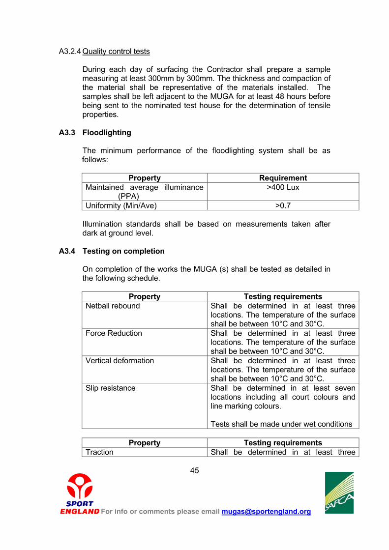
A3.2.4 Quality control tests
During each day of surfacing the Contractor shall prepare a sample measuring at least 300mm by 300mm. The thickness and compaction of the material shall be representative of the materials installed. The samples shall be left adjacent to the MUGA for at least 48 hours before being sent to the nominated test house for the determination of tensile properties.
A3.3 Floodlighting
The minimum performance of the floodlighting system shall be as follows:
Property Requirement
Maintained average illuminance (PPA)
>400 Lux
Uniformity (Min/Ave) >0.7
Illumination standards shall be based on measurements taken after dark at ground level.
A3.4 Testing on completion
On completion of the works the MUGA (s) shall be tested as detailed in the following schedule.
Property Testing requirements
Netball rebound Shall be determined in at least three locations. The temperature of the surface shall be between 10°C and 30°C.
Force Reduction Shall be determined in at least three locations. The temperature of the surface shall be between 10°C and 30°C.
Vertical deformation Shall be determined in at least three locations. The temperature of the surface shall be between 10°C and 30°C.
Slip resistance Shall be determined in at least seven locations including all court colours and line marking colours. Tests shall be made under wet conditions
Property Testing requirements
Traction Shall be determined in at least three
For info or comments please email [email protected]
45

locations including all court colours. Tests shall be made under wet conditions
Permeability The permeability rate of the surface shall be determined in not less than two locations.
Regularity The entire area shall be assessed. Gradients The principal gradients of the MUGA shall
be measured and the design levels calculated.
Levels Levels shall be taken on a 10m grid to determine deviation from design level
Floodlighting A total of fifteen readings per netball court shall be taken on the PPA.
A3.4 Warranty
The Contractor shall provide a written warranty that the properties of the combined surface and foundation construction shall be retained within the limits given in this document for a period of three years or throughout the period stated in this document, whichever is greater, subject to correct maintenance and the stated patterns of usage.
For info or comments please email [email protected]
46

TABLE 4
Polymeric surfaced MUGA (Type 4)
Cross section of typical construction
Fence post
Rebound board
Perimeter kerb Polymeric surfaceOpen textured macadam surfacing course
Stone foundationOpen textured macadam binding course
Perforated drainage pipe
Geotextile lined drainage trench
Post footing
Haunching
Geotextile membrane
For info or comments please email [email protected]
47

A4.1 Performance and construction requirements
Principal sports Five a-side, football training, athletics training Secondary sports Basketball, netball
Property Test method
Test condition
Requirement Note
Force Reduction
IAAF & UKA
Between 10°C and 30°C
Between 32% and 52%
Vertical deformation
IAAF &UKA
Between 10°C and 30°C
Between 0.6mm and 2.5mm
Slip resistance
BS 7044 Section 2.2 Method 3
Wet >55 1 & 2
Permeability BS 7044 Section 2.5 Method 4
N/A Greater than 100mm/h at practical completion and for the following twelve months
<6mm. Surface regularity
IAAF & UKA
N/A
Number of permitted deviations above 6mm in PPA: 2 Number of permitted deviations above 6mm in TPA: 4
3
Gradients N/A N/A Single plane no greater than 1%
Deviation from design level
N/A N/A + 25mm
Notes
1 Wet conditions should be produced using the procedure detailed
in BS 7044 Part 4 Appendix C. 2 Under wet and damp conditions this value of slip resistance may
be considered slippery by tennis and netball players 3 Deviations are considered to be localised undulations 1000mm or
less in length. Deviations over 1000mm shall be considered multiple deviations
For info or comments please email [email protected]
48

A4.2 Surfacing requirements
A4.2.1 Surfacing durability
The surfacing shall comply with the following durability requirements.
Property Test method
Test condition
Requirement
Surface durability
BS 7044 As detailed in BS 7044 Part 4
In accordance with Table 3 of BS 7044 Part 4 Class SR/O if spikes are to be used or Class O if not
Surface Environmental Resistance
BS 7044 As detailed in BS 7044 Part 4
In accordance with Table 4 of BS 7044 Part 4
Tensile properties
IAAF N/A Tensile strength: 0.4 MPA Elongation at break: 40%
A4.2.2 Installation
There shall be no ridges, changes in the playing surface texture or bay joints that result in erratic ball behaviour. Bay joints shall, as far as possible, accord with play lines and be longitudinal along the length of the court(s) with no discernible cross-joints.
A4.2.3 Line Marking
Line markings shall be in accordance with the relevant sports governing body rules. Unless stated in the rules all lines shall be 50mm wide and applied using at least two coats of paint. When measured with a calibrated steel tape all line markings shall be within 20mm of their true position as specified in the appropriate rule. Markings shall not deviate by more than 10mm from a line joining their ends, nor include any sudden steps. Line edges shall be parallel and uniform.
A4.2.4 Quality control tests
During each day of surfacing the contractor shall prepare a sample measuring at least 300mm by 300mm. The thickness and compaction of the material shall be representative of the materials installed. The samples shall be left adjacent to the MUGA for at least 48 hours before being sent to the nominated test house for the determination of tensile properties.
For info or comments please email [email protected]
49

A4.3 Floodlighting
The minimum performance of the floodlighting system shall be as follows:
Property Requirement
Maintained average illuminance - Full lighting
>200 Lux
Uniformity (Min/Ave) – Full Lighting
> 0.7
Maintained average illuminance – secondary level lighting for training etc
> 200 Lux
Illumination standards shall be based on measurements taken after dark at ground level.
A4.4 Testing on completion
On completion of the works the MUGA (s) shall be tested as detailed in the following schedule.
Property Testing requirements
Force Reduction Shall be determined in at least three locations. The temperature of the surface shall be between 10°C and 30°C.
Vertical deformation Shall be determined in at least three locations. The temperature of the surface shall be between 10°C and 30°C.
Slip resistance Shall be determined in at least five locations including all court colours and line marking colours. Tests shall be made under wet conditions
Permeability The permeability rate of the surface shall be determined in not less than two locations.
Regularity The entire area shall be assessed.
Property Testing requirements Gradients The principal gradients of the MUGA
shall be measured and the design levels calculated.
For info or comments please email [email protected]
50

Levels Levels shall be taken on a 10m grid to determine deviation from design level
Floodlighting Measurements shall be made on a 10m grid offset from the centre spot of the MUGA.
A4.5 Warranty
The Contractor shall provide a written warranty that the properties of the combined surface and foundation construction shall be retained within the limits given in this document for a period of three years or throughout the period stated in this document, whichever is greater, subject to correct maintenance and the stated patterns of usage
For info or comments please email [email protected]
51

TABLE 5
Sand filled/dressed synthetic turf surfaced MUGA (Type 5) or STP
Cross section of typical construction
Fence post
Rebound board or kick board
Perimeter kerb Synthetic turfShockpadOpen textured macadam binding courseOpen textured macadam surfacing course
Perforated drainage pipe
Geotextile lined drainage trench
Post footing
Haunching
Geotextile membraneStone foundation
For info or comments please email [email protected]
52

A5.1 Performance and construction requirements
Principal sports Hockey, football and five-a-side football Secondary sports Lacrosse, rugby training (not scrumagging), and
athletics training Property Test
method Test
condition Requirement
Hockey ball rebound
FIH Wet between 10°C and 30°C
Between 120mm and 300mm
Football rebound
BS 7044 Section 2.1 Method 1
Dry and wet between 10°C and 30°C
Between 25% and 50%
Hockey ball roll
BS 7044 Section 2.1 Method 2
Wet Between 5m and 15m. Maximum deviation from straight line of 3°
Football velocity change
BS 7044 Section 2.1 Method 3
Dry and wet
Between 0.25m/s and 0.75m/s
Force Reduction
FIH Wet between 10°C and 30°C
Between 40% and 65%
Peak deceleration
BS 7044 Section 2.2 Method 4
Dry and wet between 10°C and 30°C
Peak deceleration of 200g at fall height of 1m or greater
Surface friction
FIH Wet Between 0.60 and 1.20
Rotational friction (traction)
BS 7044 Section 2.2
Dry or wet Between 1.1 and 2.0
Permeability BS 7044 Section 2.5 Method 4
N/A Greater than 100mm/h
For info or comments please email [email protected]
53

Property Test
method Test
condition Requirement
Surface regularity
3m straight-edge
N/A <6mm.
Gradients N/A N/A No greater than 1% in any direction Deviation from design level
N/A N/A + 25mm
A5.2 Surfacing requirements A5.2.1 Shockpad Installation
In-situ shockpads shall be laid to the contractor’s specified depth. No joint should vary in level by more than 2mm. The regularity of the installed shockpad shall be in accordance with the requirement for the playing surface. The design of the shockpad and carpet backing shall ensure that slippage of the synthetic turf carpet does not occur. Prefabricated rubber and fibre shockpads shall be adequately dimensionally stable to ensure that rucking, creasing or movement does not occur. They shall either be ribbon bonded to the macadam base or seamed along all side and head joints.
A5.2.2 Carpet Installation
The synthetic turf shall be laid with continuous seams for the full width or length. No head joints shall be permitted within the actual playing area without the prior agreement of the Employer. No seam shall be closer than 300mm to any parallel inlaid line. The edge seams shall be straight to within +25mm of a line joining their ends. The method of jointing and seaming, including all in-laid line markings, shall be such that no ridge, groove, crease, or change in surface texture shall be apparent along any joint or seam to the extent that it may cause or result in the deviation from a straight line of a hockey ball rolling across the joint or seam at an angle of 10° and at a speed of 1 metre/sec + 10%. Notwithstanding this requirement, there shall be no height difference or separation at the joints of greater than 2mm.
For info or comments please email [email protected]
54
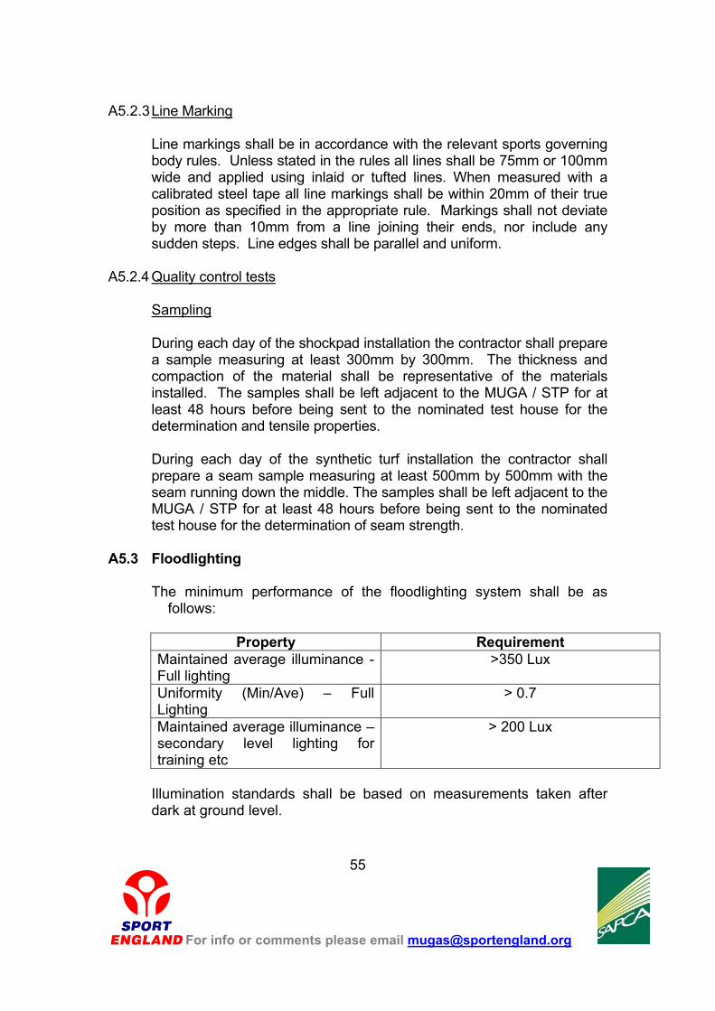
A5.2.3 Line Marking
Line markings shall be in accordance with the relevant sports governing body rules. Unless stated in the rules all lines shall be 75mm or 100mm wide and applied using inlaid or tufted lines. When measured with a calibrated steel tape all line markings shall be within 20mm of their true position as specified in the appropriate rule. Markings shall not deviate by more than 10mm from a line joining their ends, nor include any sudden steps. Line edges shall be parallel and uniform.
A5.2.4 Quality control tests
Sampling
During each day of the shockpad installation the contractor shall prepare a sample measuring at least 300mm by 300mm. The thickness and compaction of the material shall be representative of the materials installed. The samples shall be left adjacent to the MUGA / STP for at least 48 hours before being sent to the nominated test house for the determination and tensile properties. During each day of the synthetic turf installation the contractor shall prepare a seam sample measuring at least 500mm by 500mm with the seam running down the middle. The samples shall be left adjacent to the MUGA / STP for at least 48 hours before being sent to the nominated test house for the determination of seam strength.
A5.3 Floodlighting
The minimum performance of the floodlighting system shall be as
follows:
Property Requirement Maintained average illuminance - Full lighting
>350 Lux
Uniformity (Min/Ave) – Full Lighting
> 0.7
Maintained average illuminance – secondary level lighting for training etc
> 200 Lux
Illumination standards shall be based on measurements taken after dark at ground level.
For info or comments please email [email protected]
55
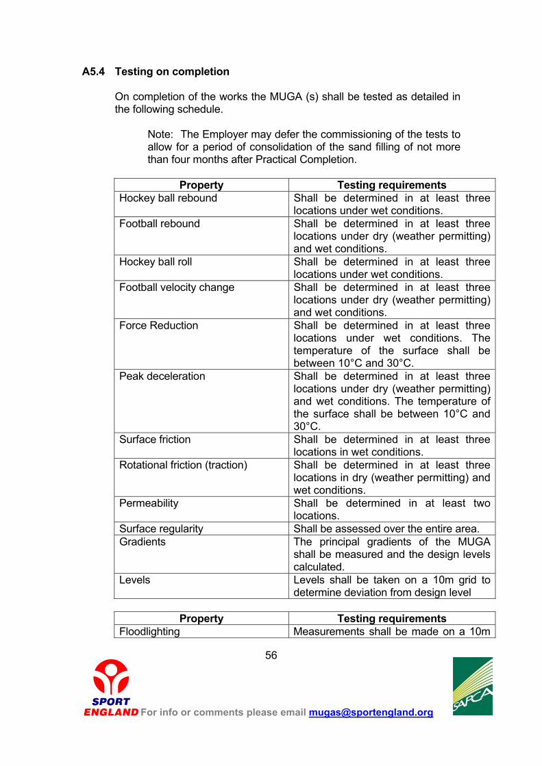
A5.4 Testing on completion On completion of the works the MUGA (s) shall be tested as detailed in the following schedule.
Note: The Employer may defer the commissioning of the tests to allow for a period of consolidation of the sand filling of not more than four months after Practical Completion.
Property Testing requirements
Hockey ball rebound Shall be determined in at least three locations under wet conditions.
Football rebound Shall be determined in at least three locations under dry (weather permitting) and wet conditions.
Hockey ball roll Shall be determined in at least three locations under wet conditions.
Football velocity change Shall be determined in at least three locations under dry (weather permitting) and wet conditions.
Force Reduction Shall be determined in at least three locations under wet conditions. The temperature of the surface shall be between 10°C and 30°C.
Peak deceleration Shall be determined in at least three locations under dry (weather permitting) and wet conditions. The temperature of the surface shall be between 10°C and 30°C.
Surface friction Shall be determined in at least three locations in wet conditions.
Rotational friction (traction) Shall be determined in at least three locations in dry (weather permitting) and wet conditions.
Permeability Shall be determined in at least two locations.
Surface regularity Shall be assessed over the entire area. Gradients The principal gradients of the MUGA
shall be measured and the design levels calculated.
Levels Levels shall be taken on a 10m grid to determine deviation from design level
Property Testing requirements
Floodlighting Measurements shall be made on a 10m
For info or comments please email [email protected]
56

grid offset from the centre spot of the MUGA.
A5.5 Warranty
The Contractor shall provide a written warranty that the properties of the combined surface and foundation construction shall be retained within the limits given in this document for a period of five years or throughout the period stated in this document, whichever is greater, subject to correct maintenance and the stated patterns of usage.
For info or comments please email [email protected]
57

APPENDIX B
SITE AND PROJECT SPECIFIC REQUIREMENTS
In order to allow meaningful tenders the developer should detail all the site and project specific information relating to the scheme in the Employer’s Requirements. This will include:
1. A summary of the proposed sports to be played on the MUGA / STP
2. A prediction of the likely weekly usage
3. The type of MUGA / STP required (as detailed in Appendix A)
4. The layout and dimensions (normally shown on a layout drawing)
5. The type and location of all temporary fencing required to secure the site during construction
6. Site or project specific restrictions and requirements (planning,
drainage outfall, services, etc.)
7. Details of all enabling works to be undertaken by others in advance of the works
8. The outlet for the drainage system
9. The form of surfacing required
10. The colour (s) of the surfacing
11. The line markings required and their colours
12. The type of fencing required (height, gates gate height and width,
rebound boards – type and colour, kick boards – type and colour, mesh type, mesh finish, etc.)
13. The type of floodlighting required (light source, luminaire type,
column height and number, column colour, etc)
14. The location of the control and switchgear for the floodlighting system
15. The available power supply for the floodlighting system or details of who is to provide an adequate supply
16. Details of any secondary level floodlighting to be provided for training
and other activities
17. Details of all small power, egress and amenity lighting and all control features to be provided as part of the floodlighting.
18. The sports equipment and fixtures to be supplied as part of the
For info or comments please email [email protected]
58

contract and whether they are to be free standing or socketed.
19. A schedule of sampling required of the contractor during construction of the MUGA.
20. Details of all external maintenance access ways and footpaths etc to
be constructed by the contractor / STP.
21. The form of contract to be used, together with all preliminaries, preambles, conditions and amendments.
22. Any conditions of tendering or procurement stipulated by funding
partners
For info or comments please email [email protected]
59
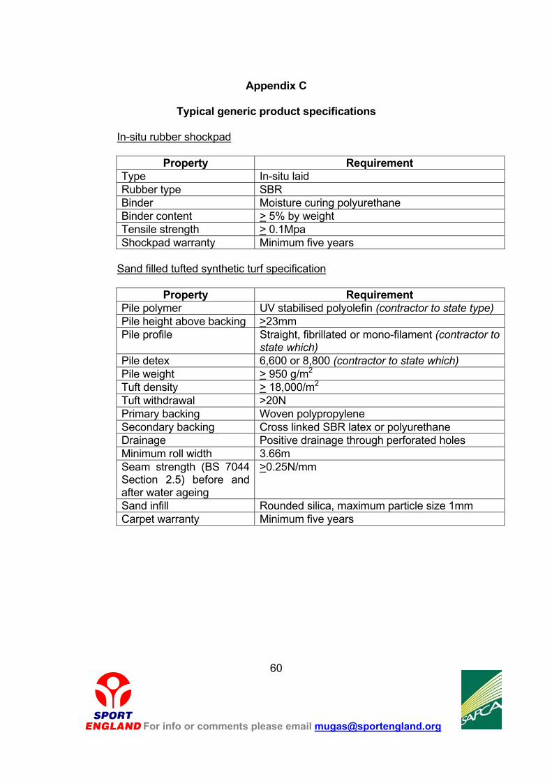
Appendix C
Typical generic product specifications
In-situ rubber shockpad
Property Requirement Type In-situ laid Rubber type SBR Binder Moisture curing polyurethane Binder content > 5% by weight Tensile strength > 0.1Mpa Shockpad warranty Minimum five years
Sand filled tufted synthetic turf specification
Property Requirement
Pile polymer UV stabilised polyolefin (contractor to state type) Pile height above backing >23mm Pile profile Straight, fibrillated or mono-filament (contractor to
state which) Pile detex 6,600 or 8,800 (contractor to state which) Pile weight > 950 g/m2 Tuft density > 18,000/m2 Tuft withdrawal >20N Primary backing Woven polypropylene Secondary backing Cross linked SBR latex or polyurethane Drainage Positive drainage through perforated holes Minimum roll width 3.66m Seam strength (BS 7044 Section 2.5) before and after water ageing
>0.25N/mm
Sand infill Rounded silica, maximum particle size 1mm Carpet warranty Minimum five years
For info or comments please email [email protected]
60

Sand dressed tufted synthetic turf
Property Requirement
Pile polymer UV stabilised polyolefin (contractor to state type) Pile height above backing >12mm Pile profile Fibrillated or mono-filament (contractor to state
which) Pile detex 6,600 or 8,800 (contractor to state which) Pile weight > 1,400 g/m2 Tuft density > 35,000/m2 Tuft withdrawal >20N Primary backing Woven polypropylene Secondary backing Cross linked SBR latex or polyurethane Drainage Positive drainage through perforated holes Minimum roll width 3.66m Seam strength (BS 7044 Section 2.5) before and after water ageing
>0.25N/mm
Sand infill Rounded silica, maximum particle size 1mm Carpet warranty Minimum five years
Needle-punched sand-filled/sand-dressed synthetic turf
Property Requirement Manufacturing method Needle-punched/fibre bonded Fibre type UV stabilised polypropylene Pile height above backing
> 11mm
Pile profile Random orientation, vertical loop or straight pile
Fibre weight > 1150 g/m2 Resin binder Cross linking SBR compound Total weight > 1300 g/m2 Backing thickness ≥ 3mm Drainage Positive drainage through entire structure Seam strength (BS7044 Section 2.5) before and after ageing
> 0.25 n/mm
Sand infill Rounded silica, maximum particle size 1mmCarpet warranty Minimum 5 years
For info or comments please email [email protected]
61

Acknowledgements The following organisations prepared this guidance: Sport England 16 Upper Woburn Place London WC1H 0QP Tel: 020 7273 1500 Fax: 020 7387 1999 Web: www.sportengland.org The Sports and Play Construction Association Federation House National Agricultural Centre Stoneleigh Park Warwickshire CV8 2RF
Tel: 024 7641 6316 Fax: 024 7641 4773 E-mail: [email protected] Web: www.sapca.org.uk Materials Science Consultants Ltd Unit 11 Lime Tree Business Park Lime Tree Road Matlock Derbyshire DE4 3EJ Tel: 01629 58 33 66 Fax: 01629 58 33 77 E-mail: [email protected] Michael Abbott Associates 13 Willow Tree Place Balerno Midlothian Scotland EH14 5AZ Tel: 0131 449 2287 Fax: 0131 451 5623 E-mail: [email protected]
For info or comments please email [email protected]
62