A Guide to Simple IP Camera Deployment Using ZyXEL ... Guide to Simple IP Camera Deployment Using...
15
A Guide to Simple IP Camera Deployment Using ZyXEL Bandwidth Solutions
Transcript of A Guide to Simple IP Camera Deployment Using ZyXEL ... Guide to Simple IP Camera Deployment Using...
A Guide to Simple IP Camera
Deployment Using ZyXEL
Bandwidth Solutions

2015/7/22
ZyXEL Communications Corporation
Barney Gregorio
Overview:
This article contains guidelines on how to introduce IP cameras into your local network using
ZyXEL switches. This article focuses on how to optimize and fine-tune the networks bandwidth
requirement. This article assumes that IP camera service is deployed for small to medium
businesses and uses unicast instead of multicast. Interaction between the IP camera and server
will be strictly through the same layer-2 domain and will not cross any gateways.
Objectives:
- Present configuration examples using Web GUI
- Present scenario on bandwidth optimization
- Troubleshooting VLAN and PoE
Bandwidth Optimization:
This section will now consider the bandwidth of your surveillance traffic. Every link has a
maximum transmission rate. 1000Base-T for instance, has a maximum allowable transmission
rate of 1Gbps. Each IP camera needs to transmit its video to the server. This can easily create a
bottleneck within some of your links. This is especially true on the link leading to your IP camera
server. If you fail to properly configure your bandwidth, your surveillance network may suffer
from poor video quality or momentary loss of service.
There are four variables to consider in calculating each individual IP camera’s bandwidth
consumption. Compression Type, Resolution, Video Quality, and Frame Rate.
We have provided a table for your bandwidth consumption reference. Note that the Video Quality
will be fixed in medium quality. The output bandwidth of each camera will be in megabits per
second (Mbps).
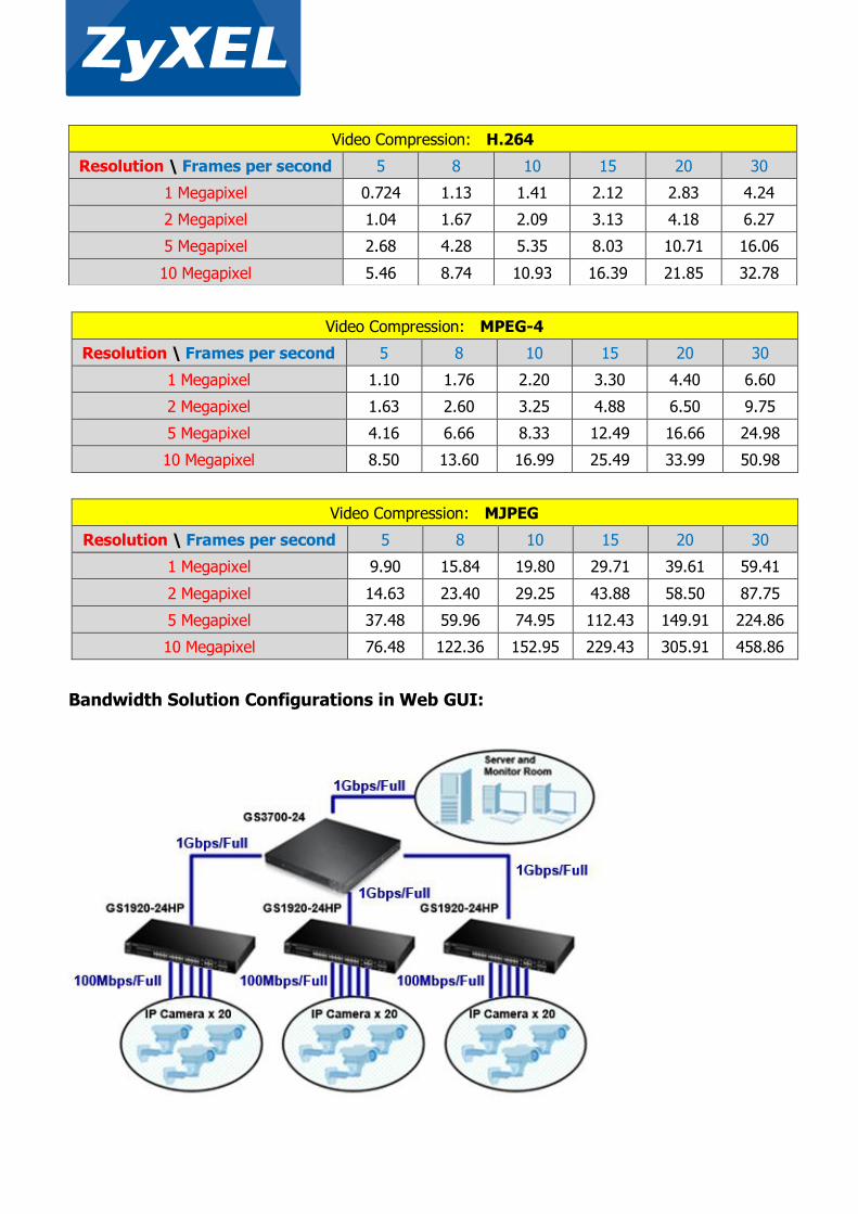
Video Compression: MPEG-4
Resolution \ Frames per second 5 8 10 15 20 30
1 Megapixel 1.10 1.76 2.20 3.30 4.40 6.60
2 Megapixel 1.63 2.60 3.25 4.88 6.50 9.75
5 Megapixel 4.16 6.66 8.33 12.49 16.66 24.98
10 Megapixel 8.50 13.60 16.99 25.49 33.99 50.98
Video Compression: MJPEG
Resolution \ Frames per second 5 8 10 15 20 30
1 Megapixel 9.90 15.84 19.80 29.71 39.61 59.41
2 Megapixel 14.63 23.40 29.25 43.88 58.50 87.75
5 Megapixel 37.48 59.96 74.95 112.43 149.91 224.86
10 Megapixel 76.48 122.36 152.95 229.43 305.91 458.86
Bandwidth Solution Configurations in Web GUI:
Video Compression: H.264
Resolution \ Frames per second 5 8 10 15 20 30
1 Megapixel 0.724 1.13 1.41 2.12 2.83 4.24
2 Megapixel 1.04 1.67 2.09 3.13 4.18 6.27
5 Megapixel 2.68 4.28 5.35 8.03 10.71 16.06
10 Megapixel 5.46 8.74 10.93 16.39 21.85 32.78

Devices:
Quantity Device
1 GS3700-24
3 GS1920-24HP
60 IP Camera
Objectives:
- Under no circumstances will there be any packet loss between IP cameras and IP camera
server.
- For low quality video setting, the physical network topology must not be changed
- Other network services should still function albeit with acceptable packet loss
- IP camera traffic will use priority queue 6
Two scenarios will be implemented. The first scenario will assume that the IP cameras are all
configured to produce the same lower quality video and bandwidth requirement. The second
scenario will assume that the IP cameras are all configured to produce the same higher quality
video and bandwidth requirement. We will assume that the VLAN configurations have already
been implemented. Links between the access switch to the IP cameras uses 100Mbps as most
PD only supports this transmission speed. We will also assume that this network is not just
running a surveillance network but other services as well. The server also has multiple network
interfaces allowing link aggregation or LACP as a valid solution.
For the fourth objective, we need to ensure that packets from the IP camera uses priority queue
6. You can do this by going to Basic Setting -> Port Setup and set all ports directly
connected to your IP cameras with 802.1p Priority: 6

Scenario 1 (Low Quality):
For this scenario, each IP cameras have been configured with the following video format:
Compression: H.264
Resolution: 5 megapixel
Quality: Medium
Frames per second: 8 fps
Using the table above, we can determine that the bandwidth consumption of each individual IP
camera is approximately 4.28 Mbps.
With 20 IP cameras and each transmitting at 4.28 Mbps, the link between access layers to
aggregation layer must have a reserved bandwidth of at least 85.6 Mbps to ensure continued
video service during congestion. The link between the core switch and server, on the other hand
must reserve 256.8 Mbps.
In order to meet the first and second objectives, we will need to optimize bandwidth using
Queueing Method. Weighted Fair Queuing (WFQ) is the queueing method option that allows the
switch to reserve bandwidth per queue based on weights during congestion. The reserved
bandwidth for each queue can be calculated using this formula:
Reserved Bandwidth = Weight of Queue * Port Speed / Total Weight
We know that the bandwidth between the core switch and server must be at least 256.8 Mbps.
So let us calculate if the default configuration will reserve Queue 6 with enough bandwidth.
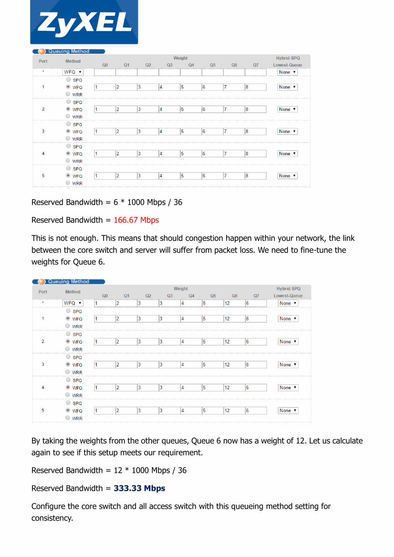
Reserved Bandwidth = 6 * 1000 Mbps / 36
Reserved Bandwidth = 166.67 Mbps
This is not enough. This means that should congestion happen within your network, the link
between the core switch and server will suffer from packet loss. We need to fine-tune the
weights for Queue 6.
By taking the weights from the other queues, Queue 6 now has a weight of 12. Let us calculate
again to see if this setup meets our requirement.
Reserved Bandwidth = 12 * 1000 Mbps / 36
Reserved Bandwidth = 333.33 Mbps
Configure the core switch and all access switch with this queueing method setting for
consistency.

Scenario 2 (High quality):
This time, we will see what happens when we raise the frames per second of the IP camera to
30 fps. It is expected that the overall bandwidth will increase significantly.
IP Camera Setup
Compression: H.264
Resolution: 5 megapixel
Quality: Medium
Frames per second: 30 fps
Bandwidth of each IP camera: 16.06 Mbps
The link between access switches and core switch now uses 321.2 Mbps. The link between core
switch and server has now risen to 963.6 Mbps. This has now become a problem that queueing
method cannot easily solve. 963.3 Mbps is more than 90% of the allowable transmission rate of
this link. In this case, we should now use Link Aggregation on the link between core switch and
server.
Link Aggregation is the grouping of physical ports into one logical higher-capacity link. This
allows your surveillance traffic to be distributed among the aggregated links. Remember, when
configuring Link Aggregation, it is important to complete your configurations before physically
attaching the extra cables. Failure to configure Link Aggregation before attaching the extra
cable will result in a loop.

Go to Advance Application -> Link Aggregation -> Link Aggregation Setting of the
core switch.
We will use T1 as the trunk interface. Check the Active box for T1. Leave criteria as
src-dst-mac.
Below, set the ports you will use to link aggregate as T1. In this case, the core switch is
currently physically connected to port 20. A second and third cable will be attached on port 21
and 22 afterwards.
In case your server only support LACP, go to Advance Application -> Link Aggregation ->
Link Aggregation Setting -> LACP.
Check the Active box and the T1 LACP Active box.
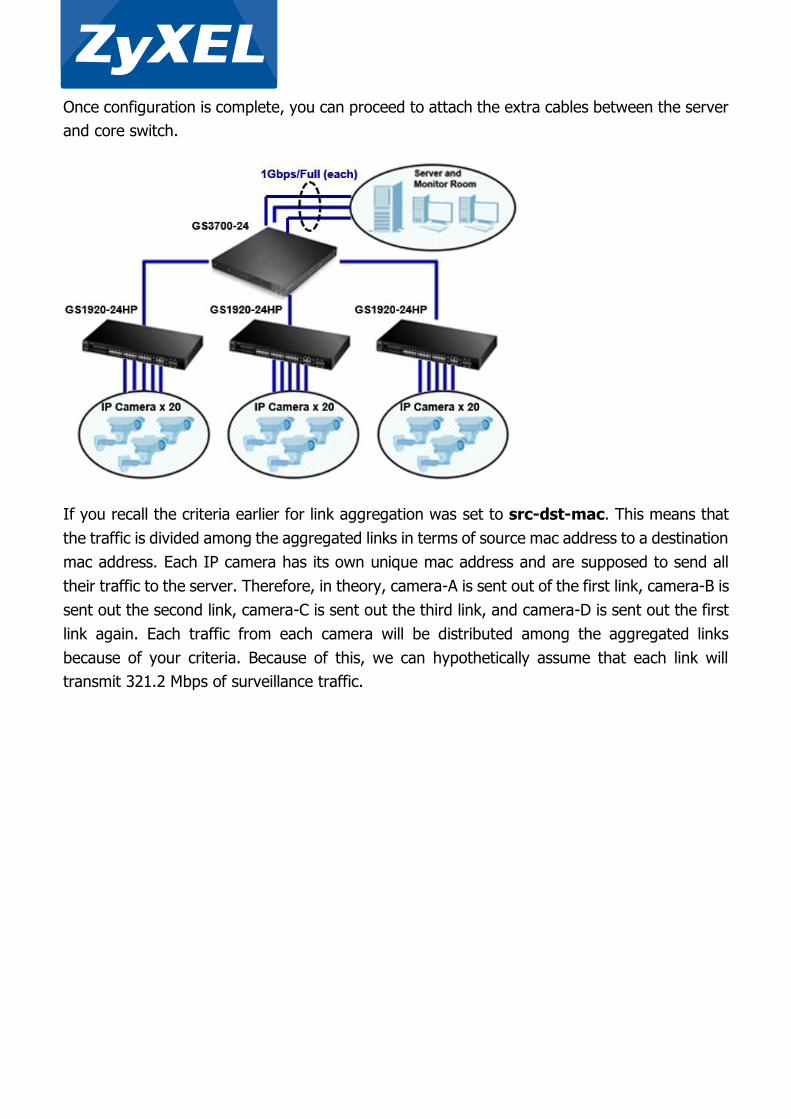
Once configuration is complete, you can proceed to attach the extra cables between the server
and core switch.
If you recall the criteria earlier for link aggregation was set to src-dst-mac. This means that
the traffic is divided among the aggregated links in terms of source mac address to a destination
mac address. Each IP camera has its own unique mac address and are supposed to send all
their traffic to the server. Therefore, in theory, camera-A is sent out of the first link, camera-B is
sent out the second link, camera-C is sent out the third link, and camera-D is sent out the first
link again. Each traffic from each camera will be distributed among the aggregated links
because of your criteria. Because of this, we can hypothetically assume that each link will
transmit 321.2 Mbps of surveillance traffic.

Together with the previous Queuing Method settings, we have already ensured 333.33 Mbps of
bandwidth for each link. The network has now been properly configured to optimize the
bandwidth of your surveillance traffic.
Troubleshooting VLAN:
1. From the port connected to the IP camera, ping the IP camera server’s IP address. A
successful ping shows that traffic is flowing both ways. If ping is unsuccessful, verify that
packets are processed in the correct VLAN.
a. Go to Management -> MAC Table.
b. Select condition: All.
c. Click the “Search” button.
d. A list should appear similar to the image above.
e. Look for the MAC address of the IP camera. If MAC address does not appear, then IP
camera most likely has not sent any packets to the switch within the past five

minutes. If MAC address of the IP camera does appear in the MAC table but in an
incorrect VLAN, then there is a strong indication of misconfiguration.
2. The ZyXEL VLAN concept follows three rules: the ingress, forwarding, and egress rule. This
refers to the PVID, normal/fix/forbidden ports, and Tx-tagging; respectively. Make sure all
three rules meet your network policy.
3. If the MAC address of the IP camera does appear in MAC table of your uplink switches and
are processed in the correct VLAN, the final thing to consider is if the packets sent to either
the IP cameras or server carries any VLAN tag. End-devices by default cannot process
packets with VLAN tags. Make sure that ports leading to your IP cameras or servers are set
to “untagged”.
Troubleshooting PoE:
1. Verify the Ethernet cable condition.
a. Make sure that the Ethernet cable length does not exceed 100 meters.
b. If PD does not power-on, try swapping the Ethernet cable with a cable that has proven
to have no issues powering-on different PD.
c. To further determine the condition of the Ethernet cable, go to Management ->
Diagnostic of the web GUI.
d. Select “Cable Diagnostics” and input the port the end-device is connected to.
e. Pairs A, B, C, and D should have an “Ok” pair status. If not, please change the cable.
2. Try creating a table to list down which ports were able to power-on PD during your test:
Device PD Model X (1) PD Model X (2) PD Model Y
Switch Model X (1)
Switch Model X (2)
Switch Model Y
Testing must be done in an isolated environment. Meaning Switch will only be connected to
one PD at a time during testing and no other. Consumption mode is the recommended PoE
mode when doing this test.
Switch Model X (1) refers to the reported switch with issue.
Switch Model X (2) refers to a different switch but the same model as the reported switch.
Switch Model Y refers to a different switch but of a different model. Preferably a newer
series.

PD Model X (1) refers to the reported PD that has issue.
PD Model X (2) refers to a different PD but same model as the reported PD.
PD Model Y refers to a different PD but of a different model.
Various kinds of conclusions can be made by inspecting the results. Some examples are:
a. Indicates that PD Model X (1) has hardware issue.
Device PD Model X (1) PD Model X (2) PD Model Y
Switch Model X (1) None All All
Switch Model X (2) None All All
Switch Model Y None All All
No ports among all switch could power-on PD Model X (1), while PD Model X (2) shows
a different result.
b. Indicates that your switch has hardware issue.
Device PD Model X (1) PD Model X (2) PD Model Y
Switch Model X (1) None None None
Switch Model X (2) All All All
Switch Model Y All All All
Switch Model X (1) could not power-on any PD among any of its ports.
or
Device PD Model X (1) PD Model X (2) PD Model Y
Switch Model X (1) 1-8 1-8 1-8
Switch Model X (2) All All All
Switch Model Y All All All
Switch Model X (1) could only power-on PD among some of its ports.
c. Indicates an interoperability issue.
Device PD Model X (1) PD Model X (2) PD Model Y
Switch Model X (1) None None All
Switch Model X (2) None None All
Switch Model Y All All All
Switch of the same model could not power-on PD of the same model among any of its
ports.
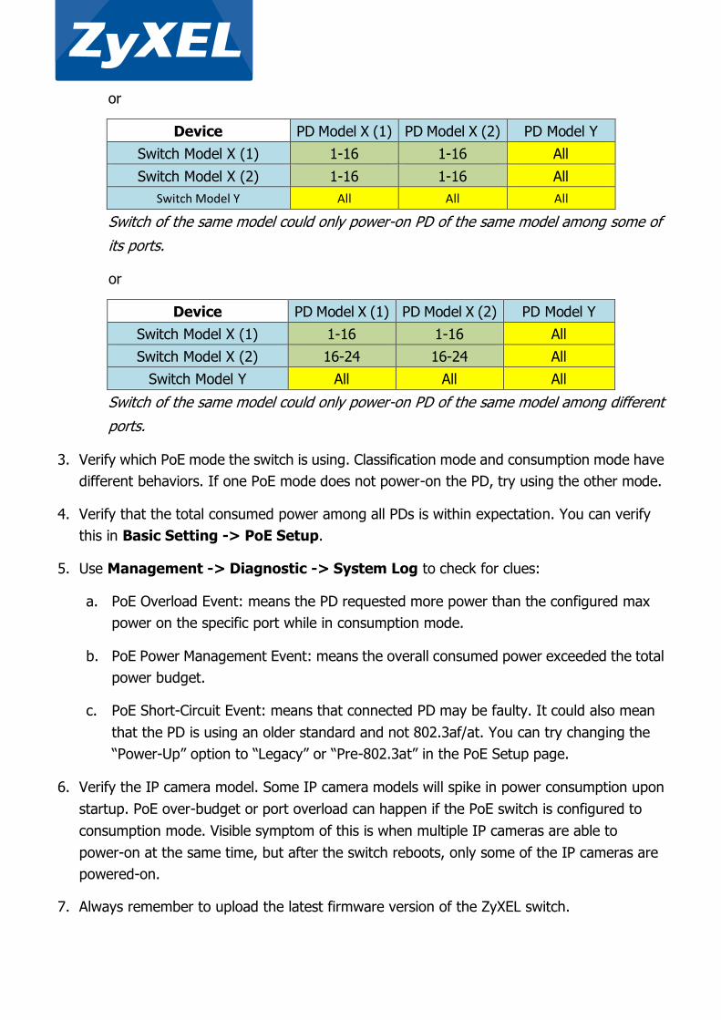
or
Device PD Model X (1) PD Model X (2) PD Model Y
Switch Model X (1) 1-16 1-16 All
Switch Model X (2) 1-16 1-16 All
Switch Model Y All All All
Switch of the same model could only power-on PD of the same model among some of
its ports.
or
Device PD Model X (1) PD Model X (2) PD Model Y
Switch Model X (1) 1-16 1-16 All
Switch Model X (2) 16-24 16-24 All
Switch Model Y All All All
Switch of the same model could only power-on PD of the same model among different
ports.
3. Verify which PoE mode the switch is using. Classification mode and consumption mode have
different behaviors. If one PoE mode does not power-on the PD, try using the other mode.
4. Verify that the total consumed power among all PDs is within expectation. You can verify
this in Basic Setting -> PoE Setup.
5. Use Management -> Diagnostic -> System Log to check for clues:
a. PoE Overload Event: means the PD requested more power than the configured max
power on the specific port while in consumption mode.
b. PoE Power Management Event: means the overall consumed power exceeded the total
power budget.
c. PoE Short-Circuit Event: means that connected PD may be faulty. It could also mean
that the PD is using an older standard and not 802.3af/at. You can try changing the
“Power-Up” option to “Legacy” or “Pre-802.3at” in the PoE Setup page.
6. Verify the IP camera model. Some IP camera models will spike in power consumption upon
startup. PoE over-budget or port overload can happen if the PoE switch is configured to
consumption mode. Visible symptom of this is when multiple IP cameras are able to
power-on at the same time, but after the switch reboots, only some of the IP cameras are
powered-on.
7. Always remember to upload the latest firmware version of the ZyXEL switch.

8. If you are still having trouble resolving the issue or that you are unsure with your
conclusions, kindly contact your local support and provide the following:
a. Specific model of the IP camera
b. Datasheet of the IP camera models with trouble powering-on
c. Firmware of the ZyXEL switch models
d. Running configuration of your ZyXEL switches
e. Network topology
f. Screenshot of the PoE Status page when issue has occurred
g. The complete System Log display in web GUI or “show logging” in CLI
F o r m o r e p r o d u c t i n f o r m a t i o n , v i s i t u s o n t h e w e b a t w w w . Z y X E L . c o m Copyright © 2015 ZyXEL Communications Corp. All rights reserved. ZyXEL, ZyXEL logo are registered trademarks of ZyXEL Communications Corp. All other brands,
product names, or trademarks mentioned are the property of their respective owners. All specifications are subject to change without notice.