Design and Adaptation of a Commercial Cold Storage Room for ...
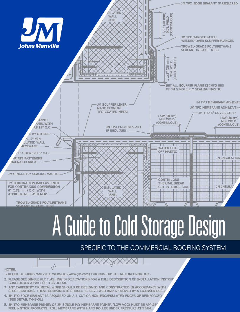
A Guide to Cold Storage DesignSPECIFIC TO THE COMMERCIAL ROOFING SYSTEM
Table of Contents
Introduction . . . . . . . . . . . . . . . . . . . . . . . . . . . . . . . . . . . . . . . . . . . . . . . . . . . . . . . . . . . . . . . . . . . . . . . . . . . . . . . . . . . . . . . . . . . . . . . . . . . . . . . 2 About Johns Manville . . . . . . . . . . . . . . . . . . . . . . . . . . . . . . . . . . . . . . . . . . . . . . . . . . . . . . . . . . . . . . . . . . . . . . . . . . . . . . . . . . . . . . . . . . . . . . . . . . . . . . . 2Considerations . . . . . . . . . . . . . . . . . . . . . . . . . . . . . . . . . . . . . . . . . . . . . . . . . . . . . . . . . . . . . . . . . . . . . . . . . . . . . . . . . . . . . . . . . . . . . . . . . . . . 2Guarantee Program . . . . . . . . . . . . . . . . . . . . . . . . . . . . . . . . . . . . . . . . . . . . . . . . . . . . . . . . . . . . . . . . . . . . . . . . . . . . . . . . . . . . . . . . . . . . . . . . . . . . . . . . . . 2About Cold Storage Buildings . . . . . . . . . . . . . . . . . . . . . . . . . . . . . . . . . . . . . . . . . . . . . . . . . . . . . . . . . . . . . . . . . . . . . . . . . . . . . . . . . . . . . . . . . . . . . . . . 3Basics of Moisture Control . . . . . . . . . . . . . . . . . . . . . . . . . . . . . . . . . . . . . . . . . . . . . . . . . . . . . . . . . . . . . . . . . . . . . . . . . . . . . . . . . . . . . . . . . . . . . . . . . . . 3 Vapor Drive . . . . . . . . . . . . . . . . . . . . . . . . . . . . . . . . . . . . . . . . . . . . . . . . . . . . . . . . . . . . . . . . . . . . . . . . . . . . . . . . . . . . . . . . . . . . . . . . . . . . . . . . . . . . . . . . 3 Condensation Control . . . . . . . . . . . . . . . . . . . . . . . . . . . . . . . . . . . . . . . . . . . . . . . . . . . . . . . . . . . . . . . . . . . . . . . . . . . . . . . . . . . . . . . . . . . . . . . . . . . . . . . 3 Air Leakage . . . . . . . . . . . . . . . . . . . . . . . . . . . . . . . . . . . . . . . . . . . . . . . . . . . . . . . . . . . . . . . . . . . . . . . . . . . . . . . . . . . . . . . . . . . . . . . . . . . . . . . . . . . . . . . . 3 Air Barriers vs . Vapor Barriers . . . . . . . . . . . . . . . . . . . . . . . . . . . . . . . . . . . . . . . . . . . . . . . . . . . . . . . . . . . . . . . . . . . . . . . . . . . . . . . . . . . . . . . . . . . . . . . 3Design Considerations/Project Conditions . . . . . . . . . . . . . . . . . . . . . . . . . . . . . . . . . . . . . . . . . . . . . . . . . . . . . . . . . . . . . . . . . . . . . . . . . . . . . . . . . . . 4 Basic Concepts of Cold Storage Envelope Design . . . . . . . . . . . . . . . . . . . . . . . . . . . . . . . . . . . . . . . . . . . . . . . . . . . . . . . . . . . . . . . . . . . . . . . . . . . . . . 4 Exterior Envelope System Method (ASHRAE 2018) . . . . . . . . . . . . . . . . . . . . . . . . . . . . . . . . . . . . . . . . . . . . . . . . . . . . . . . . . . . . . . . . . . . . . . . . . . . . . 4 Interior Envelope System Method (ASHRAE, 2018) . . . . . . . . . . . . . . . . . . . . . . . . . . . . . . . . . . . . . . . . . . . . . . . . . . . . . . . . . . . . . . . . . . . . . . . . . . . . . 4 Interior/Exterior Method (ASHRAE, 2018) . . . . . . . . . . . . . . . . . . . . . . . . . . . . . . . . . . . . . . . . . . . . . . . . . . . . . . . . . . . . . . . . . . . . . . . . . . . . . . . . . . . . . . 4Design Considerations . . . . . . . . . . . . . . . . . . . . . . . . . . . . . . . . . . . . . . . . . . . . . . . . . . . . . . . . . . . . . . . . . . . . . . . . . . . . . . . . . . . . . . . . . . . . . . . . . . . . . . . 5 Insulation . . . . . . . . . . . . . . . . . . . . . . . . . . . . . . . . . . . . . . . . . . . . . . . . . . . . . . . . . . . . . . . . . . . . . . . . . . . . . . . . . . . . . . . . . . . . . . . . . . . . . . . . . . . . . . . . . . 5 Roof Membrane . . . . . . . . . . . . . . . . . . . . . . . . . . . . . . . . . . . . . . . . . . . . . . . . . . . . . . . . . . . . . . . . . . . . . . . . . . . . . . . . . . . . . . . . . . . . . . . . . . . . . . . . . . . . 5 Vapor Retarder Perm Ratings . . . . . . . . . . . . . . . . . . . . . . . . . . . . . . . . . . . . . . . . . . . . . . . . . . . . . . . . . . . . . . . . . . . . . . . . . . . . . . . . . . . . . . . . . . . . . . . . 5 Thermal Shorts/Thermal Bridging . . . . . . . . . . . . . . . . . . . . . . . . . . . . . . . . . . . . . . . . . . . . . . . . . . . . . . . . . . . . . . . . . . . . . . . . . . . . . . . . . . . . . . . . . . . . 6 Expansion and Contraction . . . . . . . . . . . . . . . . . . . . . . . . . . . . . . . . . . . . . . . . . . . . . . . . . . . . . . . . . . . . . . . . . . . . . . . . . . . . . . . . . . . . . . . . . . . . . . . . . . 6Execution/Application . . . . . . . . . . . . . . . . . . . . . . . . . . . . . . . . . . . . . . . . . . . . . . . . . . . . . . . . . . . . . . . . . . . . . . . . . . . . . . . . . . . . . . . . . . . . . . . . . . . . . . . 6Citations . . . . . . . . . . . . . . . . . . . . . . . . . . . . . . . . . . . . . . . . . . . . . . . . . . . . . . . . . . . . . . . . . . . . . . . . . . . . . . . . . . . . . . . . . . . . . . . . . . . . . . . . . . 6
A Guide to Cold Storage Design: Specific to the Commercial Roofing System
1
A Guide to Cold Storage Design: Specific to the Commercial Roofing System
IntroductionWe appreciate you thinking of Johns Manville for your cold storage project . Please contact us at 1-800-922-5922 # 3 for additional information on cold storage and our details .
Johns Manville is a manufacturer of commercial roofing products and offers this general conceptual information to you as a courtesy for general educational purposes only. This complimentary assistance is not to be either used or relied upon by anyone as a substitute for professional engineering design and documentation required by any building code, contract, or applicable law. By accepting the general conceptual information, you agree it does not constitute any representations, endorsements of, or an assumption by Johns Manville of any duty or liability for either the adequacy of the design of a building, any of its components or the sufficiency of any construction.
About Johns Manville Johns Manville is a leading manufacturer and marketer of premium-quality insulation and commercial roofing products, along with glass fibers and nonwoven products for commercial, industrial and residential applications . Our history goes back to 1858, when the H .W . Johns Manufacturing Company began operations out of a tenement building in New York City .
Today, our products are used in a wide variety of industries including building products, aerospace, automotive and transportation, filtration, commercial interiors, waterproofing and wind energy . A proud member of the Berkshire Hathaway family of companies, we serve customers in more than 80 countries around the globe . For more information please visit our website at www .jm .com (JM, n .d .) .
ConsiderationsThis document is to complement our “JM Complete TPO Application Guide,” “JM Complete PVC Application Guide,” and our “JM Complete EPDM Application Guide” found on our website: https://www .jm .com/en/commercial-roofing/tpo-design-and-installation-considerations/ ; https://www .jm .com/en/commercial-roof-ing/pvc-design-and-installation-considerations/ ; https://www .jm .com/en/commercial-roofing/epdm-design-and-installation-considerations/ . Please reference these documents as well .
Please remember that Johns Manville is a manufacturer, not a design professional . We understand every cold storage project is unique, therefore, we are not certifying that these roofing assemblies and details will meet all or partial design criteria, you must consult your design professional . Johns Manville will not be held liable for flaws in construction, installation, workmanship, and design .
This document is an informational guide and not a replacement for consulting your design professional of record . Johns Manville’s NDL warranties and guarantees do not cover damage or issues that result from vapor drive or condensation in the roofing system including but not limited to consequential or incidental damages to the interior or exterior including mold growth .
The information within this document is based in our experience and knowledge of roofing systems . Again, Johns Manville is a manufacturer not a designer . This document does not claim any ownership of liability . Johns Manville will periodically make changes to its products, manufacturing, warranty requirements, and application methods . Please contact Johns Manville technical services 1-800-922-5922 # 3 for the most up to date warranty coverage, terms, conditions, and limitations . Information can also be found at www .jm .com .
Guarantee ProgramIn order to pursue a guarantee on a cold storage facility with Johns Manville, the following process must be followed . Please let the JM Technical Specialist know at the outset of the project and the Field Technical Representative on every subsequent visit that this is a cold storage project .
1 . An approved assembly letter must be obtained from a JM Technical Specialist 1-800-922-5922 #3 2 . Shop drawings must be submitted and approved by a JM Technical Specialist 1-800-922-5922 #3
Please always refer to our website for the most up-to-date guarantee information: https://www .jm .com/en/commercial-roofing/technical--guarantee--and-warran-ty-services/ .
It is Johns Manville’s preference to use adhered systems in cold storage design . In the instances when the single-ply membrane is being used as a vapor retarder, please use an adhered system . Please refer to: “JM Complete TPO Application Guide,” “JM Complete PVC Application Guide,” and our “JM Complete EPDM Ap-plication Guide” found on our website: https://www .jm .com/en/commercial-roofing/tpo-design-and-installation-considerations/; https://www .jm .com/en/commer-cial-roofing/pvc-design-and-installation-considerations/; https://www .jm .com/en/commercial-roofing/epdm-design-and-installation-considerations/ . No additional interior vapor retarder should be specified or installed . Please refer to your designer of record on the moisture control aspect specific to your system .
Applications for a guarantee on re-roof or recover projects will require thorough in-progress inspections and the cooling unit must be shut down .
When a mechanically fastened system is necessary, please obtain an approved assembly letter from the JM Technical Specialist 1-800-922-5922 # 3 and let them know this is for a cold storage project .
2
A Guide to Cold Storage Design: Specific to the Commercial Roofing System
About Cold Storage BuildingsThe International Association for Cold Storage Construction and the International Association of Refrigerated Warehouses, “Energy Modeling Guideline for Cold Storage and Refrigerated Warehouse Facilities,” views refrigerated storage facilities or any section of that building that achieves controlled storage conditions using thermal insulation and refrigeration equipment . Such facilities can typically be classified into two groups: (1) coolers with commodities stored at tempera-tures usually above 32ºF (0ºC); and (2) freezers or low-temperature rooms operating below 32ºF (0ºC) (Stefan, et .al, 2013) .
Basics of Moisture ControlMoisture control is of particular importance for cold storage buildings, due to extremes in internal temperature and humidity often associated with these types of buildings . What makes cold storage buildings unusual is the significant difference in water vapor pressure between the building interior and the exterior, which can cause a large vapor drive through the building envelope and its assemblies . If left unmanaged, this can result in significant build-up of condensation within the various assemblies and/or inside the building, which can lead to severe deterioration of the roof or wall structures .
Some key fundamentals regarding moisture control are:
• Vapor drive • Condensation control • Air leakage versus vapor diffusion
Vapor Drive For most occupied buildings, water vapor in the interior air tends to move outward during the colder winter months . During the warmer months, water vapor may want to move in either direction (interior to exterior, or exterior to interior), depending on the outside climate or local weather conditions . Cold storage buildings are commonly maintained at temperatures that are considerably lower than the exterior temperature . So, for cold storage buildings, exterior air is almost always warmer, and water vapor will tend to drive inward . This is especially the case in southern climates and is generally true for most geographic locations in the U .S . during most months of the year .
Condensation Control Condensation occurs at any time water vapor in the air encounters a surface colder than the dewpoint of the surrounding air . In cold storage facilities, compo-nents of the building envelope that are colder than the dewpoint of the outside air can be found anywhere inside of or within the insulation system . The interior of wall panels, suspended ceiling supports, roof decks, and even metal fasteners that penetrate through the insulation can all become points for condensation, if exposed to outside air and humidity .
A common way to control or minimize condensation problems in the building envelope is to use a vapor retarder . When installed properly, vapor retarders help reduce water vapor diffusion into the roof, wall, and foundation systems . The most familiar use of vapor retarders are in buildings located in colder climates and buildings with high interior humidity levels, such as swimming pools, museums, and data centers . For these scenarios, the most effective location for a vapor retarder is typically directly above the roof deck and below the roof insulation layer(s), or directly behind the interior finish panel for walls . In other words, the vapor retarder is usually installed on the warm side (in winter) of the insulation . For cold storage buildings, the same principal applies . Because the vapor drive is from the exterior to the interior, however, the vapor retarder should be located on the outside of the insulation .
Most commonly, the roof membrane serves as the vapor retarder for the roof assembly (CEBA-IARW, 2018) . For wall assemblies, the vapor retarder may be integrated with the insulation or may be added behind the exterior cladding (CEBA-IARW, 2018) . Condensation is also minimized through an insulation system that is both well-designed and well-installed . A system with multiple layers of insulation is designed to provide continuous coverage over all cold structural elements, helps to prevent these components from being exposed to outside air and becoming a source of condensation (ASHRAE, 2018) .
Air LeakageIn addition to, and separate from water vapor drive, air can be forced to leak into or out of a cold storage facility . Any time a small (or large) hole or defect is present in the building envelope, air can leak through if there is a pressure difference to force it . The holes can be literally anything: seams in roof decking or wall panels, unsealed joints, penetrations for utilities, door seals or fastener penetrations are a few examples . Forces that push air through gaps could come from the wind, mechanical equipment, or simply the temperature difference between a cold storage facility and the outdoors .
Air Barriers vs. Vapor Barriers Moisture transported into a cold storage facility by air leakage is a far larger issue than moisture brought in by vapor diffusion, because of the comparative amount of moisture transported during each process (ASHRAE, 2017) .
The process of water vapor diffusion is a relatively slow process, where individual molecules of water vapor percolate through solid materials . How quickly this process happens depends on a material’s water vapor permeance . Materials considered effective vapor retarders for the roof of cold storage facilities should have a permeance less than 0 .1 US perms (CEBA-IARW, 2018) .
Moisture transport by air leakage, on the other hand, can be a very rapid process . In this case, the water vapor is carried by the air, and travels just as quickly as a volume of air can leak through a hole or crack . Multiple examples can be found in building science literature that point to air leakage being able to move moisture approximately 100 times faster than diffusion (Reynolds, 2019) .
Often, vapor retarder systems also act as air barriers . This can be especially true in roofing systems, where the roof membrane may provide both functions . In this case, it is critical that vapor retarder and air barrier systems be continuous when used in cold storage buildings . Laps, penetrations, and the roof-to-wall interfaces should all be sealed to prevent air leakage . Any discontinuity will lead to condensation problems (ASHRAE, 2018) .
3
A Guide to Cold Storage Design: Specific to the Commercial Roofing System
Design Considerations/Project ConditionsBasic Concepts of Cold Storage Envelope DesignDue to the unique demands and loads placed on a cold storage building, they should be designed to have an uninterrupted, continuous building envelope that will:
• Provide adequate insulation to maintain interior temperature and minimize thermal loss • Control air and water vapor movement • Compensate for thermal expansion and contraction
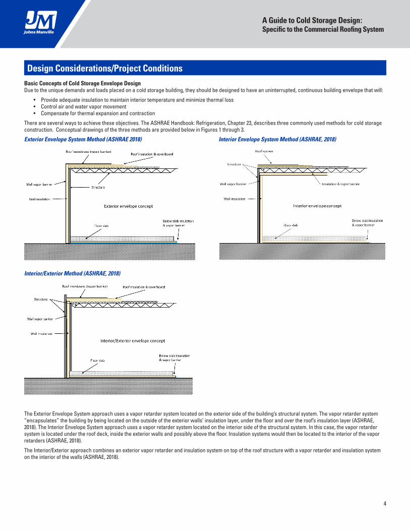
There are several ways to achieve these objectives . The ASHRAE Handbook: Refrigeration, Chapter 23, describes three commonly used methods for cold storage construction . Conceptual drawings of the three methods are provided below in Figures 1 through 3 .
Exterior Envelope System Method (ASHRAE 2018) Interior Envelope System Method (ASHRAE, 2018)
Interior/Exterior Method (ASHRAE, 2018)
The Exterior Envelope System approach uses a vapor retarder system located on the exterior side of the building’s structural system . The vapor retarder system “encapsulates” the building by being located on the outside of the exterior walls’ insulation layer, under the floor and over the roof’s insulation layer (ASHRAE, 2018) . The Interior Envelope System approach uses a vapor retarder system located on the interior side of the structural system . In this case, the vapor retarder system is located under the roof deck, inside the exterior walls and possibly above the floor . Insulation systems would then be located to the interior of the vapor retarders (ASHRAE, 2018) .
The Interior/Exterior approach combines an exterior vapor retarder and insulation system on top of the roof structure with a vapor retarder and insulation system on the interior of the walls (ASHRAE, 2018) .
4
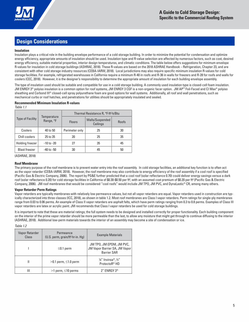
Design ConsiderationsInsulationInsulation plays a critical role in the building envelope performance of a cold storage building . In order to minimize the potential for condensation and optimize energy efficiency, appropriate amounts of insulation should be used . Insulation type and R-value selection are affected by numerous factors, such as cost, desired energy efficiency, suitable material properties, interior design temperatures, and climatic conditions . The table below offers suggestions for minimum envelope R-values for insulation in cold storage buildings (ASHRAE, 2018) . These R-values are based on the 2018 ASHRAE Handbook – Refrigeration, Chapter 23, and are consistent with other cold storage industry resources (CEBA-IARW, 2018) . Local jurisdictions may also require specific minimum insulation R-values for cold storage facilities . For example, refrigerated warehouses in California require a minimum R-40 in roofs and R-36 in walls for freezers and R-28 for roofs and walls for coolers (CEC, 2018) . However, it is the designer’s responsibility to determine the appropriate amount of insulation for each building envelope assembly .
The type of insulation used should be suitable and compatible for use in a cold storage building . A commonly used insulation type is closed-cell foam insulation . JM ENRGY 3® polyiso insulation is a common option for roof systems, JM ENRGY 3 CGF is a non-organic facer option . JM AP™ Foil-Faced and CI Max® polyiso sheathing and Corbond III® closed-cell spray polyurethane foam are good options for wall systems . Additionally, all roof and wall penetrations, such as mechanical curbs or roof hatches, and penetrations for utilities should be appropriately insulated and sealed .
Recommended Minimum Insulation R-values Table 1.1
Type of Facility Temperature Range, °F
Thermal Resistance R, °F∙ft²∙h/Btu
Floors Walls/Suspended Ceilings Roofs
Coolers 40 to 50 Perimeter only 25 30
Chill coolers 25 to 35 20 25 35
Holding freezer -10 to -20 27 35 45
Blast freezer -40 to -50 30 45 50
(ASHRAE, 2018)
Roof MembraneThe primary purpose of the roof membrane is to prevent water entry into the roof assembly . In cold storage facilities, an additional key function is to often act as the vapor retarder (CEBA-IARW, 2018) . However, the roof membrane may also contribute to energy efficiency of the roof assembly if a cool roof is specified (Pacific Gas & Electric Company, 2006) . The report by PG&E further predicted that a cool roof (solar reflectance 0 .70) could deliver energy savings versus a dark roof (solar reflectance 0 .20) for cold storage facilities in California of $0 .30-$0 .50 per ft², with an assumed cost premium of $0 .20 per ft² (Pacific Gas & Electric Company, 2006) . JM roof membranes that would be considered “cool roofs” would include JM TPO, JM PVC, and DynaLastic® CR, among many others .
Vapor Retarder Perm RatingsVapor retarders are typically membranes with relatively low permeance values, but not all vapor retarders are equal . Vapor retarders used in construction are typ-ically characterized into three classes (ICC, 2018), as shown in table 1 .2 . Most roof membranes are Class I vapor retarders . Perm ratings for single-ply membranes range from 0 .03 to 0 .06 perms . An example of Class II vapor retarders are asphalt felts, which have perm ratings ranging from 0 .3 to 0 .8 perms . Examples of Class III vapor retarders are latex or acrylic paint . JM recommends that Class I vapor retarders be used for cold storage buildings .
It is important to note that these are material ratings; the full system needs to be designed and installed correctly for proper functionality . Each building component on the interior of the prime vapor retarder should be more permeable than the last, to allow any moisture that might get through to continue diffusing to the interior (ASHRAE, 2018) . Additional low-perm materials towards the interior of an assembly may become a site of condensation or ice .
Table 1.2
Vapor Retarder Class
Permeance (U .S . perm, grain/ft²∙hr∙in . Hg) Example Materials
I ≤0 .1 permJM TPO, JM EPDM, JM PVC,
JM Vapor Barrier SA, JM Vapor Barrier SAR
II >0 .1 perm, ≤1 .0 perm ¼” Invinsa®, ½” ProtectoR® HD
III >1 perm, ≤10 perms 2” ENRGY 3®
A Guide to Cold Storage Design: Specific to the Commercial Roofing System
5
Thermal Shorts/Thermal BridgingDesigners should pay close attention to the potential for thermal shorts and thermal bridging when designing the envelope of cold storage buildings . To reduce the effects of thermal shorts in the roof system; roof insulation should be installed in at least two layers with offset joints to minimize air leakage and movement (ASHRAE, 2018) . To reduce the effects of thermal bridging, it is highly recommended that the roof membrane and upper layer(s) of rigid board insulation are adhered . Mechanical fasteners for the roof membrane or the upper layer of insulation or coverboard should be avoided as the fasteners may become sources of thermal bridging and condensation or frost . When the substrate is a steel roof deck, it is recommended that the first layer of insulation (i .e ., the layer in direct contact with the roof deck) may be mechanically attached . Remaining layers should be installed with adhesives . Induction welded plates also come with options that include a thermal break in the system . Polymer tubes break the link between the metal fastener and the induction plate and have proven effective at reducing thermal bridging in thermoplastic systems (OMG, 2018) . Example: https://omgroofing .com/sites/default/files/documents/FA1021UK_TreadSafe_EPDM_DS_A4 .pdf
For wall systems, insulated metal panels and combinations of continuous insulation (closed-cell foam boards or closed-cell spray polyurethane foams), tend to reduce thermal bridging (CEBA-IARW, 2018) . Insulation materials should be installed so as to cover structural components .
Expansion and ContractionAccommodations should be made for thermal movement in cold storage buildings . Building movement may lead to damage of a vapor retarder or a roofing system . Pipes in roofs and walls may move due to thermal expansion and contraction, as well as vibration . So, it is important to select pipe penetration flashings that can accommodate both movement and a broad temperature range, such as pre-manufactured flashing boots . Examples of some JM pipe boot options may be found at: https://www .jm .com/en/search-results/?q=boots
Execution/ApplicationIt is JM’s preference to use adhered systems in Cold Storage design . In the instances when the single-ply membrane is being used as a vapor retarder, it is highly recommended that an adhered system be used . Please refer to: “JM Complete TPO Application Guide,” “JM Complete PVC Application Guide,” and our “JM Complete EPDM Application Guide” found on our website: https://www .jm .com/en/commercial-roofing/tpo-design-and-installation-considerations/; https://www .jm .com/en/commercial-roofing/pvc-design-and-installation-considerations/; https://www .jm .com/en/commercial-roofing/epdm-design-and-installation-consider-ations/ . Please refer to your designer of record on the moisture control aspect specific to your system .
Re-roof or recover projects will require thorough inspection and the cooling unit must be shut down .
When a mechanically fastened system is necessary please obtain an approved assembly letter from the JM technical group 1-800-922-5922 # 3 and let them know this is for a cold storage project .
CitationsAmerican Society of Heating, Refrigerating and Air-Conditioning Engineers (ASHRAE) (2018) . ASHRAE handbook: Refrigeration . Atlanta, Ga: American Society of Heating, Refrigerating and Air Conditioning Engineers .
American Society of Heating, Refrigerating and Air-Conditioning Engineers (2017) . ASHRAE handbook: Fundamentals . Atlanta, Ga: American Society of Heating, Refrigerating and Air Conditioning Engineers .
Stefan, J ., Skelton,B ., and Thomas, G (2013) . Energy Modeling Guideline for Cold Storage and Refrigerated Warehouse Facilities . . PDF . Arlington . From https://www .gcca .org/sites/default/files/protected-docs/protdocs/EnergyGuidelines_2013-12-19 .pdf
OMG . (2018) . TreadSafe Product Specifications PDF . Agawam .
Reynolds, M . (2019) . The difference between air barriers and vapor barriers . Retrieved from https://www .ecohome .net/guides/2316/the-difference-between-air-bar-riers-and-vapor-barriers/
Wetherholt, R . (2015) . Considerations in Design and Construction of Freezer Buildings for Building Envelope Consultants . Interface, 22–26 .
Who We Are . (n .d .) . Retrieved from https://www .jm .com/en/our-company/
CEBA-IARW Guide to Effective Warehouse Design, Maintenance, and Modernization (2018) . Controlled Environment Building Association (CEBA) and International Association of Refrigerated Warehouses (IARW) .
Lekov, A ., Thompson, L ., McKane, A ., Rockoff, A ., Piette, M .A . (2009) . Opportunities for Energy Efficiency and Automated Demand Response in Industrial Refrigerat-ed Warehouses in California . Lawrence Berkeley National Laboratory, Report LBNL-1991E .
Pacific Gas and Electric Company (2007) . Codes and Standards Enhancement Initiative (CASE):Final Report Refrigerated Warehouses .
International Code Council . (2018) . International building code . Falls Church, Va . : International Code Council .
California Energy Commission (CEC) . (2018) . 2019 Building energy efficiency standards for residential and nonresidential buildings .
A Guide to Cold Storage Design: Specific to the Commercial Roofing System
6
717 17th St, Denver, CO 80202
(800) 922-5922
www.jm.com/roofing
@JMRoofingSystem
JohnsManvillevideos
www .jmroofing .news
facebook .com/JohnsManville
One manufacturer, one full-system guaranteeJohns Manville offers one of the most comprehensive guarantees in the
roofing industry. That’s the advantage you can expect from a financially
stable, dependable leader that has been around for over 160 years.
RS-7871 2-21 (New) © 2021 Johns Manville . All rights reserved .


![Cold storage [jkvs]](https://static.fdocuments.us/doc/165x107/5886509a1a28ab32768b721f/cold-storage-jkvs.jpg)