A GUIDE Net Zero Carbon Healthcare - Arup
24
Net Zero Carbon Healthcare A GUIDE
Transcript of A GUIDE Net Zero Carbon Healthcare - Arup

Net Zero Carbon Healthcare
A G U I D E

Contents

Net Zero and the NHS T H E E M I S S I O N S C H A L L E N G E
Building design in the UK faces an unprecedented challenge to reduce the impact of construction and operation on the environment. In June 2019 the UK Government passed a law to require the UK to end its contribution to global warming by 2050, with all greenhouse gases to be net zero by this date. This means significantly reducing the carbon emissions, as well as offsetting carbon.
For its part, the NHS has committed to a ‘Greener NHS’, aiming towards net zero. Many trusts have already published their sustainability strategies supporting a progression to net zero by 2050 or before.
T H E I N V E S T M E N T C O N T E X T
The healthcare system in the UK is responsible for an estimated 4 to 5% of the country’s carbon footprint1. In 2019, the UK Government pledged to the construction of 40 new hospitals within the UK. The Health Infrastructure Plan (HIP)2 capital investment programme is unprecedented, but also creates significant challenges in aligning with the net zero carbon aspirations.
Aside from the HIP building projects, the many existing healthcare facilities face the challenges of significant maintenance issues, historic infrastructure and buildings, and a lack of capital. This can make it difficult to implement changes designed to achieve a reduction in operational emissions.
T H E R E S P O N S E
This guide considers an approach to the design of net zero carbon healthcare buildings, providing a framework for building design to have the greatest impact on the embodied and operational carbon. It covers:
W H AT N E T Z E R O C A R B O N M E A N S
W H AT C O N T R I B U T E S T O O P E R AT I O N A L C A R B O N A N D R E L AT E D C O N S I D E R AT I O N S
W H AT C O N T R I B U T E S T O E M B O D I E D C A R B O N A N D R E L AT E D C O N S I D E R AT I O N S
H O W W E C A N C H A L L E N G E T H E N O R M
1 https://www.england.nhs.uk/greenernhs/ 2 https://assets.publishing.service.gov.uk/government/uploads/system/uploads/attachmentdata/file/835657/health-infrastructure-plan.pdf
3/2
4

Reduce Construction Impacts
Reduce Operational Energy Use
Increase Renewable Energy Supply
Offset Any Remaining Carbon
Net Zero Carbon - Construction
Net Zero Carbon - Operational Energy
A whole life carbon assessment should be undertaken and disclosed for all construction projects to drive carbon reductions.
Reductions in energy demand and consumption should be prioritised over all other measures.
On-site renewable energy source should be prioritised.
Any remaining carbon should be offset using a recognised offsetting framework.
The embodied carbon impacts from the product and construction stages should be measured and offset at practical completion.
In-use energy consumption should be calculated and publicly disclosed on an annual basis.
Off-site renewables should demonstrate additionality
The amount of offsets used should be publicly disclosed.
D
D
D
D
Defining Net Zero Carbon At the time of writing, the UK Green Building Council (UKGBC), framework3 defined within ‘Net Zero Carbon Buildings: A Framework Definition’, published in 2019, is considered the most appropriate route for defining zero carbon in both construction (embodied) and operation of buildings. The framework, at a high level, is as follows:
R E D U C E C O N S T R U C T I O N I M PA C T S
Follow a route to reduce construction impacts /embodied carbon.
R E D U C E O P E R AT I O N A L E N E R G Y
Critically appraise the potential operational energy demands and reduce through a holistic design approach.
U S E R E N E W A B L E E N E R G Y
Use renewable technologies to reduce the carbon creation from remaining operational energy use.
O F F S E T R E M A I N I N G C A R B O N
Calculate the remaining carbon after all other measures, and offset.
UKGBC: Net Zero Carbon Buildings: A framework definition; April 20193 https://www.ukgbc.org/ukgbc-work/net-zero-carbon-buildings-a-framework-definition/
4/2
4
The Arup ApproachTo achieve a net zero building design, the engineering has to be a fundamental part of the conversation from the outset of a project.
Our approach centres around ensuring that the engineering strategies are established early. This maximises the opportunity to reduce the embodied and operational carbon of designs.
The carbon emissions that can be influenced by design decisions is shown opposite. As the project progresses, the ability to impact overall carbon reduces. In other words, our ability to make significant impacts on operational and embodied carbon diminishes the further into the building’s design decisions are made.
Challenge brief/ performance criteria
Challenge space requirements - Grids & spans
Building design - Orientation & form
Space planning
Systems design - Efficiency & green technology
Post-occupancy evaluation to tune building systems
Minimise waste - Good material specification
Material & form
B R I E F D E S I G N C O N S T R U C T I O N C O M M I S S I O N O P E R AT I O N
A B I L I T Y T O R E D U C E E M B O D I E D C A R B O N
A B I L I T Y T O R E D U C E O P E R AT I O N A L C A R B O N
5/2
4

N H S O P E R AT I O N A L C A R B O N S P L I T
P R O C U R E M E N T 6 0 - 7 0 %
T R AV E L 1 5 - 2 0 %
B U I L D I N G E N E R G Y 2 0 - 2 5 %
Operational CarbonOperational carbon is divided into regulated and unregulated carbon emissions.
Regulated carbon emissions are covered within Part L of UK Building Regulations. Within a healthcare setting the embodieds can be circa 20% to 25% of the operational carbon.
Unregulated carbon emissions within a healthcare setting are a significant proportion of the NHS’s emissions. Typically, the procurement and travel components of carbon make up circa 75% to 85% of total operational carbon.
O P E R AT I O N A L C A R B O N S P L I T
The split of operational carbon on a non-domestic project varies depending on the type of project. These are typically:
60-70% Procurement
20-25% Energy
15-20% Travel
Good building design, masterplanning and site selection can influence the operational carbon attributed to building energy and transport.
In this section we explore how the ‘Lean Clean Green’ approach to design can have a significant impact on a healthcare building’s operational carbon.
6/2
4
Be Lean: Use less energy
Be Clean: Supply energy efficiently
Be Green: Use renewable
energy
Offset
Z E R O C A R B O N TA R G E T
E N E R G Y E F F I C I E N C Y TA R G E T
B U I L D I N G R E G U L AT I O N S
O N S I T E C A R B O N R E D U C T I O N
D E S I G N A P P R O A C H F O R R E D U C I N G O P E R AT I O N A L C A R B O N
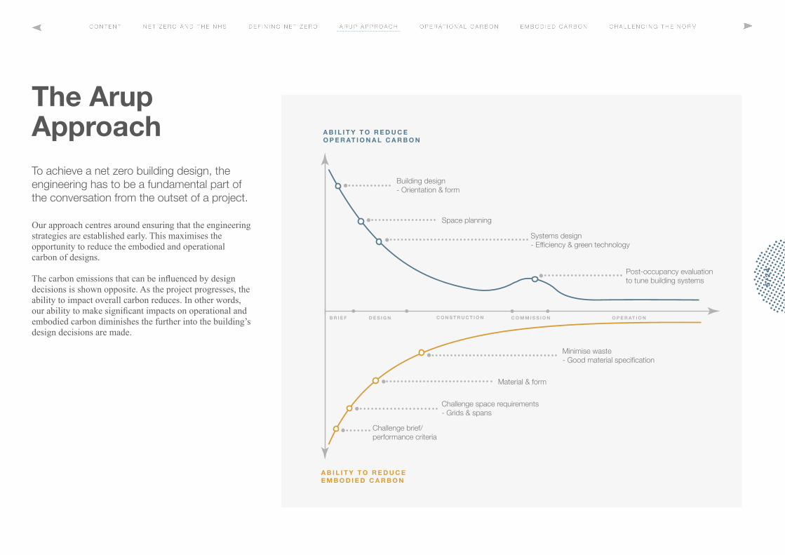
The design approachThe ‘Lean Clean Green’ approach offers a practical design framework to navigate through a project’s development to optimise the opportunity for a fully sustainable outcome. This approach is explored in more detail in this section of the guide.
Achieving net zero carbon design will require a significant carbon reduction below what is currently laid out for building energy use in Building Regulations Part L. It’s therefore important to maximise the opportunities for lower energy solutions from the inception of a project.
B E N C H M A R K I N G
The Royal Institute of British Architect’s 2030 Climate Challenge publication provides metrics for benchmarking non-domestic buildings as follows:
2020 targets < 170 kWh/m2/y
2025 targets < 110 kWh/m2/y
2030 targets < 0-55 kWh/m2/y
These targets may not apply to highly technical healthcare buildings but provide a good starting point.
O P E R AT I O N A L C A R B O N
M A N C H E S T E R P R O T O N B E A M T H E R A P Y C E N T R E
K I N G S H E A LT H PA R T N E R S H I P C A N C E R C E N T R E AT G U Y S
G U Y S T O W E R R E C L A D D I N G
J E R S E Y H O S P I TA L
Case Study:
U C L H P H A S E 4 P R O T O N B E A M T H E R A P Y C E N T R E
7/2
4
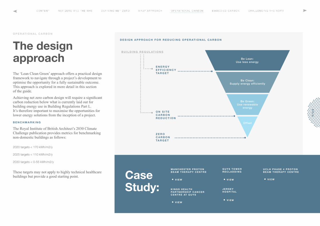
Lean DesignReducing energy consumption is essential to reduce the carbon emissions of healthcare buildings. An important first step is to consider passive design measures to prevent excessive solar gains during the summer or heat-escaping during the winter.
O P E R AT I O N A L C A R B O N
O R I E N TAT I O N A N D F O R M
The building orientation and form can have a significant impact on the ability to employ passive design measures. For example, buildings with deep plan forms can be difficult when considering natural ventilation or a mixed mode approach.
Creating spaces with depth to height ratios of between 2 and 2.5 will allow for single-sided ventilation. This works well for wards, single bedrooms and consultant spaces. Similarly, locating buildings to allow natural ventilation, with minimum solar gain, can significantly reduce the operational carbon.
O P T I M I S E S PA C E A L L O C AT I O N F O R
V E N T I L AT I O N I F P O S S I B L E
C O N S I D E R O R I E N TAT I O N A N D F O R M W I T H R E L AT I O N T O D AY L I G H T A N D S O L A R G A I N
V E N T I L AT I O N
Healthcare buildings have several highly technical spaces that demand high air-change rates to control infection. This can often lead to sealed facades with centralised mechanical ventilation supplying and extracting air.
However, there are spaces within healthcare buildings that can be designed with either natural ventilation or a mixed mode approach. An early appraisal of the proposed spatial arrangement can help maximise the opportunities for such an approach. For example, in many instances general wards, circulation spaces, offices and open-plan waiting areas can be located to avoid fully mechanical solutions reducing operational carbon emissions.
8/2
4

A well-designed building envelope should respond to external influencing factors such as orientation, climate and occupancy. Ideally it should use passive design measures to reduce the need for internal lighting, maximise natural daylighting and provide good levels of natural ventilation where appropriate.
G L A Z I N G A N D D AY L I G H T
The balance between daylighting, solar gains and artificial lighting should be considered prior to developing the façade treatment.
Solar shading can be a positive way of reducing the gains within spaces – helping to reduce operational carbon. A poorly orientated building with high glazing ratios (60-75%) may require excessive external shading to control heat-gains. On the other hand, low glazing ratios (less than 20%) may lead to an increased need for artificial lighting which can increase operational carbon.
Another consideration is that good daylighting within healthcare spaces is recognised to improve patient recovery and wellness, potentially speeding recovery and reducing the length of stay.
U - VA L U E S
A U-value quantifies the amount of heat that can transfer through a particular building fabric element. The lower the U-value the less heat is transferred. As an example, increasing the thickness of insulation in a wall build-up will reduce the amount of heat that can pass through it and hence the wall will have a lower U-value.
A good façade performance will also reduce the energy usage of the building thereby reducing carbon emissions and saving on energy bills. Optimised U-values should be challenged to avoid insulating, which could lead to over-heating or over- cooling. This can be a challenge where high internal heat- gains from key equipment are expected.
A I R L E A K A G E
With any building typology, maintaining high levels of insulation and low levels of air-leakage can reduce the heat lost to the external environment. This approach can limit the energy use, and hence carbon emissions associated with the ventilation and heating or cooling of spaces.
Achieving reduced air-leakage with a significant improvement above the limiting legislative guidance (Part L) can similarly reduce energy consumption. An optimum value of 20% improvement on Part L can be a good starting point; e.g. 2 m³/m²/hr @ 50Pa.
FA B R I C - F I R S T A P P R O A C H
C O N S I D E R I N G A I R - L E A K A G E
A N D U V VA L U E S M A X I M I S E D AY L I G H T
O P E R AT I O N A L C A R B O N
9/2
4

H E AT I N G C O O L I N G
H VA C P L A N T S I Z E
E N E R G Y O P T I M I S AT I O N
W I N D O W S I Z E
S O L A R G A I N V L I G H T
D AY L I G H T
A C O U S T I C A I R Q U A L I T Y
D AY L I G H T
G L A Z I N G A R E A
L O W E N E R G Y V E N T I L AT I O N S Y S T E M
O P E N I N G W I N D O W S
S O L A R G A I N V L I G H T
M O D E L L I N G A P P R O A C H
Balancing all these considerations to identify the most sustainable, low operational carbon solution can be challenging. At Arup, we advocate undertaking a parametric study. This study considers each of the parameters that impact on achieving a low operational carbon solution. Our ParameterSpace software can then be used to visualise the results and identify the optimal combination of inputs (e.g. glazing area or façade thermal transmittance) to achieve the required design outputs (e.g. carbon emissions and cost).
The baseline energy model is fundamental, and using parametric modelling approaches during project development ensures the initial design decisions are informed and offer the best solution.
The image on this page shows this parametric modelling approach when considering window size. Window size has implications on daylight, heating and cooling requirements, which in turn have knock-on impacts on the natural ventilation strategy, which is being explored in the blue section of the image.
S O L A R A S S E S S M E N T
Using tools to optimise the designs solutions is a very important part of the early stages of the building design process.
Tools such as ArupSolar have been developed to look at how key aspects of the building design can be adjusted in real-time to assess the impacts. This can significantly reduce the architectural/façade workflow process, allowing multiple design options in real time.
Our software assesses and develops efficient façades and glazing strategies, including solar gains, daylighting, external shading requirements and PV/solar thermal analysis.
O P E R AT I O N A L C A R B O N
10
/24

A R U P S O L A R T O O L O U T P U T
Description Cumulative Saving
0 _
B A S E L I N E Starting point – completed Stage 4 design -
1 _
O R I E N TAT I O N Adjusted orientation by 10° – to optimise heating and cooling performance 0.5-1.5%
2 _
G L A Z I N G G - VA L U E O P T I M I S AT I O N
Using parametric optimisation the g-value for the glass (the amount of solar energy the building receives) can be tested and an optimal value calculated – in this case the balance is delicate between heating and cooling loads, but a clear saving is possible
2.5-3%
3 _
U - VA L U E O P T I M I S AT I O N
Similarly to the above the thermal performance of the façade can be optimised for further savings 4.5-6%
4 _
A I R P E R M E A B I L I T Y O P T I M I S AT I O N
Air permeability optimisation – by targeting a lower air permeability a significant energy saving can be made – however there is also a balance to be struck against heating and cooling performance
11-13%
As an example, utilising our parametric design software you can see how varying the building form and facade can optimise the operational carbon, before considering the engineering systems.
O P E R AT I O N A L C A R B O N
11
/24

50%R E G U L AT E D
50%U N R E G U L AT E D
Clean design Once the building form, orientation and facade is optimised, developing a strategy to reduce remaining energy focuses on minimising energy and optimising systems. This clean design approach looks to reduce remaining energy.
As described earlier, regulated emissions / energy as 20 – 25% of operational energy. This energy use is divided into two groups: Regulated and Unregulated.
Regulated energy sources are those controlled by building regulations, as follows:
O P E R AT I O N A L C A R B O N
S PA C E H E AT I N G
H O T W AT E R
S PA C E C O O L I N G
L I G H T I N G
A U X I L I A R Y L O A D S ( P U M P S , FA N S A N D C O N T R O L S )
V E R T I C A L T R A N S P O R TAT I O N
C O M P U T E R S ,
P L U G I N D E V I C E S
L A B A N D M E D I C A L E Q U I P M E N T ( M R I , L I N A C , E T C )
C AT E R I N G E N E R G Y C O N S U M P T I O N .
Unregulated energy includes small power electricity use such as:
Unregulated energy not included within the Part L assessments can form a significant part of overall energy consumption and CO2 emissions from developments. Unregulated energy demands are included within environmental assessment methods such as BREEAM, with an emphasis on reduction.
To impact operational carbon it's important to consider these elements from the start of the project. Analysing the project brief can identify where unregulated energy demands originate.
12
/24

After implementing passive measures, the remaining systems that contribute to operational carbon emissions should be optimised.
This process should consider the primary energy use and how to reduce these demands. This can be challenging in a healthcare setting where there are significant technical spaces.
M I N I M I S I N G P R I M A R Y E N E R G Y
Minimising primary energy demand through improved system efficiency needs to look beyond regulated energy loads of fixed building services, i.e. those that are considered in Building Regulations compliance modelling.
It’s important to target unregulated loads such as medical equipment, which can be significant contributors to energy consumption and be direct sources of overheating.
Adopting the Energy Use Intensity (EUI), kWhr/m2, metric as a critical parameter assessing the overall energy consumption and efficiency of the building and benchmarking against similar buildings.
U N D E R S TA N D I N G M E D I C A L E Q U I P M E N T
Understanding the size, capacity and resilience requirements for key elements of medical equipment is critical as they can have a large unregulated energy demand, more than any other typical building typology.
P L A N T E F F I C I E N C Y
Space planning is an important part of healthcare design, where clinical function requires detailed consideration of the adjacencies of spaces. This can lead to principal plant locations being a secondary concern.
Decentralised plant is often adopted for key technical spaces, such as theatres or critical care spaces, resulting in risers and distribution losses having a negative effect on the embodied and operational carbon. For example, large risers on floor spaces increase the building area and create long distribution runs, increasing distribution losses and energy demand. Adopting a localised plant strategy may improve the operation carbon.
R E D U C I N G L I G H T I N G D E M A N D S
Reducing lighting demands can be achieved using a control system. These systems not only reduce operational demands but can also vary the output and colour of lighting throughout the day. Lighting levels and colour temperatures can be varied to mimic natural daylight patterns and give occupants the experience of a more dynamic, natural environment.
O P T I M I S E P L A N T E F F I C I E N C Y A N D
C O N S I D E R L O C AT I O N O F P L A N T
R E D U C E L I G H T I N G D E M A N D S
M I N I M I S E P R I M A R Y E N E R G Y D E M A N D
O P E R AT I O N A L C A R B O N
13
/24

Option Electricity Supply Heat Supply Cooling Supply
1 Solar Photovoltaics (PV) - Roofop installations and BIPV
2 Hydropower/Tidal Wave
3 Ground mounted and Building Integrated Wind Turbines (BIWTs)
4 Connection to EfW (private wire and heat supply)
5 Biomass Combined Heat and Power (CHP)
6 Solar Thermal
7 Deep Geothermal
8 Biomass Boiler
9 Ground Source heat Pumps (GSHPs)
10 Water Source Heat Pumps (WSHPs)
11 Air Source Heat Pumps (ASHPs)
M E T E R I N G A N D S M A R T C O N T R O L S
Smart metering and energy monitoring devices allow building managers to review energy use and optimise accordingly. This level of post-occupancy evaluation can be used to tune the systems in use and have a significant impact on overall operational carbon. In addition to overall energy usage, metering large items of plant or equipment separately can help develop an understanding of the actual power demands versus predictions, and quickly identify if optimisation is required.
The control of the heating, cooling, ventilation and lighting systems is fundamental to operational energy efficiency. To minimise energy use, buildings need to be smarter and more programmable. Using technology to create zonal and programmable heating and hot water systems allows maximum flexibility and minimises heating demand. Similarly, providing lighting that is based on occupancy can minimise unnecessary use.
L O W C A R B O N E N E R G Y S U P P LY
Avoiding onsite combustion of fossil fuels is essential in transitioning to net zero carbon.
Developing a combustion-free strategy, where heat pump technology is the primary heat source for the site, allows for a steady reduction in carbon emissions. The electricity grid continues to decarbonise and results in improved local air quality as pollutants emitted from the burning of gas are avoided. It’s also important to assess the potential role of onsite renewable generation of electricity. The ability to appropriately site renewables is a core part of this assessment; if poorly sited, the benefits of renewables reduces, particularly when the overall decarbonisation of the grid is considered.
O P E R AT I O N A L C A R B O N
14
/24
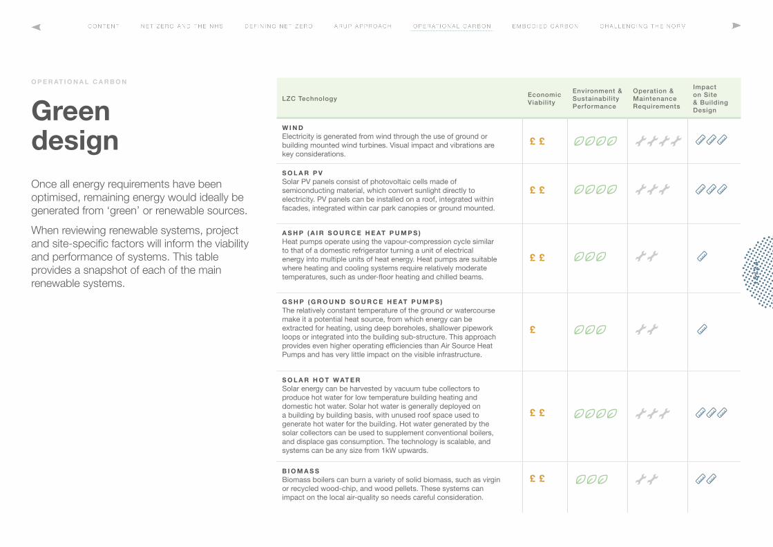
LZC Technology Economic Viability
Environment & Sustainability Performance
Operation & Maintenance Requirements
Impact on Site & Building Design
W I N D Electricity is generated from wind through the use of ground or building mounted wind turbines. Visual impact and vibrations are key considerations.
S O L A R P V Solar PV panels consist of photovoltaic cells made of semiconducting material, which convert sunlight directly to electricity. PV panels can be installed on a roof, integrated within facades, integrated within car park canopies or ground mounted.
A S H P ( A I R S O U R C E H E AT P U M P S ) Heat pumps operate using the vapour-compression cycle similar to that of a domestic refrigerator turning a unit of electrical energy into multiple units of heat energy. Heat pumps are suitable where heating and cooling systems require relatively moderate temperatures, such as under-floor heating and chilled beams.
G S H P ( G R O U N D S O U R C E H E AT P U M P S ) The relatively constant temperature of the ground or watercourse make it a potential heat source, from which energy can be extracted for heating, using deep boreholes, shallower pipework loops or integrated into the building sub-structure. This approach provides even higher operating efficiencies than Air Source Heat Pumps and has very little impact on the visible infrastructure.
S O L A R H O T W AT E R Solar energy can be harvested by vacuum tube collectors to produce hot water for low temperature building heating and domestic hot water. Solar hot water is generally deployed on a building by building basis, with unused roof space used to generate hot water for the building. Hot water generated by the solar collectors can be used to supplement conventional boilers, and displace gas consumption. The technology is scalable, and systems can be any size from 1kW upwards.
B I O M A S S Biomass boilers can burn a variety of solid biomass, such as virgin or recycled wood-chip, and wood pellets. These systems can impact on the local air-quality so needs careful consideration.
Green designOnce all energy requirements have been optimised, remaining energy would ideally be generated from ‘green’ or renewable sources.
When reviewing renewable systems, project and site-specific factors will inform the viability and performance of systems. This table provides a snapshot of each of the main renewable systems.
O P E R AT I O N A L C A R B O N
15
/24

N AT I O N A L E M B O D I E D C A R B O N S P L I T
S T R U C T U R E 4 0 - 5 0 %
F I N I S H E S 1 0 - 2 0 %
S E R V I C E S 2 0 – 3 0 %
FA C A D E S 2 0 - 3 0 %
Embodied Carbon Embodied carbon is defined as the carbon created or expended through the extraction, processing or manufacturing, transportation, construction or installation, and disposal of materials or products. Benchmarking targets is a useful first step when seeking to minimise embodied carbon.
B E N C H M A R K I N G
Benchmarking studies undertaken by Arup suggest that a lean superstructure will have an embodied carbon per square metre of circa 150 - 180 kgCO2e / m2. Superstructure embodied carbon benchmarks would be as follows:
To be avoided > 200kg CO2e/m2
Lean structure < 150kg CO2e/m2
Green structure < 100kg CO2e/m2
The RIBA 2030 climate challenge publication provides metrics for benchmarking non-domestic buildings as follows:
2020 targets < 800kg CO2e/m2
2025 targets < 650kg CO2e/m2
2030 targets < 500kg CO2e/m2
E M B O D I E D C A R B O N S P L I T
The split of embodied carbon on a non-domestic project varies depending on the type of project. Estimated splits of embodied carbon are shown above. These are typically:
40-50% Structure (including foundations)
20-30% Services
20-30% Facades
10-20% Finishes
16
/24

B U I L D N O T H I N G
B U I L D L E S S
B U I L D C L E V E R
M I N I M I S E W A S T E
The design approachWithin the structural engineering design, we propose a framework for the reduction in embodied carbon:
B U I L D N O T H I N G
Critically appraise existing building stock to determine whether there are opportunities to re-purpose.
B U I L D L E S S
Building less through maximising spatial utilisation and challenging the brief.
B U I L D C L E V E R
Use smart materials to reduce embodied carbon.
M I N I M I S E W A S T E
Use prefabrication to minimise waste on site.
E M B O D I E D C A R B O N
M A N C H E S T E R P R O T O N B E A M T H E R A P Y C E N T R E
K I N G S H E A LT H PA R T N E R S H I P C A N C E R C E N T R E AT G U Y S
G U Y S T O W E R R E C L A D D I N G
J E R S E Y H O S P I TA L
Case Study:
D E R B Y S H I R E A C U T E H O S P I TA L
17
/24

Establish the client brief
• Space allocation proposals / types
• Vibration requirements
• Loading requirements
• Environmental performance requirements
Establish the existing building form and suitability for reuse
• Building grid and column spacing
• Establish floor to floor height
• Construction type and structural elements
• Locate existing riser and services distribution
S TA G E 1
Assess the existing building form and client brief
Environmental Assessment
Undertake analysis of existing building environment and the implications of improving the thermal / energy performance of the building.
Undertake a Life-time carbon assessment to compare the period of pay-back
Structural Assessment
Undertake analysis of existing floor construction with regards to the load carrying and vibration performance.
Issue a matrix of opportunities for reuse and options for strengthening or control measures to achieve better performance
S TA G E 2
Assess capacity of the existing building— desk study and analysis
Environmental Surveys
Undertake environmental surveys that will impact on the potential for reuse
• Thermal imaging
• Air-leakage
• Noise and acoustic surveys
Structural Assessment
Surveys of existing healthcare spaces to improve the construction would include:
• Material assessment surveys (corrosion and carbonation etc)
• Vibration surveys
S TA G E 3
Specify surveys and remedial works
Build Nothing
E M B O D I E D C A R B O N The best way to reduce the embodied carbon of healthcare buildings would be to critically appraise the existing building stock and determine whether retention and adaption is an opportunity. However, healthcare buildings make the resuse of existing building stock more challenging.
By working closely with healthcare clients, to fully understand performance requirements, engineers can provide guidance on the potential to ‘flex’ requirements to make best use of existing stock. A good example of this approach is understanding how vibration performance requirements for equipment (imaging) and spaces (theatres etc) can be managed through retrofit solutions or management of the spaces.
18
/24

M I N I M I S E L O A D I N G T O S L A B S , C O N S I D E R I N G F U N C T I O N A L I T Y A N D F U T U R E F L E X I B I L I T Y
V I B R AT I O N P E R F O R M A N C E T O B E M E A S U R E D A G A I N S T C L I N I C A L F U N C T I O N E S TA B L I S H
A P P R O P R I AT E G R I D S T R U C T U R E
Build Less The ability to build less will stem from challenging the proposed brief for each space. Benchmarking against a 7.5m x 6.0m grid, the following considers the impact of varying key parameters and the impact on embodied carbon.
E S TA B L I S H R E A S O N A B L E G R I D S T R U C T U R E
Grid spacing has a significant impact on the structural solution to achieve the space performance criteria. Within a healthcare facility, the grid spacing often is dictated by the requirements of the space. These spaces have specific spatial requirements associated with clinical function i.e. ward spaces, imaging spaces etc. Changing grids to create a more efficient arrangement, having double spans or continuous structures and minimising the grids can reduce embodied carbon by up to 40%.
E F F I C I E N C Y O F S T R U C T U R A L S Y S T E M
Typically, structures require depth in order to span long distance. Flat slab construction is often adopted within a healthcare setting as it allows the separation of the structural and services zone, making distribution of services simpler and acoustic detailing easier. However, alternative structural systems, such as ribbed slabs or precast concrete systems can improve the standard solution. Our studies indicate that changing a traditional flat slab solution to a ribbed slab can reduce the carbon content by up to 5-10%.
E M B O D I E D C A R B O N M I N I M I S E L O A D I N G
The loading applied to structures has a direct impact on the structural solution. Typically, a loading of 4-5kPa would provide sufficient flexibility for a majority of spaces within a healthcare environment. However, this level of loading is often not sufficient for certain pieces of medical equipment such as imaging or medical shielding. Challenging the brief will therefore help identify where changing the applied loading to a structural slab could reduce the slab thickness and reinforcement quantities, improving the embodied carbon by up to 15-20%.
E S TA B L I S H A P P R O P R I AT E V I B R AT I O N P E R F O R M A N C E
Healthcare facilities have specific vibration performance criteria that are significantly more stringent than the performance criteria for other types of facilities. These criteria are often dictated by equipment function so cannot be varied easily. However, again, challenging the brief can help to identify where changing the vibration performance criteria can mean reduced slab thickness, in turn reducing carbon by up to 10-15%.
19
/24

U T I L I S E L O W C A R B O N M AT E R I A L S
Build CleverBuilding clever starts with ensuring that the structural system is as efficient as possible.
U S E L O W C A R B O N M AT E R I A L S
Materials, such as CLT, Glulam or timber, are considered significantly lower carbon than concrete. It is not always possible to use CLT in a healthcare setting due to the required high standards of vibration performance. However, where possible, a CLT equivalent to a concrete frame construction would significantly reduce the embodied carbon of the structure. Adopting a CLT and steel frame construction can reduce embodied carbon by up to 60%.
U S E L O W E R C A R B O N S P E C I F I C AT I O N
Using concrete, adopting cement replacement materials or steelwork with recycled content can have some impact on the embodied carbon of the material. Our studies suggest that moving away from standard CEM- 1 cement to a blended cement can reduce embodied carbon by up to 5-10%.
C O N S I D E R L O C AT I O N O F M AT E R I A L S
The geographic location and availability of materials should be considered when assessing the potential embodied carbon of the building elements.
D E S I G N F O R L O N G E V I T Y
An internal concrete frame structure would require 25mm of cover to meet corrosion requirements for 50yr design life. For superstructure elements this cover does not increase to achieve a 100yr design life. Foundations would require a greater level of cover, but over the quantum of construction this may be insignificant.
Providing a 100yr design life for the structural elements would reduce the embodied carbon per year by up to 50%. This approach would allow ‘nothing’ to be built in the future. In addition to the concept, the materials selection and specification should be carefully considered.
E M B O D I E D C A R B O N A L L O W F O R R E P U R P O S I N G
Designing for future repurposing should be considered from the start of the project, a good example of which is multi-storey car parks (MSCP). These are often required as part of the hospital infrastructure but as we strive to reduce reliance on private car-use, what becomes of the MSCP? Should such spaces be designed to allow for conversion into healthcare spaces later?
D E S I G N F O R R E - S E R V I C I N G
Another example of design for future flexibility is to develop plans that allow for easy reconfiguration or, repurposing. To support this, local plant rooms or adaptable service distribution strategies can be adopted.
20
/24

B A S E L I N E S C H E M E , 9 M X 9 M G R I D S PA C I N G , 3 0 0 M M F L AT S L A B C O N S T R U C T I O N
I N D I C AT I V E E M B O D I E D C A R B O N O P T I O N S S T U D Y
E X A M P L E K G / C O 2 E S T U D Y
Base-lines suggest that embodied carbon within healthcare building structures can range between 150kg/CO2e/m2 to 350kg/CO2e/m2.
The emphasis should be on ensuring that the structural solution is as efficient as possible, whilst maintaining the functionality and flexibility required from modern healthcare facilities.
Using our embodied carbon modelling tools, we can quickly review the implications of changing the performance parameters of the building structures. This can provide insight into how simple changes in performance requirements can have significant implications on the embodied carbon of the solution.
The example opposite shows how moving from a ward space to operating theatre using an inappropriate grid can increase the embodied carbon significantly, whereas changing the structural solution can maintain this performance and even offer a reduced embodied carbon solution.
<100 kg/CO2/M2
~150 kg/CO2/M2
>200 kg/CO2/M2
Baseline
23%
5% 5%6%
1%
12%
I N C R E A S E L O A D I N G / V I B R AT I O N P E R F O R M A N C E
F U T U R E I N C R E A S E I N V I B R AT I O N P E R F O R M A N C E
R E D U C E G R I D ( 7 . 5 X 7 . 5 M M A I N TA I N S B E T T E R P E R F O R M A N C E
L O W E R C A R B O N
C O N C R E T E
R E D U C E G R I D L O W E R C A R B O N
C O N C R E T E
A LT E R N AT I V E S T R U C T U R A L S O L U T I O N O N B A S E L I N E G R I D ( R I B B E D S L A B ) , W I T H L O W E R C A R B O N C O N C R E T E .
B E T T E R V I B R AT I O N P E R F O R M A N C E
21
/24

Minimising WasteMinimising waste in construction is important, but is not necessarily the most effective method of controlling embodied carbon. It is the last resort. Using offsite or modular construction can reduce construction waste and onsite works. However, if not properly considered, modular construction can lead to an increase in embodied carbon; with designs which focus on the efficiency of manufacturing, transportation or installation, rather than embodied carbon.
P R E FA B R I C AT I O N
Structural steelwork elements can be delivered to site in larger assemblies, subject to delivery and logistics restrictions. This typically does not impact on the materials used but can lead to additional elements. Similarly, concrete elements can be precast and delivered preassmbled. Typically, precast construction adopts higher grade material properties to allow rapid curing and lifting of components.
Prefabrication of services can also be an effective method to reduce the programme of installation of services.
Unitised facade systems can also be fabricated offsite and delivered ready for rapid assembly without the need for scaffolding or external access.
E M B O D I E D C A R B O N
P R E FA B R I C AT E FA C A D E S
P R E FA B R I C AT E R I S E R S A N D S E R V I C E S
P R E FA B R I C AT E P R I M A R Y
S T R U C T U R E
22
/24

N O R T H FA C I N G S PA C E S , A L L O W I N G P O T E N T I A L F O R
N AT U R A L V E N T I L AT I O N
S T R U C T U R A L G R I D A L I G N E D O N R E G U L A R C O N S T R A I N E D G R I D
T O M I N I M I S E E M B O D I E D C A R B O N , B U T C O N S T R A I N S P L A N N I N G
S O U T H FA C I N G , S E A L E D FA C A D E F O R T E C H N I C A L S PA C E S W I T H M E C H A N I C A L V E N T I L AT I O N
L O C A L I S E D P L A N T S PA C E T O M I N I M I S E D I S T R I B U T I O N L O S S E S A N D M A X I M I S E F L E X I B I L I T Y
Challenging the norm There are two significant conflicts that make delivery of a zero carbon healthcare building challenging, and may result in greater carbon offsetting. These are clinical planning and technical guidelines.
C L I N I C A L P L A N N I N G
Healthcare buildings are often designed to achieve the optimum adjacencies of spaces or clinical flow. These adjacencies are not arbitrary; they can be associated with patient privacy, infection control or simply ease of connection between spaces. These adjacencies can lead to spaces being located in less than optimal situations from an energy or material efficiency point of view. This can lead to solutions with greater operational and embodied carbon.
However, by working closely with clients and design collaborators, these adjacencies can be challenged to achieve solutions that balance clinical needs with achieving reductions in operational energy. Key to achieving this balance is early goal setting and a holistic design approach to facility planning.
T E C H N I C A L G U I D E L I N E S
Within the UK, technical guidance for healthcare buildings is provided within the Health Technical Memoranda (HTMs) and Health Building Note (HBN). These provide guidance on the technical performance requirements such as vibration limits, air-changes or daylighting requirements. However, it is not unusual, through the design of healthcare facilities, to derogate certain requirements to suit specific site constraints.
To achieve a low energy / zero carbon healthcare solution, challenging the norm is required. This means derogating further, which requires agreement from several key clinical stakeholders, ensuring the design remains safe and functional.
23
/24

www.arup.com/expertise/industry/healthcare
D AV E P I T M A N
D I R E C T O R
A N D R E W R O L F
A S S O C I AT E D I R E C T O R