A Graphical User Interface Framework for Formal Verification
16
A Graphical User Interface Framework for Formal Verification Edward W. Ayers DPMMS, University of Cambridge, UK Mateja Jamnik Department of Computer Science and Technology, University of Cambridge, UK W. T. Gowers DPMMS, University of Cambridge, UK Abstract We present the “ProofWidgets” framework for implementing general user interfaces (UIs) within an interactive theorem prover. The framework uses web technology and functional reactive programming, as well as metaprogramming features of advanced interactive theorem proving (ITP) systems to allow users to create arbitrary interactive UIs for representing the goal state. Users of the framework can create GUIs declaratively within the ITP’s metaprogramming language, without having to develop in multiple languages and without coordinated changes across multiple projects, which improves development time for new designs of UI. The ProofWidgets framework also allows UIs to make use of the full context of the theorem prover and the specialised libraries that ITPs offer, such as methods for dealing with expressions and tactics. The framework includes an extensible structured pretty-printing engine that enables advanced interaction with expressions such as interactive term rewriting. We exemplify the framework with an implementation for the leanprover-community fork of Lean 3. The framework is already in use by hundreds of contributors to the Lean mathematical library. 2012 ACM Subject Classification Software and its engineering → Software usability Keywords and phrases User Interfaces, ITP Digital Object Identifier 10.4230/LIPIcs.ITP.2021.4 Supplementary Material The supplementary material presented with this paper is incorporated into the leanprover-community GitHub repositories. Software (Server): https://github.com/leanprover-community/lean/tree/master/library/ init/meta/widget; archived at swh:1:dir:65d6fe171a7697793be204922aba83f2a94f5d20 Software (Client): https://github.com/leanprover/vscode-lean/blob/master/infoview/ widget.tsx; archived at swh:1:cnt:e713dbc30927867464effc1e51fd1230cd961cbd Funding Edward W. Ayers: EPSRC 1804138. Acknowledgements Enormous thanks to Gabriel Ebner and Brian Gen-ge Chen for reviewing the PRs and polishing the implementation. Also thanks for using the framework to create their own widgets, contributing and suggesting improvements: Daniel Fabian; Robert Y. Lewis; Markus Himmel; Minchao Wu; Kendall Frey; Patrick Massot. 1 Introduction Modern ITP systems such as Isabelle, Coq and Lean use advanced language servers and protocols to interface with text editors to produce a feature-rich proving experience. These systems have helpful features such as syntax highlighting and code completion suggestions as would be found in normal programming language tooling. They additionally include prover-specific features such as displaying the goal state and providing interactive suggestions © Edward W. Ayers, Mateja Jamnik, and W.T. Gowers; licensed under Creative Commons License CC-BY 4.0 12th International Conference on Interactive Theorem Proving (ITP 2021). Editors: Liron Cohen and Cezary Kaliszyk; Article No. 4; pp. 4:1–4:16 Leibniz International Proceedings in Informatics Schloss Dagstuhl – Leibniz-Zentrum für Informatik, Dagstuhl Publishing, Germany
Transcript of A Graphical User Interface Framework for Formal Verification

A Graphical User Interface Framework for FormalVerificationEdward W. Ayers !
DPMMS, University of Cambridge, UK
Mateja Jamnik !
Department of Computer Science and Technology, University of Cambridge, UK
W. T. Gowers !
DPMMS, University of Cambridge, UK
AbstractWe present the “ProofWidgets” framework for implementing general user interfaces (UIs) within aninteractive theorem prover. The framework uses web technology and functional reactive programming,as well as metaprogramming features of advanced interactive theorem proving (ITP) systems to allowusers to create arbitrary interactive UIs for representing the goal state. Users of the framework cancreate GUIs declaratively within the ITP’s metaprogramming language, without having to developin multiple languages and without coordinated changes across multiple projects, which improvesdevelopment time for new designs of UI. The ProofWidgets framework also allows UIs to makeuse of the full context of the theorem prover and the specialised libraries that ITPs offer, such asmethods for dealing with expressions and tactics. The framework includes an extensible structuredpretty-printing engine that enables advanced interaction with expressions such as interactive termrewriting. We exemplify the framework with an implementation for the leanprover-community forkof Lean 3. The framework is already in use by hundreds of contributors to the Lean mathematicallibrary.
2012 ACM Subject Classification Software and its engineering → Software usability
Keywords and phrases User Interfaces, ITP
Digital Object Identifier 10.4230/LIPIcs.ITP.2021.4
Supplementary Material The supplementary material presented with this paper is incorporated intothe leanprover-community GitHub repositories.Software (Server): https://github.com/leanprover-community/lean/tree/master/library/init/meta/widget; archived at swh:1:dir:65d6fe171a7697793be204922aba83f2a94f5d20Software (Client): https://github.com/leanprover/vscode-lean/blob/master/infoview/widget.tsx; archived at swh:1:cnt:e713dbc30927867464effc1e51fd1230cd961cbd
Funding Edward W. Ayers: EPSRC 1804138.
Acknowledgements Enormous thanks to Gabriel Ebner and Brian Gen-ge Chen for reviewing thePRs and polishing the implementation. Also thanks for using the framework to create their ownwidgets, contributing and suggesting improvements: Daniel Fabian; Robert Y. Lewis; MarkusHimmel; Minchao Wu; Kendall Frey; Patrick Massot.
1 Introduction
Modern ITP systems such as Isabelle, Coq and Lean use advanced language servers andprotocols to interface with text editors to produce a feature-rich proving experience. Thesesystems have helpful features such as syntax highlighting and code completion suggestionsas would be found in normal programming language tooling. They additionally includeprover-specific features such as displaying the goal state and providing interactive suggestions
© Edward W. Ayers, Mateja Jamnik, and W. T. Gowers;licensed under Creative Commons License CC-BY 4.0
12th International Conference on Interactive Theorem Proving (ITP 2021).Editors: Liron Cohen and Cezary Kaliszyk; Article No. 4; pp. 4:1–4:16
Leibniz International Proceedings in InformaticsSchloss Dagstuhl – Leibniz-Zentrum für Informatik, Dagstuhl Publishing, Germany

4:2 A Graphical User Interface Framework for Formal Verification
of tactics to apply in proof construction. ITP offers some additional GUI1 challenges abovewhat one might find in developing an editor extension for a standard programming language,because the process of proving is inherently interactive: the user is constantly observing thegoal state of the prover and using this information to inform their next command in theconstruction of a proof.
During research into new ways of interacting within Lean 3 theorem prover, we becamefrustrated with the development workflow for prototyping GUIs for ITP. Each time theinterface design changes, one needs to coordinate changes across three different codebases;the Lean core, the VSCode2 editor extension and our project directory. It became clearthat any approach to creating GUIs in which the editor code needs to be aware of thedatatypes used within the ITP metalogic is doomed to require many coordinated changesacross multiple codebases. This inspired our alternative approach; we designed a full-fledgedGUI framework in the metalogic of the ITP itself. This approach has the advantage oftightening the development loop and has more general use outside of our particular project,and across different ITP systems in general.
In this paper we present the ProofWidgets framework, which enables implementation ofUIs with a wide variety of features, for example:
Interactive term inspection: the ability to inspect the tree structure of expressions byhovering the mouse over different parts of a pretty printed expression.Discoverable tactics: interactive suggestions of available tactics for a given goal.Discoverable term rewriting: the ability to inspect the equational rewrites at a particularposition in the expression tree.Custom visualisations of structures like matrices, plots and graphs as well as renderingLATEX mathematical typesetting.The ability to implement language features such as go-to-definition for pretty-printedexpressions (as opposed to just text that appears in the editor).
Some of these features have been implemented to an extent within other provers (seeSection 5). However, ProofWidgets provides a unified, underlying framework for implementinguser interfaces in general, which can be used to implement these features in a customisable,extensible and portable way.
The contributions presented in this paper are:A new and general framework for creating portable, web-based, graphical UIs within atheorem prover.A functional API for creating widgets within the meta-programming framework of atheorem prover.An implementation of this framework for the Lean theorem prover.A new representation of structured expressions for use with widgets.A description and implementation of a goal-state widget used to interactively show andexplore goal states within the Lean theorem prover.
This paper is structured as follows. In Section 2 we provide an overview of some back-ground topics to contextualise the work. Section 3 details the design goals and specificationof the ProofWidgets framework. Section 4 presents the ProofWidgets implementation forLean 3. Section 5 discusses related approaches. Section 6 is the conclusion and containssome potential ideas for future work and extensions to the framework.
1 Graphical User Interface2 Visual Studio Code code.visualstudio.com
E. W. Ayers, M. Jamnik, and W. Gowers 4:3
2 Background
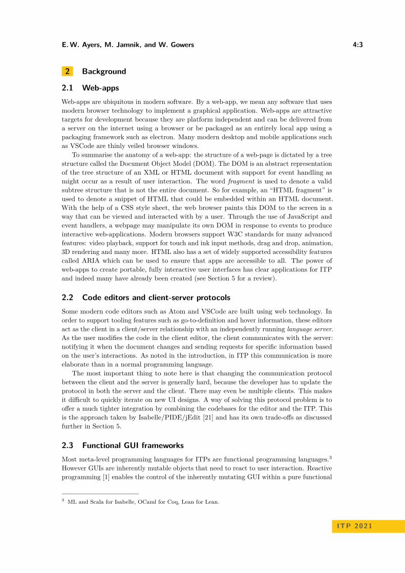
2.1 Web-appsWeb-apps are ubiquitous in modern software. By a web-app, we mean any software that usesmodern browser technology to implement a graphical application. Web-apps are attractivetargets for development because they are platform independent and can be delivered froma server on the internet using a browser or be packaged as an entirely local app using apackaging framework such as electron. Many modern desktop and mobile applications suchas VSCode are thinly veiled browser windows.
To summarise the anatomy of a web-app: the structure of a web-page is dictated by a treestructure called the Document Object Model (DOM). The DOM is an abstract representationof the tree structure of an XML or HTML document with support for event handling asmight occur as a result of user interaction. The word fragment is used to denote a validsubtree structure that is not the entire document. So for example, an “HTML fragment” isused to denote a snippet of HTML that could be embedded within an HTML document.With the help of a CSS style sheet, the web browser paints this DOM to the screen in away that can be viewed and interacted with by a user. Through the use of JavaScript andevent handlers, a webpage may manipulate its own DOM in response to events to produceinteractive web-applications. Modern browsers support W3C standards for many advancedfeatures: video playback, support for touch and ink input methods, drag and drop, animation,3D rendering and many more. HTML also has a set of widely supported accessibility featurescalled ARIA which can be used to ensure that apps are accessible to all. The power ofweb-apps to create portable, fully interactive user interfaces has clear applications for ITPand indeed many have already been created (see Section 5 for a review).
2.2 Code editors and client-server protocolsSome modern code editors such as Atom and VSCode are built using web technology. Inorder to support tooling features such as go-to-definition and hover information, these editorsact as the client in a client/server relationship with an independently running language server.As the user modifies the code in the client editor, the client communicates with the server:notifying it when the document changes and sending requests for specific information basedon the user’s interactions. As noted in the introduction, in ITP this communication is moreelaborate than in a normal programming language.
The most important thing to note here is that changing the communication protocolbetween the client and the server is generally hard, because the developer has to update theprotocol in both the server and the client. There may even be multiple clients. This makesit difficult to quickly iterate on new UI designs. A way of solving this protocol problem is tooffer a much tighter integration by combining the codebases for the editor and the ITP. Thisis the approach taken by Isabelle/PIDE/jEdit [21] and has its own trade-offs as discussedfurther in Section 5.
2.3 Functional GUI frameworksMost meta-level programming languages for ITPs are functional programming languages.3However GUIs are inherently mutable objects that need to react to user interaction. Reactiveprogramming [1] enables the control of the inherently mutating GUI within a pure functional
3 ML and Scala for Isabelle, OCaml for Coq, Lean for Lean.
ITP 2021
4:4 A Graphical User Interface Framework for Formal Verification
programming interface.4 The ideas of reactive programming have achieved a wide levelof adoption in web-app development thanks to the React JavaScript library and the Elmprogramming language [6].
The programming model used by these reactive frameworks is to model a user interfaceas a pure view function from a data source (e.g., a shopping list) to a DOM tree and anupdate function for converting user input events to a new version of the data (e.g., addingan item to the shopping list). Once the update function is applied and the data has beenupdated, the system reevaluates the view function on the new data and mutates the DOM toupdate. Although this may sound inefficient - recomputing the entire tree each time - thereis an optimisation available: if the view function contains nested view functions, one canmemoise these functions and avoid updating the parts of the DOM that have not changed.
A performance bottleneck in web-apps is the layout and painting stages of the browserrendering pipeline; the process by which the abstract DOM is converted to pixels on ascreen.5 One way to reduce the processing time spent on layout and painting is to minimisethe number of changes made to the DOM. Both Elm and React achieve this through use ofa “Virtual DOM” (VDOM). This is where a shadow tree isomorphic to the DOM is kept.When the data updates, the view function creates a new VDOM tree. This tree is then diffedwith the previous VDOM tree to produce a minimal set of changes to the real DOM. InReact, this diffing algorithm is called reconciliation.6
2.4 LeanLean [8] is an interactive theorem prover whose underlying logic is a dependent type theorycalled the calculus of inductive constructions. Lean verifies the correctness of proofs usingits kernel, which type-checks proof terms (terms whose type is a proposition). Most usersof Lean prove theorems using its tactic language. This language amounts to a sequenceof invocations of the tactic monad, which enables one to write proof scripts in a similarstyle to that popularised by the LCF provers [12]. Most notably for our purposes, betweeneach tactic invocation, Lean stores the goal state at that point, which amounts to a list ofcontexts and types that need to be inhabited to complete the proof. This goal state is prettyprinted and sent for viewing in the client editor as plaintext, with some additional formatting(i.e., syntax highlighting) applied in the client. Lean also allows users to write custom tacticlanguages.
3 Framework architecture
The ProofWidgets framework has the following design goals:
Programmers write GUIs using the metaprogramming framework of the ITP.Programmers are given an API that can produce arbitrary DOM fragments, includinginline CSS styles.No cross-compilation to JavaScript or WebAssembly: the GUI-generating code must run inthe same environment as the tactic system. This ensures that the user interaction handlershave full access to the tactic execution context, including the full database of definitions
4 A similar paradigm is that of functional reactive programming (FRP) first invented by Elliot [9]. This isdistinguished from general reactive programming by the explicit modelling of time.
5 See this chromium documentation entry for more information on critical paths in browser rendering.https://www.chromium.org/developers/the-rendering-critical-path
6 https://reactjs.org/docs/reconciliation.html
E. W. Ayers, M. Jamnik, and W. Gowers 4:5
and lemmas, as well as all of the metaprogramming library. In a cross-compilation basedapproach (implementation difficulty notwithstanding), the UI programmer would have tochoose which parts of this context to export to the client.To support interactively discoverable tactics, the system needs to be able to commandthe client text editor to modify its sourcetext.The pretty printer must be extended to allow for “interactive expressions”: expressionswhose tree structure may be explored interactively.Programmers should be able to create visualisations of their data.It should be convenient for programmers to be able to style their GUIs in a consistentmanner.The GUI programming model should include some way of managing local UI state, forexample, whether or not a tooltip is open.The GUI should be presented in the same output panel that the plaintext goal state waspresented in.The framework should be backwards compatible with the plaintext goal state system.Users should be able to opt out of the GUI if they do not like it or want to use a nonweb-app editor such as Emacs.
These goal specifications led us to design ProofWidgets to use a declarative VDOM-based architecture similar to that used in the Elm programming language [6] and the ReactJavaScript library. By using the same programming model, we can leverage the familiaritywith commonly used React and Elm. In the following subsections we will detail the design ofProofWidgets, starting with the UI programming model (Section 3.1) and the client/serverprotocol (Section 3.2).
3.1 UI programming modelNew user interfaces are created using the Html and Component types. A user may define anHTML fragment by constructing a member of the inductive datatype Html, which is eitheran element (e.g., <div></div>), a string or an object called a component to be discussedshortly.
These fragments can have event handlers attached to them. For example, a button couldhave an event attribute onclick (as used in Listing 1) which accepts a handler h : (Unit → α)sending the unit type to a member of some type α. When this interface is rendered in theclient and the button is clicked, the server is notified and causes the node to “emit” theelement h() : α. The value of h() is then propagated towards the root of the Html tree untilit reaches a component.
A component is an inductive datatype taking two type parameters: π (the props type)and α (the action type).7 It represents a stateful object in the user interface tree where thestate s : σ can change as a result of a user interaction event. By “stateful” we mean an objectwhich holds some mutating state for the lifetime of the user interface. Through the use ofcomponents, it is possible to describe the behaviour of this state without having to leave theimmutable world of a pure functional programming language. Three functions determine thebehaviour of the component:
init : π → σ initialises the state.view : π → σ → Html α maps the state to a VDOM tree.
7 This is designed to be familiar to those who use React components https://reactjs.org/docs/components-and-props.html.
ITP 2021
4:6 A Graphical User Interface Framework for Formal Verification
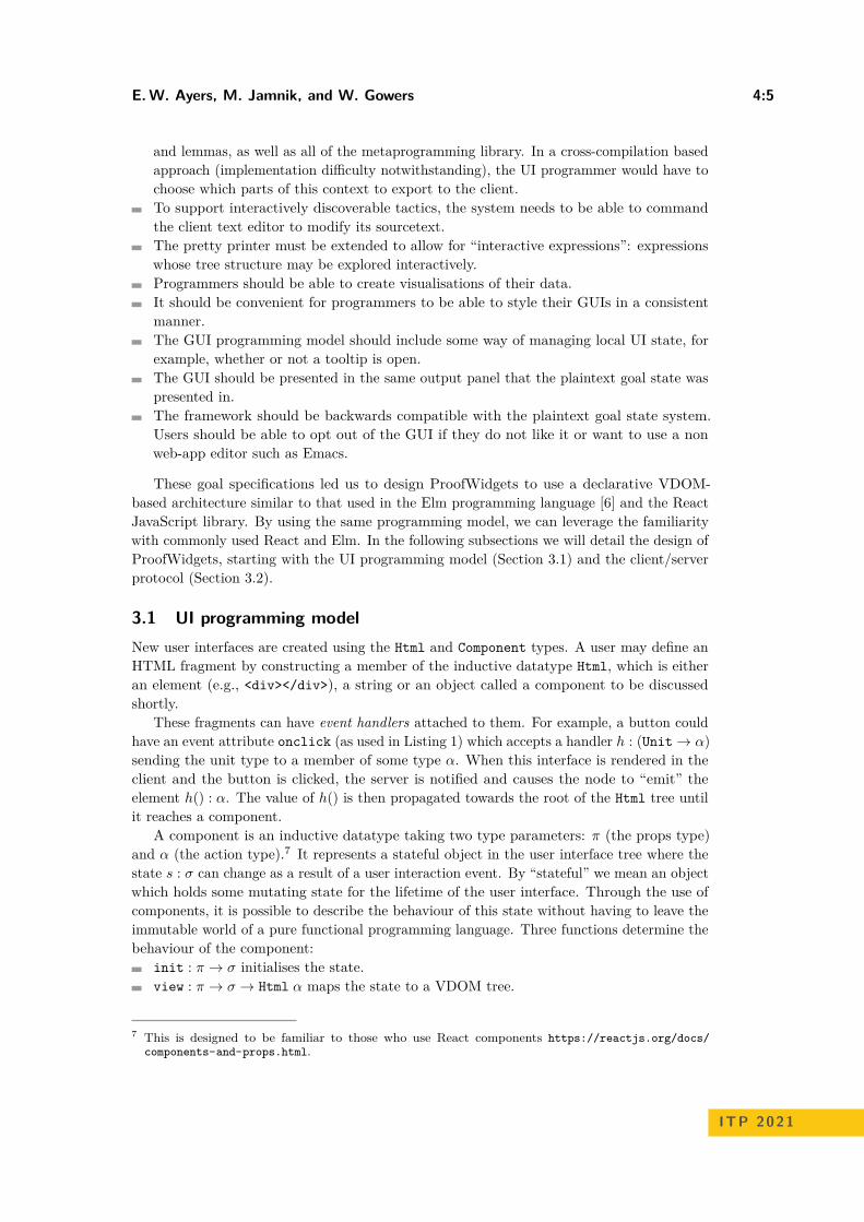
Figure 1 The output rendering of counter created in Listing 1.
update : π → α → σ → σ × Option β is run when a user event is triggered in thechild HTML tree returned by view. The emitted value a : α is used to produce a tupleσ × Option β consisting of a new state s : σ and optionally, a new event b : β to emit. Ifthe new event is provided, it will propagate further towards the root of the VDOM treeand be handled by the next component in the sequence.
For example, a simple counter component (see Listing 1 and Figure 1) has an integer s fora state, and updating the state is done through clicking on the “increment” and “decrement”buttons which will emit 1 and −1 when clicked. The values a are used to update the state toa + s. Creating stateful components in this way has a variety of practical uses when buildinguser interfaces for inspecting and manipulating the goal state. We will see in Section 4.1 thata state is used to represent which expression the user has clicked. Indeed, an entire tacticstate can be stored as the state of the component. Then the update function runs varioustactics to update the tactic state and output the new result.
Listing 1 Pseudocode listing showing a simple counter app showcasing statefulness. The outputis shown in Figure 1.counter : Component Unit Emptycounter := with_state
( init = (p 7→ 0), view = (p 7→ i 7→
<div ><button onclick =() 7→ 1>" increment "</ button >i
<button onclick =() 7→ −1>" decrement "</ button ></div >)
, update = (p 7→ a 7→ s 7→ (a + s, none)))
3.2 Client/server protocolOnce the programmer has built an interface using the API introduced in Section 3.1, itneeds to be rendered and delivered to the browser output window. ProofWidgets extends thearchitecture discussed in Section 2.2 with an additional protocol for controlling the life-cycleof a user interface rendered in the client editor (Figure 2). When a sourcefile for the proveris opened (in Figure 2, myfile.lean), the server begins parsing, elaborating and verifyingthis sourcefile as usual. The server incrementally annotates the sourcetext as it is processedand these annotations are stored in memory. The annotations include tracing diagnosticsmessages as well as thunks8 of the goal states at various points in a proof. When the user
8 A thunk is a lazily evaluated expression.

E. W. Ayers, M. Jamnik, and W. Gowers 4:7
start compilation, generate
annotations
Web Client (eg VSCode) Server (eg Lean)
get annotations at position
initialize component to
VDOM
annotations
render VDOMupdate DOMdisplay HTML
myfile.lean
open document sync
text cursor move i nf o
ok
interact
check if widget available
find event handler id
update component,
reconcile VDOM
render VDOM
wi dget _event
update DOMdisplay
process effects
ok
myfile.lean
get _wi dget
okdisplay text(pre-widget version)
ProofWidgets protocol
previously existing protocol
VDOM
Figure 2 The architecture of the ProofWidgets client/server communication protocol. Arrowsthat span the dividing lines between the client and server components are API requests and responses.The contribution of this paper is present in the section marked “ProofWidgets protocol”. The arrowscrossing the boundary between the client and server applications are sent in the form of JSONmessages. Rightward arrows are requests and leftward arrows are responses.
clicks on a particular piece of sourcecode in the editor (“text cursor move” in Figure 2),the client makes an info request for this position to the server, which responds with an okresponse containing the logs at that point.
The ProofWidgets protocol extends the info messages to allow the prover to similarlyannotate various points in the document with VDOM trees as introduced in Section 2.3. Theseannotating components have the type Component TacticState Empty where TacticStateis the current state of the prover and Empty is the uninhabited type. A default componentfor rendering goals of proof scripts is provided, but users may override this with their owncomponents. The VDOM trees are derived from this component, where the VDOM has thesame tree structure as the Html datatype (i.e., a tree of elements, strings and components),but the components in the VDOM tree also contain the current state and the current childsubtree of the component. This serves the purpose of storing a model of the current state ofthe user interface. These VDOMs can be rendered to HTML fragments that are sent to theclient editor and presented in the editor’s output window.
There are two ways to create a VDOM tree from a component: from scratch usinginitialisation or by updating an existing VDOM tree using reconciliation.
ITP 2021

4:8 A Graphical User Interface Framework for Formal Verification
Initialisation is used to create a fresh VDOM tree. To initialise a component, the systemfirst calls init to produce a new state s. s is fed to the view method to create an Htmltree t. Any child components in t are recursively initialised.
The inputs to reconciliation are an existing VDOM tree v and a new Html tree t. t iscreated when the view function is called on a parent component. The goal of reconciliationis to create a new VDOM tree matching the structure of t, but with the component statesfrom v transferred over. The tree diffing algorithm that determines whether a state should betransferred is similar to the React reconciliation algorithm9 and so we will omit a discussionof the details here. The main point is that when a user interface changes, the states of thecomponents are preserved to give the illusion of a mutating user interface.
For interaction, the HTML fragment returned from the server may also contain eventhandlers. Rather than being calls to JavaScript methods as in a normal web-app, the clienteditor intercepts these events and forwards them to the server using a widget_event request.The server then updates the component according to the event to produce a new Html treethat is reconciled with the current VDOM tree. The ProofWidgets framework then respondswith the new HTML fragment derived from the new VDOM tree. In order to ensure thatthe correct event handler is fired, the client receives a unique identifier for each handler thatis present on the VDOM and returns this identifier upon receiving a user interaction. So, ineffect, the ITP server performs the role of an event handler: processing a user interaction andthen updating the view rendered to the screen accordingly. In addition to updating the view,the response to a widget_event request may also contain effects. These are commands tothe editor, for example revealing a certain position in the file or inserting text at the cursorposition. Effects are used to implement features such as go-to definition and modifying thecontents of sourcefiles in light of a suggested modification to advance the proof state. If asecond user interaction event occurs while the first is being handled, the server will queuethese events.
The architecture design presented above is a different approach to how existing toolshandle the user interface. It offers a much smaller programming API consisting of Componentand Html and a client/server protocol that supports the operation of arbitrary user interfacescontrolled by the ITP server. Existing tools (Section 5) instead give fixed APIs for interactionwith the ITP, or support rendering of custom HTML without or with limited interactivity.
To implement ProofWidgets for an ITP system, it is necessary to implement the threesubsystems that have been summarised in this section: a programming API for components;the client editor code (i.e., the VSCode extension) that receives responses from the serverand inserts HTML fragments to the editors output window; and the server code to initialise,reconcile and render these components.
4 Implementation and applications
In this section, we present the Lean implementation of ProofWidgets and discuss a set ofexample widgets for interacting with proof objects.
The VSCode extension for Lean10 has an output pane called the “infoview” (the right-hand pane in Figure 3) which is configured to use the ProofWidgets protocol. This infoviewwindow runs as a sandboxed web-browser instance and uses React to manage updating the
9 https://reactjs.org/docs/reconciliation.html10 https://github.com/leanprover/vscode-lean
E. W. Ayers, M. Jamnik, and W. Gowers 4:9
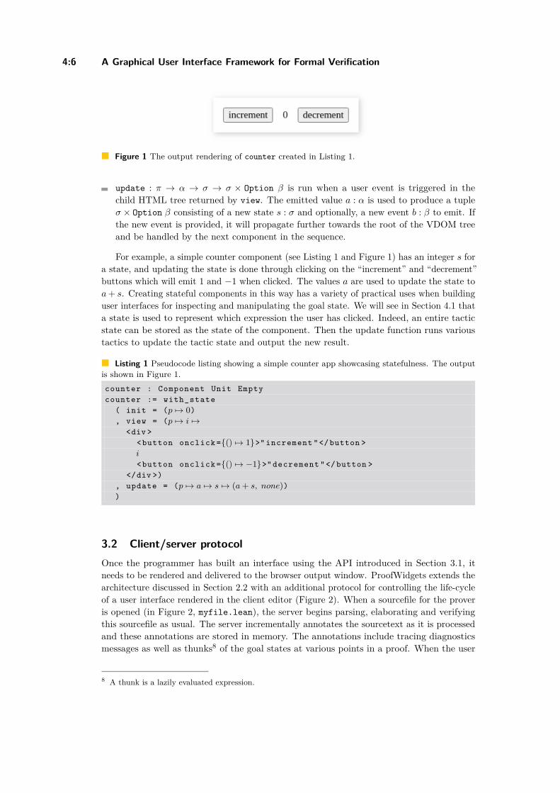
Figure 3 Screenshot showing the interactive expression view in action within the Lean theoremprover. The left-hand pane is the Lean source document and the right-hand pane is the infoviewshowing the context and expected type at the editor’s cursor. There are two nested tooltips; onegiving information about an expression in the infoview and the other on an expression within thefirst tooltip. The information that the tooltip provides is customisable, currently showing the typeof the expression and a list of implicit arguments for the given expression.
DOM based on the HTML fragments received from the server. Lean ProofWidgets can alsowork over remote proving sessions (where the client editor is running on a different machineto the ITP server, possibly in another country).
4.1 Interactive ExpressionsBy “interactive expressions” we mean augmenting a printed expression string with a mappingstructure such that the software can determine the correspondence between substrings andsubexpressions. This mapping can then be used to create interactive term inspectors andtactics. As will be discussed in Section 5, pretty printing with this additional informationis not a novel feature, however the way in which we have designed it makes these featuresavailable for producing proofs. Richly decorating expressions returned from the prover wasfirst described by Bertot and Laurent as ’proof by pointing’ [4].
An example of the interactive expression module in action is given in Figure 3: as onehovers over the various expressions and subexpressions in the infoview, one gets semanticallycorrect highlighting for the expressions, and when you click on a subexpression, a tooltipappears containing type information. This tooltip is itself a component and so can also beinteracted with, including opening a nested tooltip.
A number of other features are demonstrated in Figure 3:Hovering over subterms highlights the appropriate parts of the pretty printed string.The buttons in the top right of the tooltip activate effects including a “go to definition”button and a “copy type to clipboard” button.Expressions within the tooltip can also be explored in a nested tooltip. This is possiblethanks to the state tracking system detailed in Section 3.2.
Note that the Lean editor already has features for displaying type information for thesource document with the help of hover info. However, this tooltip mechanism is onlytextual (not interactive) and only works on expressions that have been written in the sourcedocument. Prior to ProofWidgets there was no way to inspect expressions as they appearedin the infoview.
ITP 2021
4:10 A Graphical User Interface Framework for Formal Verification
( x ++ y) ++ [ 1, 2]
++
++
: :
: :
1
2
?
a
f
f
f
f f
f
f
f
a
a
a
a
a
a
a
x
y
[ a, a, f , a]
(a)
( ) ++ _________
++ [ , ]
x y 1 2
" ( x ++ y ) ++ [ 1 , 2 ] "
f a a
f a a f a af a
[ ]
(b)
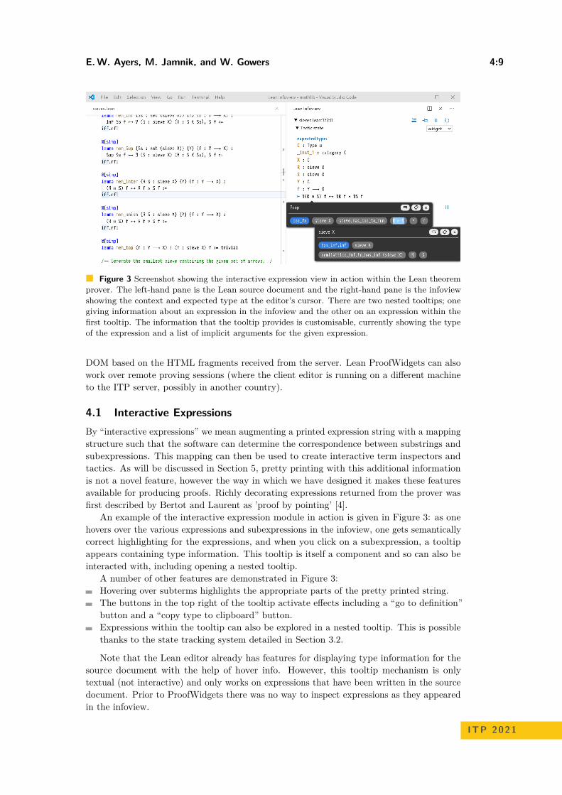
Figure 4 An expression tree for (x ++ y) ++ [1,2] is shown in Figure 4a. Each f or a above thelines is an expression coordinate. The red [a,a,f,a] example of an expression address, correspondingto the red line on the tree. Each green circle in the tree will pretty-print to a string independentof the expression tree above it. Figure 4b shows a eformat tree produced by pretty-printing theexpression (x ++ y) ++ [1,2]. The green circles are eformat.tag constructors and the blue addresstext within is the relative address of the tag in relation to the tag above it. So that means that thefull expression address for a subterm can be recovered by concatenating the Addresses above it inthe tree, for example the 2 subexpression is at [] ++ [a] ++ [a,f,a] = [a,a,f,a].
All of the code which dictates the appearance and behaviour of the infoview widget iswritten in Lean and reloads dynamically when its code is changed. This means that userscan produce their own custom tooltips and improve upon the infoview experience withintheir own Lean project.
In terms of performance, the generality of the ProofWidgets architecture means that itis possible for the user of the UI to execute long-running calculations or to render a largeVDOM. This would result in creating a sluggish UI. However, for realistic use cases, suchas producing a goal state widget as shown in Figure 3, the system should be responsive.Using the Chromium developer tools, the round trip time from a mouse pointer movementto updating the pixels on the screen was measured to be less than 80ms on an Intel i7laptop from 2012 for a goal state widget with over 1000 VDOM nodes. This means that thesystem can easily handle events that need to be responsive without requiring more advancedhardware requirements than would be needed for ITP without ProofWidgets.
To support interactive expressions, we modified the Lean pretty-printer. Prior to ourmodifications, the pretty-printer would take an expression and a context for the expressionand produce a member of the format type. This is implemented as a symbolic expressionor “sexpr” a la LISP [17]. Our modification causes the pretty-printer to instead produce aninstance of eformat. eformat is the same as format except that certain points in the sexprtree are tagged with two pieces of information: the subexpression that produced the substringand an expression address indicating where the subexpression lies in the parent expression.The expression address is a list of expression coordinates used to reference subterms of anexpression. By expression coordinate, we mean an enum that indexes the recursive argumentsin the constructors for an expression. This is visualised in Figure 4a and Figure 4b. Listing 2gives a simplified picture of the datatypes used to define expression coordinates and eformat.
The eformat tags act as a reversed source-map between the resulting sexpr and theoriginal expression. This tagging also works beneath specialised syntax such as lists [1,2,3]and set comprehensions. This tagged string is used to create ProofWidgets that allow users
E. W. Ayers, M. Jamnik, and W. Gowers 4:11
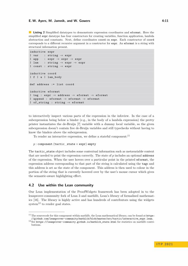
Listing 2 Simplified datatypes to demonstrate expression coordinates and eformat. Here thesimplified expr datatype has four constructors for creating variables, function application, lambdaabstraction and constants. Next, define coordinates coord on expr. Each constructor of coordcorresponds to a different recursive argument in a constructor for expr. An eformat is a string withstructural information present.inductive expr| var : string → expr| app : expr → expr → expr| lam : string → expr → expr| const : string → expr
inductive coord| f | a | lam_body
def address := list coord
inductive eformat| tag : expr → address → eformat → eformat| append : eformat → eformat → eformat| of_string : string → eformat
to interactively inspect various parts of the expression in the infoview. In the case of asubexpression being below a binder (e.g., in the body of a lambda expression) the prettyprinter instantiates the de-Bruijn [7] variable with a dummy local variable, so the givensubexpression doesn’t contain free de-Bruijn variables and still typechecks without having toknow the binders above the subexpression.
To render an interactive expression, we define a stateful component:11
p : component (tactic_state × expr) empty
The tactic_state object includes some contextual information such as metavariable contextthat are needed to print the expression correctly. The state of p includes an optional addressof the expression. When the user hovers over a particular point in the printed eformat, theexpression address corresponding to that part of the string is calculated using the tags andthis address is set as the state of the component. This address is then used to colour in theportion of the string that is currently hovered over by the user’s mouse cursor which givesthe semantic-aware highlighting effect.
4.2 Use within the Lean communityOur Lean implementation of the ProofWidgets framework has been adopted in to theleanprover-community fork of Lean 3 and mathlib, Lean’s library of formalised mathemat-ics [16]. The library is highly active and has hundreds of contributors using the widgetssystem12 to render goal states.
11 The sourcecode for this component within mathlib, the Lean mathematical library, can be found at https://github.com/leanprover-community/mathlib/blob/master/src/tactic/interactive_expr.lean.
12 See https://leanprover-community.github.io/mathlib_stats.html for statistics on mathlib contri-butions.
ITP 2021
4:12 A Graphical User Interface Framework for Formal Verification
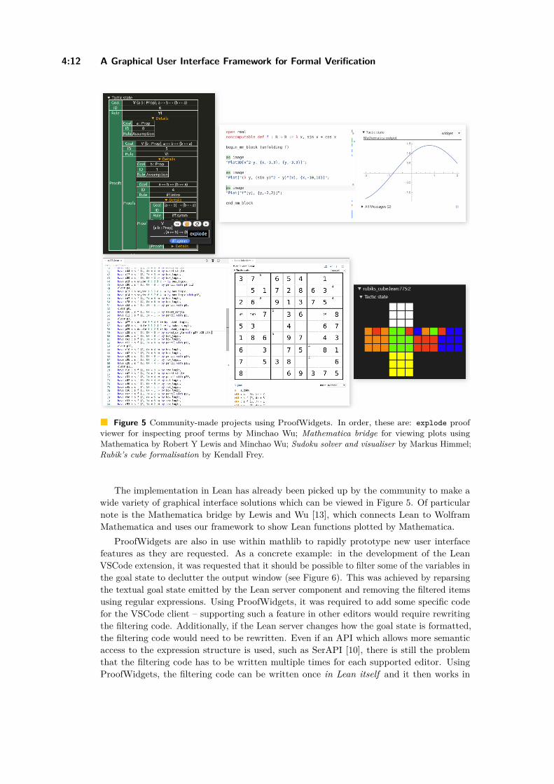
Figure 5 Community-made projects using ProofWidgets. In order, these are: explode proofviewer for inspecting proof terms by Minchao Wu; Mathematica bridge for viewing plots usingMathematica by Robert Y Lewis and Minchao Wu; Sudoku solver and visualiser by Markus Himmel;Rubik’s cube formalisation by Kendall Frey.
The implementation in Lean has already been picked up by the community to make awide variety of graphical interface solutions which can be viewed in Figure 5. Of particularnote is the Mathematica bridge by Lewis and Wu [13], which connects Lean to WolframMathematica and uses our framework to show Lean functions plotted by Mathematica.
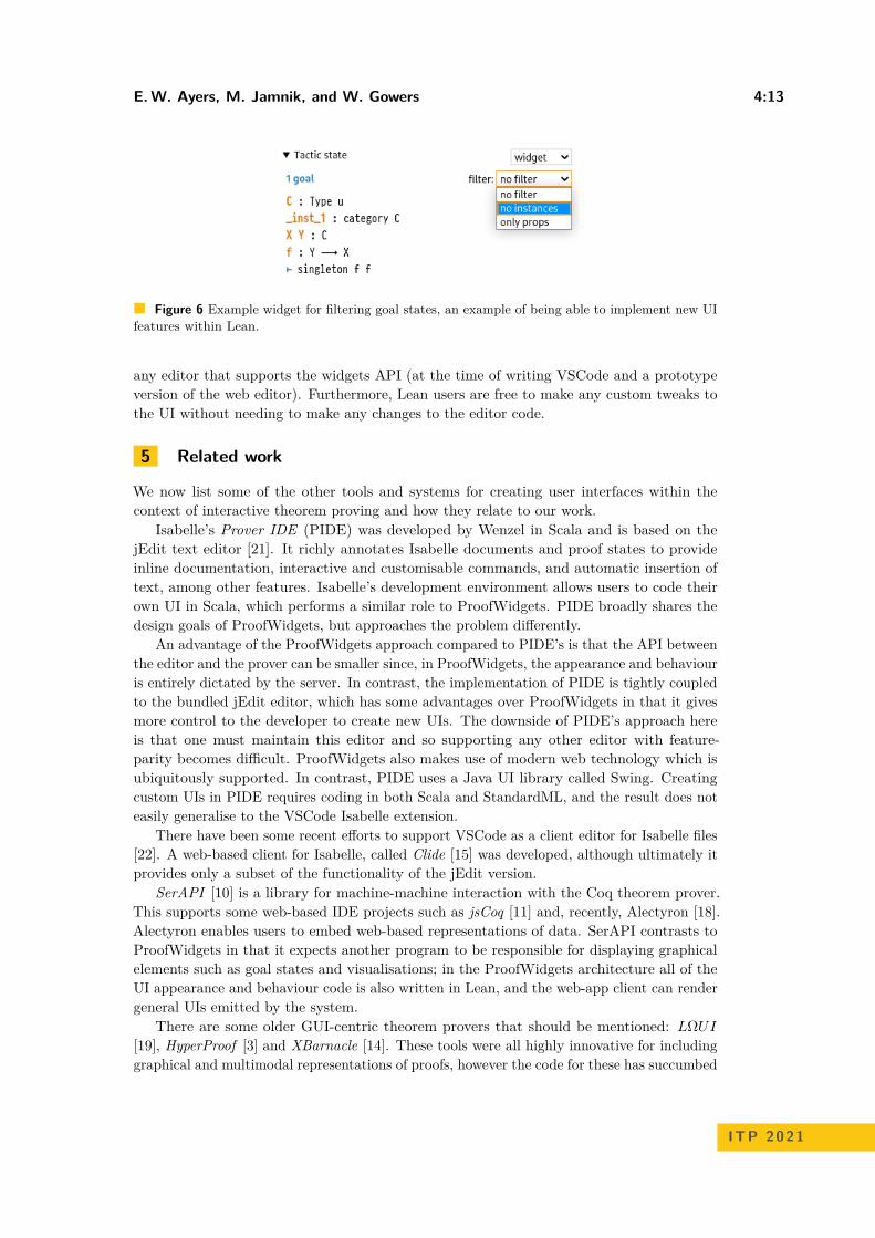
ProofWidgets are also in use within mathlib to rapidly prototype new user interfacefeatures as they are requested. As a concrete example: in the development of the LeanVSCode extension, it was requested that it should be possible to filter some of the variables inthe goal state to declutter the output window (see Figure 6). This was achieved by reparsingthe textual goal state emitted by the Lean server component and removing the filtered itemsusing regular expressions. Using ProofWidgets, it was required to add some specific codefor the VSCode client – supporting such a feature in other editors would require rewritingthe filtering code. Additionally, if the Lean server changes how the goal state is formatted,the filtering code would need to be rewritten. Even if an API which allows more semanticaccess to the expression structure is used, such as SerAPI [10], there is still the problemthat the filtering code has to be written multiple times for each supported editor. UsingProofWidgets, the filtering code can be written once in Lean itself and it then works in
E. W. Ayers, M. Jamnik, and W. Gowers 4:13
Figure 6 Example widget for filtering goal states, an example of being able to implement new UIfeatures within Lean.
any editor that supports the widgets API (at the time of writing VSCode and a prototypeversion of the web editor). Furthermore, Lean users are free to make any custom tweaks tothe UI without needing to make any changes to the editor code.
5 Related work
We now list some of the other tools and systems for creating user interfaces within thecontext of interactive theorem proving and how they relate to our work.
Isabelle’s Prover IDE (PIDE) was developed by Wenzel in Scala and is based on thejEdit text editor [21]. It richly annotates Isabelle documents and proof states to provideinline documentation, interactive and customisable commands, and automatic insertion oftext, among other features. Isabelle’s development environment allows users to code theirown UI in Scala, which performs a similar role to ProofWidgets. PIDE broadly shares thedesign goals of ProofWidgets, but approaches the problem differently.
An advantage of the ProofWidgets approach compared to PIDE’s is that the API betweenthe editor and the prover can be smaller since, in ProofWidgets, the appearance and behaviouris entirely dictated by the server. In contrast, the implementation of PIDE is tightly coupledto the bundled jEdit editor, which has some advantages over ProofWidgets in that it givesmore control to the developer to create new UIs. The downside of PIDE’s approach hereis that one must maintain this editor and so supporting any other editor with feature-parity becomes difficult. ProofWidgets also makes use of modern web technology which isubiquitously supported. In contrast, PIDE uses a Java UI library called Swing. Creatingcustom UIs in PIDE requires coding in both Scala and StandardML, and the result does noteasily generalise to the VSCode Isabelle extension.
There have been some recent efforts to support VSCode as a client editor for Isabelle files[22]. A web-based client for Isabelle, called Clide [15] was developed, although ultimately itprovides only a subset of the functionality of the jEdit version.
SerAPI [10] is a library for machine-machine interaction with the Coq theorem prover.This supports some web-based IDE projects such as jsCoq [11] and, recently, Alectyron [18].Alectyron enables users to embed web-based representations of data. SerAPI contrasts toProofWidgets in that it expects another program to be responsible for displaying graphicalelements such as goal states and visualisations; in the ProofWidgets architecture all of theUI appearance and behaviour code is also written in Lean, and the web-app client can rendergeneral UIs emitted by the system.
There are some older GUI-centric theorem provers that should be mentioned: LΩUI
[19], HyperProof [3] and XBarnacle [14]. These tools were all highly innovative for includinggraphical and multimodal representations of proofs, however the code for these has succumbed
ITP 2021
4:14 A Graphical User Interface Framework for Formal Verification
to bit rot, to the extent that they can only be viewed through the screenshots that wereincluded with the papers. Source code for Ωmega and CLAM (which LΩUI and XBarnacleuse respectively) can be found in the Theorem Prover Museum.13
Vicary’s Globular [2] and Breitner’s Incredible Proof Machine [5] also inspired our work.These tools are natively web-based and offer a visual representation of the proof state forusers to manipulate. A lot of the motivation behind ProofWidgets was to bring some of thisvisual pixiedust to a more general, heavyweight proof assistants.
6 Conclusion and future work
We designed the ProofWidgets framework: a general client/server protocol, a functional UIprogramming API and a system for tagging pretty-printed expressions. The framework isimplemented in Lean to allow for rapid development of new modalities of interaction withprovers, all within the metalanguage of Lean. This enables a faster development cycle forimproving the UI of Lean which has a direct impact on the users of ITP. We hope that thesebenefits can be brought to other interactive theorem provers in the future.
6.1 Future work
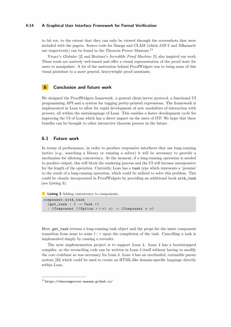
In terms of performance, in order to produce responsive interfaces that use long-runningtactics (e.g., searching a library or running a solver) it will be necessary to provide amechanism for allowing concurrency. At the moment, if a long-running operation is neededto produce output, this will block the rendering process and the UI will become unresponsivefor the length of the operation. Currently, Lean has a task type which represents a ’promise’to the result of a long-running operation, which could be utilised to solve this problem. Thiscould be cleanly incorporated in ProofWidgets by providing an additional hook with_task(see Listing 3):
Listing 3 Adding concurrency to components.component . with_task
( get_task : π → Task τ ): ( Component (( Option τ × π) α) → ( Component π α)
Here, get_task returns a long-running task object and the props for the inner componenttransition from none to some t : τ upon the completion of the task. Cancelling a task isimplemented simply by causing a rerender.
The next implementation project is to support Lean 4. Lean 4 has a bootstrappedcompiler, so the reconciling code can be written in Lean 4 itself without having to modifythe core codebase as was necessary for Lean 3. Lean 4 has an overhauled, extensible parsersystem [20] which could be used to create an HTML-like domain-specific language directlywithin Lean.
13 https://theoremprover-museum.github.io/
E. W. Ayers, M. Jamnik, and W. Gowers 4:15
References1 Engineer Bainomugisha, Andoni Lombide Carreton, Tom Van Cutsem, Stijn Mostinckx, and
Wolfgang De Meuter. A survey on reactive programming. ACM Comput. Surv., 45(4):52:1–52:34, 2013. doi:10.1145/2501654.2501666.
2 Krzysztof Bar, Aleks Kissinger, and Jamie Vicary. Globular: an online proof assistant for higher-dimensional rewriting. Log. Methods Comput. Sci., 14(1), 2018. doi:10.23638/LMCS-14(1:8)2018.
3 Jon Barwise and John Etchemendy. Hyperproof: Logical reasoning with diagrams. In WorkingNotes of the AAAI Spring Symposium on Reasoning with Diagrammatic Representations, 1992.URL: https://www.aaai.org/Papers/Symposia/Spring/1992/SS-92-02/SS92-02-016.pdf.
4 Yves Bertot and Laurent Théry. A generic approach to building user interfaces for theoremprovers. J. Symb. Comput., 25(2):161–194, 1998. doi:10.1006/jsco.1997.0171.
5 Joachim Breitner. Visual theorem proving with the incredible proof machine. In Jas-min Christian Blanchette and Stephan Merz, editors, Interactive Theorem Proving - 7thInternational Conference, ITP 2016, Nancy, France, August 22-25, 2016, Proceedings,volume 9807 of Lecture Notes in Computer Science, pages 123–139. Springer, 2016. doi:10.1007/978-3-319-43144-4_8.
6 Evan Czaplicki and Stephen Chong. Asynchronous functional reactive programming for guis.In Hans-Juergen Boehm and Cormac Flanagan, editors, ACM SIGPLAN Conference onProgramming Language Design and Implementation, PLDI ’13, Seattle, WA, USA, June 16-19,2013, pages 411–422. ACM, 2013. doi:10.1145/2491956.2462161.
7 Nicolaas Govert de Bruijn. Lambda calculus notation with nameless dummies, a tool forautomatic formula manipulation, with application to the church-rosser theorem. In IndagationesMathematicae (Proceedings), volume 75, pages 381–392. North-Holland, 1972. URL: http://alexandria.tue.nl/repository/freearticles/597619.pdf.
8 Gabriel Ebner, Sebastian Ullrich, Jared Roesch, Jeremy Avigad, and Leonardo de Moura. Ametaprogramming framework for formal verification. Proc. ACM Program. Lang., 1(ICFP):34:1–34:29, 2017. doi:10.1145/3110278.
9 Conal Elliott and Paul Hudak. Functional reactive animation. In Simon L. Peyton Jones, MadsTofte, and A. Michael Berman, editors, Proceedings of the 1997 ACM SIGPLAN InternationalConference on Functional Programming (ICFP ’97), Amsterdam, The Netherlands, June 9-11,1997, pages 263–273. ACM, 1997. doi:10.1145/258948.258973.
10 Emilio Jesús Gallego Arias. Serapi: Machine-friendly, data-centric serialization for coq. Tech-nical report, MINES ParisTech, 2016. URL: https://core.ac.uk/download/pdf/51221893.pdf.
11 Emilio Jesús Gallego Arias, Benoît Pin, and Pierre Jouvelot. jscoq: Towards hybrid theoremproving interfaces. In Serge Autexier and Pedro Quaresma, editors, Proceedings of the 12thWorkshop on User Interfaces for Theorem Provers, volume 239 of Electronic Proceedingsin Theoretical Computer Science, pages 15–27. Open Publishing Association, 2017. doi:10.4204/EPTCS.239.2.
12 Mike Gordon. From LCF to HOL: a short history. In Gordon D. Plotkin, Colin Stirling, andMads Tofte, editors, Proof, Language, and Interaction, Essays in Honour of Robin Milner,pages 169–186. The MIT Press, 2000.
13 Robert Y. Lewis. An extensible ad hoc interface between lean and mathematica. In CatherineDubois and Bruno Woltzenlogel Paleo, editors, Proceedings of the Fifth Workshop on ProofeXchange for Theorem Proving, PxTP 2017, Brasília, Brazil, 23-24 September 2017, volume262 of EPTCS, pages 23–37, 2017. doi:10.4204/EPTCS.262.4.
14 Helen Lowe and David Duncan. Xbarnacle: Making theorem provers more accessible. InWilliam McCune, editor, Automated Deduction - CADE-14, 14th International Conference onAutomated Deduction, Townsville, North Queensland, Australia, July 13-17, 1997, Proceedings,volume 1249 of Lecture Notes in Computer Science, pages 404–407. Springer, 1997. doi:10.1007/3-540-63104-6_39.
ITP 2021
4:16 A Graphical User Interface Framework for Formal Verification
15 Christoph Lüth and Martin Ring. A web interface for isabelle: The next generation. InJacques Carette, David Aspinall, Christoph Lange, Petr Sojka, and Wolfgang Windsteiger,editors, Intelligent Computer Mathematics - MKM, Calculemus, DML, and Systems andProjects 2013, Held as Part of CICM 2013, Bath, UK, July 8-12, 2013. Proceedings, volume7961 of Lecture Notes in Computer Science, pages 326–329. Springer, 2013. doi:10.1007/978-3-642-39320-4_22.
16 The mathlib Community. The lean mathematical library. In Proceedings of the 9th ACMSIGPLAN International Conference on Certified Programs and Proofs, CPP 2020, page367–381, New York, NY, USA, 2020. Association for Computing Machinery. doi:10.1145/3372885.3373824.
17 John McCarthy. Recursive functions of symbolic expressions and their computation by machine,part I. Commun. ACM, 3(4):184–195, 1960. doi:10.1145/367177.367199.
18 Clément Pit-Claudel. Untangling mechanized proofs. In Ralf Lämmel, Laurence Tratt, andJuan de Lara, editors, Proceedings of the 13th ACM SIGPLAN International Conference onSoftware Language Engineering, SLE 2020, Virtual Event, USA, November 16-17, 2020, pages155–174. ACM, 2020. doi:10.1145/3426425.3426940.
19 Jörg H. Siekmann, Stephan M. Hess, Christoph Benzmüller, Lassaad Cheikhrouhou, ArminFiedler, Helmut Horacek, Michael Kohlhase, Karsten Konrad, Andreas Meier, Erica Melis,Martin Pollet, and Volker Sorge. LOUI: Lovely omega user interface. Formal Aspects Comput.,11(3):326–342, 1999. doi:10.1007/s001650050053.
20 Sebastian Ullrich and Leonardo de Moura. Beyond notations: Hygienic macro expansion fortheorem proving languages. In Nicolas Peltier and Viorica Sofronie-Stokkermans, editors,Automated Reasoning - 10th International Joint Conference, IJCAR 2020, Paris, France, July1-4, 2020, Proceedings, Part II, volume 12167 of Lecture Notes in Computer Science, pages167–182. Springer, 2020. doi:10.1007/978-3-030-51054-1_10.
21 Makarius Wenzel. Isabelle/jedit - A prover IDE within the PIDE framework. In Johan Jeuring,John A. Campbell, Jacques Carette, Gabriel Dos Reis, Petr Sojka, Makarius Wenzel, andVolker Sorge, editors, Intelligent Computer Mathematics - 11th International Conference,AISC 2012, 19th Symposium, Calculemus 2012, 5th International Workshop, DML 2012, 11thInternational Conference, MKM 2012, Systems and Projects, Held as Part of CICM 2012,Bremen, Germany, July 8-13, 2012. Proceedings, volume 7362 of Lecture Notes in ComputerScience, pages 468–471. Springer, 2012. doi:10.1007/978-3-642-31374-5_38.
22 Makarius Wenzel. Isabelle/pide after 10 years of development. In UITP workshop: UserInterfaces for Theorem Provers., 2018. URL: https://sketis.net/wp-content/uploads/2018/08/isabellepide-uitp2018.pdf.