A global assessment of deep-sea basalt sites for carbon sequestration
8
Energy Procedia GHGT-9 A global assessment of deep-sea basalt sites for carbon sequestration David Goldberg a * and Angela L. Slagle a a Lamont-Doherty Earth Observatory of Columbia University, 61 Route 9W, Palisades, NY 10964, USA Abstract Deep-sea basalt aquifers have been identified for geological CO 2 sequestration in worldwide locations and offer vast reservoir capacities, permanent geochemical trapping potential, and other deep-sea protections that significantly reduce the risk of post- injection leakage. Using site-specific criteria, we target basalt aquifers along seismic and aseismic oceanic ridges, and calculate the injection volume potential for each. Results indicate that these aquifers occur in many oceans and could sequester 2.3–11.5 Tt-C along seismic ridges and 5.9–29.6 Tt-C along aseismic ridges. The enormous size of these potential reservoirs warrants further research and pilot experiments in each geographic setting. Keywords: ocean crust; CO2 storage; worldwide reservoirs; climate mitigation; fossil fuel emissions; energy 1. Introduction The debate over the most effective means to stabilize atmospheric greenhouse gas concentrations has supported the need for multiple approaches that require a diverse range of technologies [1-4]. The effectiveness of these methods for CO 2 sequestration depends strongly on their storage capacity, retention time, stability, and risk for leakage [5-7]. Goldberg et al. [8] present a solution for geological CO 2 sequestration in deep-sea basalt formations, an option that offers permanent geochemical trapping of CO 2 as stable, benign carbonates in a well-sealed reservoir, and multiple, low-risk protections against post-injection leakage. Very large reservoir capacities were identified in deep-sea basalt aquifers along the eastern ridge flank of the Juan de Fuca plate [8]. In this paper, we identify deep- sea basalt reservoirs with similar characteristics located along other oceanic ridge flanks around the globe and estimate their storage potential for anthropogenic CO 2 . We consider locations along the flanks of both seismic and aseismic oceanic ridges (i.e., arising from seafloor spreading or mid-plate volcanism, respectively) and use site- specific criteria such as the abundance of scientific data available (e.g., drill sites with basement penetration, permeability and/or porosity data) to evaluate each potential target region. * Corresponding author. Tel.: +1-845-365-8674; fax: +1-845-365-3182. E-mail address: [email protected]. Available online at www.sciencedirect.com c 2009 Elsevier Ltd. All rights reserved. Energy Procedia 1 (2009) 3675–3682 www.elsevier.com/locate/procedia doi:10.1016/j.egypro.2009.02.165
-
Upload
david-goldberg -
Category
Documents
-
view
212 -
download
0
Transcript of A global assessment of deep-sea basalt sites for carbon sequestration

Energy Procedia 00 (2008) 000–000
Energy Procedia
www.elsevier.com/locate/XXX
GHGT-9
A global assessment of deep-sea basalt sites for carbon
sequestration
David Goldberga* and Angela L. Slagle
a
aLamont-Doherty Earth Observatory of Columbia University, 61 Route 9W, Palisades, NY 10964, USA
Elsevier use only: Received date here; revised date here; accepted date here
Abstract
Deep-sea basalt aquifers have been identified for geological CO2 sequestration in worldwide locations and offer vast reservoir
capacities, permanent geochemical trapping potential, and other deep-sea protections that significantly reduce the risk of post-
injection leakage. Using site-specific criteria, we target basalt aquifers along seismic and aseismic oceanic ridges, and calculate
the injection volume potential for each. Results indicate that these aquifers occur in many oceans and could sequester 2.3–11.5
Tt-C along seismic ridges and 5.9–29.6 Tt-C along aseismic ridges. The enormous size of these potential reservoirs warrants
further research and pilot experiments in each geographic setting.
© 2008 Elsevier Ltd. All rights reserved
Keywords: ocean crust; CO2 storage; worldwide reservoirs; climate mitigation; fossil fuel emissions; energy
1. Introduction
The debate over the most effective means to stabilize atmospheric greenhouse gas concentrations has supported
the need for multiple approaches that require a diverse range of technologies [1-4]. The effectiveness of these
methods for CO2 sequestration depends strongly on their storage capacity, retention time, stability, and risk for
leakage [5-7]. Goldberg et al. [8] present a solution for geological CO2 sequestration in deep-sea basalt formations,
an option that offers permanent geochemical trapping of CO2 as stable, benign carbonates in a well-sealed reservoir,
and multiple, low-risk protections against post-injection leakage. Very large reservoir capacities were identified in
deep-sea basalt aquifers along the eastern ridge flank of the Juan de Fuca plate [8]. In this paper, we identify deep-
sea basalt reservoirs with similar characteristics located along other oceanic ridge flanks around the globe and
estimate their storage potential for anthropogenic CO2. We consider locations along the flanks of both seismic and
aseismic oceanic ridges (i.e., arising from seafloor spreading or mid-plate volcanism, respectively) and use site-
specific criteria such as the abundance of scientific data available (e.g., drill sites with basement penetration,
permeability and/or porosity data) to evaluate each potential target region.
* Corresponding author. Tel.: +1-845-365-8674; fax: +1-845-365-3182.
E-mail address: [email protected].
Available online at www.sciencedirect.com
c© 2009 Elsevier Ltd. All rights reserved.
Energy Procedia 1 (2009) 3675–3682www.elsevier.com/locate/procedia
doi:10.1016/j.egypro.2009.02.165

2 Goldberg/ Energy Procedia 00 (2008) 000–000
Deep-sea basalt erupts from volcanic ridges across all the world’s oceans, forming pillow lavas and lava flows on
the seafloor, and consequently, large void spaces in between them. These formations are buried over time, producing
highly permeable aquifers within the oceanic crust [9]. The advantages of these deep-sea basalt aquifers for
geological CO2 sequestration arise from providing multiple physical/chemical trapping mechanisms for CO2 injected
into the subsurface. The primary trapping mechanism involves low-permeability marine sediments that
stratigraphically seal and physically impede the migration of injected CO2 to the surface. Deep marine sediments
consist of fine-grained and impermeable calcareous oozes and clays that effectively hold fluids within underlying
aquifers over broad flanks of an oceanic ridge [e.g., 10-11]. Liquid CO2 injected into aquifers below these sediments
will be physically trapped for long periods of time. Another important trapping mechanism is geochemical or
mineral trapping, which involves reactions of CO2 with basalt to form stable carbonate minerals under in situ
conditions [12-16]. In nature, such mineralization of host rocks occurs in a variety of oceanic environments, such as
hydrothermal alteration at volcanic hot springs [17], deep-ocean vent systems [18]; and through surface weathering
[19]. Indeed, chemical weathering of basalt occurs naturally over time as the oceanic crust ages [20], permanently
depositing carbon and other infilling minerals within open pores and void spaces over millions of years [21]. Thus,
deep-sea basalt acts as a natural, in situ weathering reactor. If sufficiently open and permeable basalt is identified
below well-sealing marine sediments, then CO2 injected into these rocks would similarly be sequestered in the form
of thermodynamically stable and environmentally benign minerals [22].
The rates of these reactions depend on factors such as surface area of the rock, temperature and chemical
composition, and pH of aquifer fluids. The rate of carbonate mineral formation is known to be fast [15], so the
formation of new carbonate will depend on the release rate of ions from the dissolution of host minerals [16]. It is
likely that the CO2-basalt reaction rate will progressively decrease to a finite limit and ultimately change the
porosity and permeability within the basalt aquifer. Estimating these in situ reaction rates and accelerated effects of
carbonate precipitation will require deep-sea injection tests. Regardless, geochemical CO2-basalt processes will
proceed while CO2 is still securely trapped by physical as well as additional, secondary trapping mechanisms.
The secondary mechanisms include both gravitational trapping and hydrate trapping, which occur as a result of
physical changes in the properties of liquid CO2 when injected into the deep-sea environment. Due to the high
compressibility of liquid CO2 relative to water, CO2 becomes denser than water at high pressures and low
temperatures [11, 23-24]. Gravitational trapping occurs at ocean water depths 2700 m, where injected CO 2 is
denser than typical seawater, causing it to sink. Also, the formation of CO2 hydrate, which is a crystalline water-
based solid resembling ice, is denser and less soluble than liquid CO2 in water below 2°C [25] and thus stable below
the seabed in deep-ocean sediments [11]. Figure 1 illustrates all of the concurrent trapping mechanisms affecting
CO2 injection in a deep-sea basalt aquifer. In addition to the primary mechanisms, the secondary ones combine to
overlap in time and enhance the security of the geological storage reservoir. For deep-sea basalt aquifers that meet
Figure 1. Storage security and permanence of CO2 trapping (modified from IPCC [5]). Note uncertainty of time scales for shaded areas.
3676 D. Goldberg, A.L. Slagle / Energy Procedia 1 (2009) 3675–3682

Goldberg/ Energy Procedia 00 (2008) 000–000 3
our assessment criteria, these mechanisms provide multiple independent protective barriers that could safely isolate
the oceans and atmosphere from CO2 leakage for long periods of time.
2. Global assessment of oceanic ridges
We assess the presence of deep-sea basalt aquifers around the global ocean using four criteria: (a) the presence of
an oceanic ridge formed by seafloor spreading (seismic ridges) or by intra-plate volcanism (aseismic ridges); (b)
significant porosity in basalt aquifers (crustal ages <15 Ma for seismic ridges) and within interflow zones (for
aseimsic ridges); (c) sediment thickness of 200 m or more covering basalt crust, and (d) water depth of 2700 m or
greater at the seafloor. These criteria provide broad constraints where physical, geochemical, as well as secondary
trapping mechanisms will operate concurrently. The basalt itself provides an existing aquifer; we use published data
to estimate porosity and available reservoir capacity.
The physical properties of deep-sea basalt at mid-ocean spreading (seismic) ridges, where new ocean crust is
formed, have been well studied through geophysical and bathymetric surveys as well as through scientific drilling
and sampling [e.g., 20, 26]. The flanks of such mid-ocean ridges are known to contain highly fractured and
permeable basalt layers [e.g., 9, 27]. The natural processes of geochemical weathering in the ocean crust as it ages
reduces the initial porosity by carbonate and other infilling mineral precipitation over millions of years [21, 28].
Drilling and seismic evidence indicates that the crust retains roughly half of its initial porosity even after 15 million
years [29]. For this study, we select eleven spreading (seismic) ridge sites along segments of the global mid-ocean
ridge system in the Atlantic, Pacific, and Indian oceans (Fig. 2, green boxes). Spreading rates along these ridges
range from slow to fast spreading [30], and using these, we constrain crustal age to <15 Ma for potential reservoirs.
Deep-sea basalt also forms on the seafloor due to intra-plate volcanism (often called Large Igneous Provinces, or
LIPs) and here referred to as aseismic ridges. These are massive crystal emplacements of intrusive and extrusive
basalt that originate by processes other than seafloor spreading, including continental flood basalts, volcanic passive
margins, ocean plateaus, submarine ridges, and ocean basin flood basalts. Aseismic ridges are the most significant
global accumulations of basalt after those emplaced at seismic ridges, although their formation processes and
Figure 2. World map indicating seismic (green boxes) and aseismic ridges (blue boxes) considered in this study. Note that MAR = Mid-Atlantic
Ridge; EPR = East Pacific Rise; SWIR = Southwest Indian Ridge.
D. Goldberg, A.L. Slagle / Energy Procedia 1 (2009) 3675–3682 3677

4 Goldberg/ Energy Procedia 00 (2008) 000–000
physical properties are not as well understood [31]. McGrail et al. [15] suggest that the interbedded layers within
dense low-permeability flood basalts make them a potentially important resource for CO2 sequestration. High
porosity has been measured over thick sequences of such interbedded basalt layers on land [15, 32], although
considerably less information is available from drilling in oceanic flood basalts [31]. For this assessment, we select
seven aseismic ridges in the Atlantic, Pacific, and Indian oceans (Fig. 2, blue boxes).
The same constraints satisfying our assessment criteria are applied to both seismic and aseismic ridges, and thus,
the same concurrent trapping mechanisms apply to all sites. We analyze global sediment thickness and bathymetry
data at each seismic and aseismic ridge site using a Geographic Information System (GIS). The distribution of
sediments in the oceans is controlled by several factors, including age of the underlying oceanic crust, tectonic
history of the crust, structural trends in the basement, the nature and location of sediment sources, and the nature of
sedimentary processes delivering sediments [e.g., 33]. In general, the thickest sediments in the ocean are focused
around continental margins and at the equator. Sediment thickness data was obtained from a digital total sediment
thickness database compiled by the National Geophysical Data Center [NGDC; 34]. This database includes
information from three principle sources: previously published isopach maps, ocean drilling results, and seismic
reflection profiles archived at NGDC. NGDC data are gridded with a grid spacing of 5 arc-minutes by 5 arc-minutes
and provide a minimum value for the thickness of sediment in a particular geographic region. The Marine
Geoscience Data System (MGDS) provided ocean bathymetry, synthesized from publicly available multibeam
bathymetry data (www.marine-geo.org). For oceanic areas, MGDS merges multibeam bathymetry data with regional
lower resolution compilations, including the predicted topography of Smith and Sandwell [35]; land topography data
comes from the NASA Space Shuttle Radar Topography Mission (http://srtm.usgs.gov). We created a grid from the
global multi-resolution digital elevation model, including both low-resolution regional data and multibeam
bathymetry where available. Using the GIS, we query these data to isolate, visualize, and quantify the spatial extent
in each region that meets the necessary sediment thickness and water depth constraints. Two examples of this
analysis are presented below.
3. Seismic ridge example: Juan de Fuca Ridge
The Juan de Fuca Ridge region, a few hundred kilometers off the coast of California, Oregon and Washington in
the Pacific Ocean, is perhaps the most-studied seismic ridge in the world (Fig. 3). The flanks of the ridge are known
to contain highly fractured, channelized, and high porosity (10-15%) basalt that is covered by fine-grained turbidites
Figure 3. Example of aquifer assessment (red shading) along the east and west flanks of the Juan de Fuca Ridge (seismic). Modified from
Goldberg et al. [8]. Drilling locations shown by black dots.
3678 D. Goldberg, A.L. Slagle / Energy Procedia 1 (2009) 3675–3682
Goldberg/ Energy Procedia 00 (2008) 000–000 5
and hemipelagic clay sediments [36]. Geophysical logs and cores from the region confirm the presence of high-
angle fractures and void spaces within pillow lavas and fractured zones, alternating with massive basalt flows [8-9,
37]. Interconnectivity of such porous features yields high bulk permeability values over wide areas in this region
[32], providing considerable capacity for CO2 injection and storage.
Hydrologic studies of the Juan de Fuca region suggest vigorous hydrothermal circulation in the basement rocks
and bulk permeability estimates in the shallow crust range from 10-9
to 10-13
m2, decreasing with depth [37]. Recent
cross-hole flow experiments in basalt basement estimate lateral bulk permeability to be 10-12
m2, an order of
magnitude lower than previous estimates, which has been attributed to basement anisotropy [38]. Coupled thermal
models reproduce the overall temperature and pressure observations, with high-permeability flow channels with
lateral flow rates up to 40 m/year and the requirement that one-sixth of the ocean crust be permeable to 600 m
thickness [39]. Goldberg et al. [8] suggest that >200 Gt-C could potentially be sequestered in these basalt flow
channels on the eastern flank of the Juan de Fuca Ridge alone. Considering both eastern and western flanks
constrained by the same crustal ages, the Juan de Fuca Ridge storage region would be considerably larger (Fig. 3).
4. Aseismic ridge example: Walvis Ridge
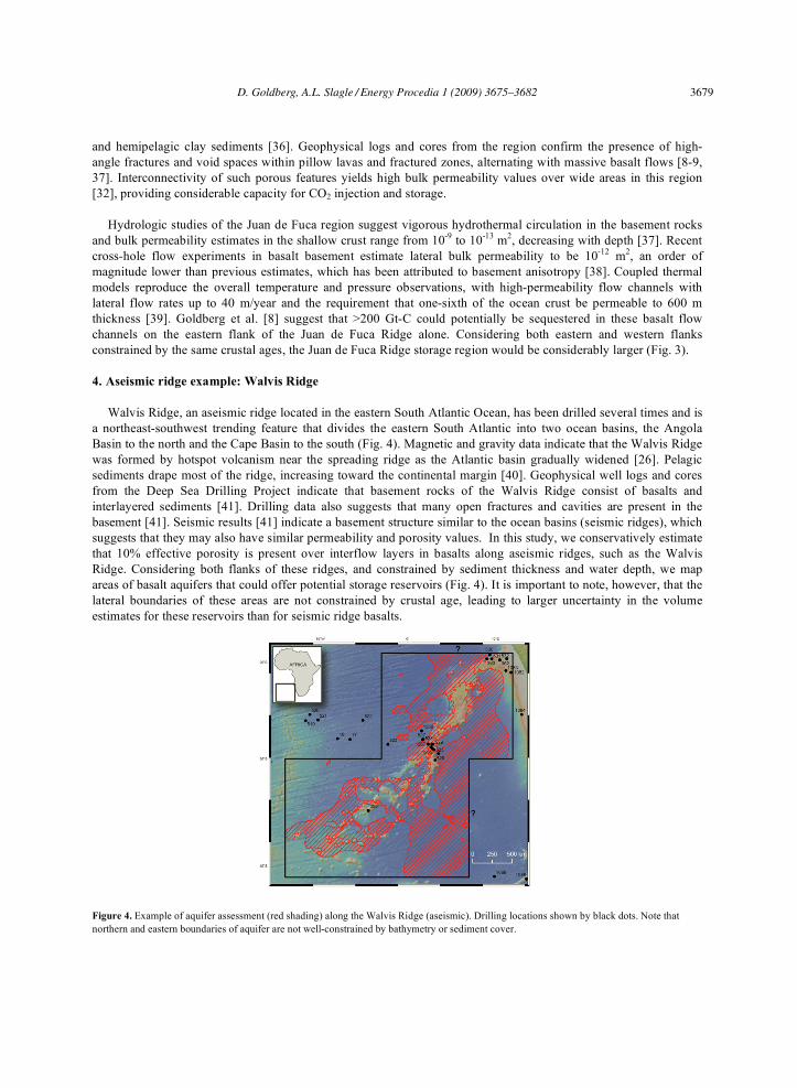
Walvis Ridge, an aseismic ridge located in the eastern South Atlantic Ocean, has been drilled several times and is
a northeast-southwest trending feature that divides the eastern South Atlantic into two ocean basins, the Angola
Basin to the north and the Cape Basin to the south (Fig. 4). Magnetic and gravity data indicate that the Walvis Ridge
was formed by hotspot volcanism near the spreading ridge as the Atlantic basin gradually widened [26]. Pelagic
sediments drape most of the ridge, increasing toward the continental margin [40]. Geophysical well logs and cores
from the Deep Sea Drilling Project indicate that basement rocks of the Walvis Ridge consist of basalts and
interlayered sediments [41]. Drilling data also suggests that many open fractures and cavities are present in the
basement [41]. Seismic results [41] indicate a basement structure similar to the ocean basins (seismic ridges), which
suggests that they may also have similar permeability and porosity values. In this study, we conservatively estimate
that 10% effective porosity is present over interflow layers in basalts along aseismic ridges, such as the Walvis
Ridge. Considering both flanks of these ridges, and constrained by sediment thickness and water depth, we map
areas of basalt aquifers that could offer potential storage reservoirs (Fig. 4). It is important to note, however, that the
lateral boundaries of these areas are not constrained by crustal age, leading to larger uncertainty in the volume
estimates for these reservoirs than for seismic ridge basalts.
Figure 4. Example of aquifer assessment (red shading) along the Walvis Ridge (aseismic). Drilling locations shown by black dots. Note that
northern and eastern boundaries of aquifer are not well-constrained by bathymetry or sediment cover.
D. Goldberg, A.L. Slagle / Energy Procedia 1 (2009) 3675–3682 3679

6 Goldberg/ Energy Procedia 00 (2008) 000–000
Table 1. Volume estimates of carbon storage potential for deep-sea basalt aquifers
Regiona Area (km
2)
b 20 m net thickness
c 100 m net thickness
c Carbon (Gt)
Juan de Fuca 244,963 490 2,450 134 – 668
East Pacific Rise 491,561 983 4,916 268 – 1,340
Cocos Ridge 891,510 1,783 8,915 486 – 2,431
Mid-Atlantic Ridge 60N 52,734 105 527 29 – 144
Mid-Atlantic Ridge 40N 139,141 278 1,391 76 – 379
Mid-Atlantic Ridge 0 220,842 442 2,208 120 – 602
Mid-Atlantic Ridge 40S 3,778 8 38 2 – 10
Southwest Indian Ridge 5E 81,329 163 813 44 – 222
Southwest Indian Ridge 45E 15,757 32 158 9 – 43
Gulf of Aden 30,763 62 308 17 – 84
Southeast Indian Ridge 2,068,304 4,137 20,683 1,128 – 5,640
Caribbean flood basalt 541,611 1,083 5,416 295 – 1,477
Rio Grande Rise 831,818* 1,664 8,318 454 – 2,268
Walvis Ridge 1,933,711* 3,867 19,337 1,055 – 5,273
Kerala Basin 952,761 1,906 9,528 520 – 2,598
Ninetyeast Ridge/Broken Ridge 2,198,757 4,398 21,988 1,199 – 5,996
Kerguelen Plateau 1,788,834* 3,578 17,888 976 – 4,878
Ontong Java Plateau 2,616,646* 5,233 26,166 1,427 – 7,136
Total Seismic Sites 2,313 – 11,564 Gt
Total Aseismic Sites 5,925 – 29,627 Gt
a Above the line are seismic ridges; below are aseismic ridges (see Fig. 2). b Asterisks indicate uncertain regional boundaries. c These calculations assume 10% average aquifer porosity. Total for All Sites 8,238 – 41,191 Gt
5. Estimating CO2 storage volume
Using our four geological constraints (a-d, Section 2) at each location identified in Figure 2, we compute the
potential carbon storage capacity for deep-sea basalt reservoirs along both seismic and aseismic ridges. The area
(km2) in each region is calculated to meet the water depth and sediment thickness constraints, as illustrated in
Figures 3 and 4. We additionally restrict our analysis in each region to avoid natural areas of fluid inflow/outflow
between the ocean and underlying basement rocks, avoiding areas within 20 km of all plate boundaries, to further
protect against the possibility of long-term CO2 leakage to the seafloor. We use 10% as a conservative estimate for
average porosity persisting in basalt aquifers, based on observations of in situ density and porosity logs from ocean
drilling sites [e.g., 14]. Then, the net aquifer thickness in ocean basalt crust is estimated to be between 20 and 100 m
over the upper few hundred meters of sediment-covered basement. These ranges define the volume available for
CO2 storage, and hence we compute a minimum and maximum value for net reservoir thicknesses, respectively. The
range of outcomes accommodates site-specific variability in the basalt structure for both seismic and aseismic ridge
types. Assuming that liquefied CO2 (CO2 density ~1 g/cm3, or 0.27 g C/cm
3) is injected to fill the aquifer volume,
and also, that all of the CO2 is eventually fixed as carbonate (CaCO3 density ~2.7 g/cm3, or 0.36 g C/cm
3), we
compute a minimum/maximum range of carbon storage capacity in each potential area. Table 1 summarizes these
computations.
The total volume potential for the eastern and western flanks of the Juan de Fuca Ridge (see Fig. 3) ranges from
134 to 668 Gt-C, representing minimum and maximum net reservoir thicknesses (20 m and 100 m, respectively).
Observations and modeling of basalt aquifers along the Juan de Fuca Ridge flanks support the higher volume
estimate [8, 39]. The total volume potential along the flanks of the Walvis Ridge (see Fig. 4) ranges from 1,055 to
5,273 Gt-C, for the same thickness estimates. Because data and observations along aseismic ridges are sparse, the
minimum thickness yields a more conservative, and potentially realistic, estimate for this location. Along seismic
ridges, the total volume potential for deep-sea basalt aquifers ranges from 2.3–11.5 Tt-C; along aseismic ridges, the
total ranges from 5.9–29.6 Tt-C. Note, however, that although the volume range for aseismic ridges is more than
twice that for seismic ridges, the aseismic area boundaries are not nearly as well-constrained and drilling data is
more sparse, which leads to greater uncertainty inherent in their volume calculations. Given these uncertainties, the
worldwide total volume potential ranges from 8.2 to 41.2 Tt-C – an enormous volume, even assuming the minimum
reservoir thickness estimates.
3680 D. Goldberg, A.L. Slagle / Energy Procedia 1 (2009) 3675–3682

Goldberg/ Energy Procedia 00 (2008) 000–000 7
6. Discussion
The technical challenges of utilizing any of these vast reservoirs for sequestration, such as pipeline transport, sub-
sea maintenance, and post-injection monitoring systems, must be quantified and evaluated. Certainly the proximity
of possible locations to accessible ports, pipelines, and potential sources of CO2 will affect their relative costs and
benefits. Our plans for future analyses will consider the practicalities of specific deep-sea reservoirs, such as those
closer to the continents and those nearer to regional CO2 sources. To begin that analysis, regional technical and
economic assessments are required, in addition to more detailed and site-specific geological research. For some
deep-sea locations, these assessments may conclude that it is acceptable to relax one or more of the geological
constraints used in this study, such as the minimum marine sediment thickness or minimum ocean water depth, as a
trade-off for a greater technical or economic advantage. For example, basalt aquifers on ridge flanks in the Gulf of
Aden could provide a storage location in close proximity to Persian Gulf CO2 sources. Table 1 indicates that the
Gulf of Aden area could support sequestration of 17-84 Gt-C under all the proposed geological constraints. If
thinner sediment cover (as little as 100 m) were considered, however, the volume of these basalt aquifers would
increase by a factor of two. Or, if shallower ocean depths (< 2700 m) were considered, the volume of these basalt
aquifers and their sequestration potential would increase by a factor of about nine. In such cases, additional risks
would result from fewer active trapping mechanisms (e.g., no gravitational trapping in shallower waters) or from
less sediment cover, however the value of avoiding such risks remains to be established. The long-term benefits of
the enormous worldwide volumes and low-risk stability of CO2 sequestered in deep-sea basalt aquifers should also
be valued in broader economic assessments.
7. Conclusions
Table 1 summarizes our assessment of deep-sea basalt aquifers as potential reservoirs for safe and secure
sequestration of anthropogenic CO2. These computations suggest that an enormous volume is available in these
reservoirs, which have been identified worldwide. The total volume potential for these aquifers ranges from 2.3–
11.5 Tt-C along seismic ridges to 5.9–29.6 Tt-C along aseismic ridges, and total between 8.2 and 41.2 Tt-C.
Although the volumes presented are broad estimations, they are based on global databases and scientific drilling
data. For greater certainty in the estimates for any particular target location, site-specific geological research and
pilot studies must be conducted locally. In particular, the Juan de Fuca Ridge, the Cocos Ridge, and the Sheba Ridge
in the Gulf of Aden, as well as the Walvis Ridge and the northern section of the Ninetyeast Ridge, offer large-
capacity storage volumes within reasonable proximity to continental margins and to potential industrial CO2
sources. The huge size of even one of these deep-sea basalt aquifers, in addition to the critical advantages for
sequestration that deep-sea basalts offer, warrants further research and investigation. Research should aim towards
pilot injection studies to address questions such as site-specific hydrological testing, the in situ reaction rates for
dissolution of injected CO2, in situ carbonate precipitation rates and the resulting rates of change in permeability.
References
1. M.I. Hoffert, K. Caldeira, G. Benford, D.R. Criswell, C. Green, H. Herzog, A.K. Jain, H.S. Kheshgi, K.S. Lackner, J.S. Lewis, H.D.
Lightfoot, W. Manheimer, J.C. Mankins, M.E. Mauel, L.J. Perkins, M.E. Schlesinger, T. Volk, T.M.L. Wigley, Advanced technology paths
to global climate stability: Energy for a greenhouse planet. Science 298 (2002) 981-987.
2. K.S. Lackner, A guide to CO2 sequestration. Science 300 (2003) 1677-1678.
3. S. Pacala and R. Socolow, Stabilization Wedges: Solving the climate problem for the next 50 years with current technologies. Science 305
(2004) 968-972.
4. K.S. Lackner and J.D. Sachs, A robust strategy for sustainable energy use. Brookings Papers on Economic Activity 2 (2005) 215-284.
5. IPCC, IPCC Special Report on Carbon Dioxide Capture and Storage. Prepared by Working Group III of the Intergovernmental panel on
Climate Change. [B. Metz, O. Davidson, H.C. deConinck, M. Loos, L.A. Meyer, eds] Cambridge Univ Press, New York (2005) 442 pp.
6. D.G. Hawkins, No exit: Thinking about leakage from geologic carbon storage sites. Energy 29 (2004) 1571-1578.
7. C.A. Rochelle, I. Czernichowski-Lauriol, A.E. Milodowski, The impact of chemical reactions on CO2 storage in geological formations: A
brief review. In Geo Stor of Carbon Dioxide [S.J. Baines, R.H. Worden, eds] Geol Soc London, London, Spec Publ 233 (2004) 87-106.
8. D. Goldberg, T. Takahashi, A.L. Slagle, Carbon dioxide sequestration in deep-sea basalt. Proc Nat Acad Sci USA 105, 29 (2008) 9920-9925.
9. A.T. Fisher, Permeability within basaltic oceanic crust. Rev Geophys 36 (1998) 143-182.
D. Goldberg, A.L. Slagle / Energy Procedia 1 (2009) 3675–3682 3681

8 Goldberg/ Energy Procedia 00 (2008) 000–000
10. H. Elderfield, C.G. Wheat, M.J. Mottl, C. Monnin, B. Spiro, Fluid and geochemical transport through oceanic crust: a transect across the
eastern flank of the Juan de Fuca Ridge. Earth Plan Sci Lett 172, 1-2 (1999) 151-165.
11. J.S. Levine, J.M. Matter, D. Goldberg, A. Cook, K.S. Lackner, Gravitational trapping of carbon dioxide in deep sea sediments: Permeability,
buoyancy, and geomechanical analysis. Geophys Res Lett 34, L24703 (2007).
12. W. Seifritz, CO2 disposal by means of silicates. Nature 345 (1990) 486.
13. B. Hitchon, Aquifer Disposal of Carbon Dioxide: Hydrodynamic and Mineral Trapping – Proof of Concept. [B. Hitchon ed] Geosci Publ
Ltd, Alberta (1996) 165 pp.
14. D. Goldberg, CO2 sequestration beneath the seafloor: Evaluating the in situ properties of natural hydrate-bearing sediments and oceanic
basalt crust. Int J Soc Mater Eng 7 (1999) 11-16.
15. B.P. McGrail, H.T. Schaef, A.M. Ho, Y.J. Chien, J.J. Dooley, C.L. Davidson, Potential for carbon dioxide sequestration in flood basalts. J
Geophys Res 111, B12 (2006).
16. J.M. Matter, T. Takahashi, D. Goldberg, Experimental evaluation of in situ CO2-water-rock reactions during CO2 injection in basaltic rocks:
Implications for geological CO2 sequestration. Geochem Geophys Geosys 8, Q02001 (2007).
17. I. Barnes and J.R. O’Neil, The relationship between fluids in some fresh Alpine-type ultramafics and possible modern serpentinization,
Western United States. Geol Soc Am Bull 80 (1969) 1947-1960.
18. D.S. Kelley, J.A. Karson, D.K Blackman, G.L. Fruh-Green, D.A, Butterfield, M.D. Lilley, E.J. Olsen, M.O. Schrenk, K.K. Roe, G.T. Lebon,
P. Rivizzigno, An off-axis hydrothermal vent field near the Mid-Atlantic Ridge at 30° N. Nature 412 (2001) 145-149.
19. C. Neal and G. Stanger, Past and present serpentinization of ultramafic rocks: An example from the Semail ophiolite nappe of northern
Ornan. In The Chemistry of Weathering [J.I. Drever ed] D Reidel Publ Co, Dordrecht, The Netherlands (1985) 249-275.
20. N. Christensen and M. Salisbury, Seafloor spreading, progressive alteration of Layer 2 basalts, and associated changes in seismic velocities.
Earth Plan Sci Lett 15 (1972) 367-375.
21. H. Staudigel, S. Hart, S. Richardson, Alteration of the ocean crust: processes and timing. Earth Plan Sci Lett 52 (1981) 311-327.
22. T. Takahashi, D. Goldberg, J.C. Mutter, Secure, long-term sequestration of CO2 in deep saline aquifers associated with oceanic and
continental basaltic rocks. Proc SRI Intl Symp, Deep Sea & CO2, The Ship Research Inst, Mitaka (2000) 4-1-1–4-1-7.
23. H. Koide, Y. Shindo, Y. Tazaki, M. Iijima, K. Ito, N. Kimura, K. Omata, Deep sub-seabed disposal of CO2 – The most protective storage.
Energ Convers Mgmt 38 (1997) S253-S258.
24. K.Z. House, D.P. Schrag, C.F. Harvey, K.S. Lackner, Permanent carbon dioxide storage in deep-sea sediments. Proc Nat Acad Sci USA 103,
33 (2006) 12291-12295.
25. P. Brewer, G. Friederich, E. Peltzer, F.M. Orr, Jr., Direct experiments on the ocean disposal of fossil fuel CO2. Science 284 (1999) 943-945.
26. P.D. Rabinowitz and E.S.W. Simpson, Geophysical site survey results on the Walvis Ridge. In Init Repts DSDP 74 [T.C. Moore et al.] US
Govt Printing Office, Washington (1984) 795-825.
27. M.G. Langseth, K. Becker, R.P. von Herzen, P. Schultheiss, Heat and fluid flux through sediment on the western flank of the mid-Atlantic
Ridge - A hydrogeological study of North Pond. Geophys Res Lett 19, 5 (1992) 517-520.
28. J. C. Alt and D. A. Teagle, The uptake of carbon during alteration of ocean crust. Geochim Cosmochim Acta 63 (1999) 1527-1525.
29. R.D. Jarrard, L.J. Abrams, R. Pockalny, R.L. Larson, T. Hirono, Physical properties of upper oceanic crust: Ocean Drilling Program Hole
801C and the waning of hydrothermal circulation. J Geophys Res 108, B4 (2003).
30. C. DeMets, R. Gordon, D. Argus, S. Stein, Current plate motions. Geophys J Int 101 (1990) 425-478.
31. M.F. Coffin and O. Eldholm, Large Igneous Provinces – Crustal structure, dimensions, and external consequences. Rev Geophys 32, 1
(1994) 1-36.
32. D. Goldberg, D. Reynolds, C. Williams, B. Witte, P. Olsen, D. Kent, Well Logging results from the Newark Basin Drilling Project.
Scientific Drilling 4, 4-6 (1994) 267-279.
33. S. Boggs, Sedimentology and Stratigraphy, Prentice-Hall, Inc, New Jersey (1995) 774 pp.
34. D.L. Divins, NGDC Total Sediment Thickness of the World’s Oceans and Marginal Seas.
http://www.ngdc.noaa.gov/mgg/sedthick/sedthick.html (retrieved 7/2007).
35. W.H. Smith and D. Sandwell, Global seafloor topography from satellite altimetry and ship depth soundings. Science 277 (1997) 1957-1962.
36. E.E. Davis and K. Becker, Borehole observatories record driving forces for hydrothermal circulation in young oceanic crust. EOS Trans Am
Geophys Union 79 (1998) 369-378.
37. A.T. Fisher, K. Becker, and E.E. Davis, The permeability of young oceanic crust east of Juan de Fuca Ridge determined using borehole
thermal measurements. Geophys Res Lett 24, 11 (1997) 1311-1314.
38. A.T. Fisher, E.E. Davis, and K. Becker, Borehole-to-borehole hydrologic response across 2.4 km in the upper oceanic crust: Implications for
crustal-scale properties. J Geophys Res 113, B7 (2008).
39. G.A. Spinelli and A.T. Fisher, Hydrothermal circulation within topographically rough basaltic basement on the Juan de Fuca Ridge flank.
Geochem Geophys Geosyst 5, Q02001 (2004).
40. T.C. Moore, Jr, P.D. Rabinowitz et al., Init Repts DSDP 74, US Govt Printing Office, Washington (1984).
41. P.D. Rabinowitz and P.E. Borella, Well logging of the sediments and basement complex on the Walvis Ridge. In Init Repts DSDP 74 [T.C.
Moore et al.] US Govt Printing Office, Washington (1984) 827-838.
3682 D. Goldberg, A.L. Slagle / Energy Procedia 1 (2009) 3675–3682


![Flexural Behaviour of Basalt Fiber Reinforced Concrete ... · Basalt rock can also make basalt rock, chopped basalt fiber, basalt fabrics and continuous filament wire [9]. Basalt](https://static.fdocuments.us/doc/165x107/5e8d373fa059ea2b69053027/flexural-behaviour-of-basalt-fiber-reinforced-concrete-basalt-rock-can-also.jpg)