
A generalized hypothetical reference decoder for … · A Generalized Hypothetical Reference...
14
674 IEEE TRANSACTIONS ON CIRCUITS AND SYSTEMS FOR VIDEO TECHNOLOGY, VOL. 13, NO. 7, JULY 2003 A Generalized Hypothetical Reference Decoder for H.264/AVC Jordi Ribas-Corbera, Member, IEEE, Philip A. Chou, Senior Member, IEEE, and Shankar L. Regunathan Abstract—In video coding standards, a compliant bit stream must be decoded by a hypothetical decoder that is conceptually connected to the output of an encoder and consists of a decoder buffer, a decoder, and a display unit. This virtual decoder is known as the hypothetical reference decoder (HRD) in H.263 and the video buffering verifier in MPEG. The encoder must create a bit stream so that the hypothetical decoder buffer does not overflow or under- flow. These previous decoder models assume that a given bit stream will be transmitted through a channel of a known bit rate and will be decoded (after a given buffering delay) by a device of some given buffer size. Therefore, these models are quite rigid and do not ad- dress the requirements of many of today’s important video appli- cations such as broadcasting video live or streaming pre-encoded video on demand over network paths with various peak bit rates to devices with various buffer sizes. In this paper, we present a new HRD for H.264/AVC that is more general and flexible than those defined in prior standards and provides significant additional ben- efits. Index Terms—Hypothetical reference decoder (HRD), video buffering verifier (VBV). I. INTRODUCTION W HEN compressing digital video, the encoder usually attempts to maintain the image quality nearly uniform throughout the video sequence, since drops or changes in video quality result in poor viewing experiences. To achieve this, the encoder must assign more bits to video frames or segments that are more difficult to compress (e.g., those that contain more textured regions or faster motion) and fewer bits to easier video segments, and as a result the encoding bit rate may vary significantly over time. Since compressed digital video is often transmitted through channels of (nearly) constant bit rate, the bit-rate variations need to be smoothed using buffering mech- anisms at the encoder and decoder. The sizes of the physical buffers are finite, and hence the encoder must constrain the bit-rate variations to fit within the buffer limitations. Video coding standards do not mandate specific encoder or decoder buffering mechanisms, but they require encoders to control bit-rate fluctuations so that a hypothetical reference decoder (HRD) of a given buffer size would decode the video bit stream without suffering from buffer overflow or underflow [1], [2]. This hypothetical decoder is based on an idealized de- coder model that decoder manufacturers can use as a reference for their implementations, but its main goal is to impose basic Manuscript received December 12, 2001; revised May 9, 2003. The authors are with Microsoft Corporation, Redmond, WA 98052 USA (e-mail: [email protected]; [email protected]; shanre@mi- crosoft.com). Digital Object Identifier 10.1109/TCSVT.2003.814965 buffering constraints on the bit-rate variations of compliant bit streams. In previous HRDs [1], [2], the video bit stream is received at a known bit rate (usually the average rate in bits per second of the stream) and is stored into the decoder buffer until the buffer full- ness reaches a desired level. This level is denoted the initial de- coder buffer fullness and is directly proportional to the start-up (buffer) delay. When the initial buffer fullness is reached, the de- coder instantaneously removes the bits for the first video frame of the sequence, decodes the bits, and displays the frame. The bits for the following frames are also removed, decoded, and displayed instantaneously at subsequent time intervals. An HRD usually assumes that the decoding and display times preserve some pre-defined constraints, such as a fixed frame rate, and the system’s end-to-end delay is constant (e.g., for broadcast applications). This constant-delay mode of operation is the focus of our contribution. The hypothetical decoder can also operate in a low-delay mode (e.g., for video conferencing). Low-delay operation can reduce average end-to-end delay by building a nominal delay into the system that is lower than the worst-case delay necessary to send “big pictures” (pictures that require an unusually large number of bits to encode with ad- equate fidelity). However, low-delay mode operation produces incorrect motion rendition caused by the variation in end-to-end delay in the neighborhood of big pictures, and is therefore unde- sirable for applications in which achieving good video quality is more important than reducing average end-to-end delay. In the constant-delay mode, prior HRDs operate with a fixed peak bit rate, buffer size, and initial delay. However, in many of today’s video applications (e.g., video streaming through the Internet) the peak transmission bit rate varies according to the network path (e.g., how the user connects to the network: by modem, ISDN, DSL, cable, etc.) and also fluctuates in time according to network conditions (e.g., congestion, the number of users connected, etc.) [3, Ch. 1–2]. In addition, the video bit streams are delivered to a variety of devices with different buffer capabilities (e.g., hand-sets, PDAs, PCs, set-top-boxes, DVD-like players, etc.) and are created for scenarios with dif- ferent delay requirements (e.g., low-delay streaming, progres- sive download or pseudo-streaming, etc.) [4, Ch. 8]. As a result, these applications require a more flexible HRD that can decode a bit stream at different peak transmission bit rates, and with different buffer sizes and start-up delays. We present a new HRD that operates according to sets of transmission rate and buffer size parameters for a given bit stream. Each set characterizes what is known as a leaky bucket model [5], [6] and contains three values , where is the peak transmission bit rate, is the buffer size, and is 1051-8215/03$17.00 © 2003 IEEE
Transcript of A generalized hypothetical reference decoder for … · A Generalized Hypothetical Reference...

674 IEEE TRANSACTIONS ON CIRCUITS AND SYSTEMS FOR VIDEO TECHNOLOGY, VOL. 13, NO. 7, JULY 2003
A Generalized Hypothetical Reference Decoderfor H.264/AVC
Jordi Ribas-Corbera, Member, IEEE, Philip A. Chou, Senior Member, IEEE, and Shankar L. Regunathan
Abstract—In video coding standards, a compliant bit streammust be decoded by a hypothetical decoder that is conceptuallyconnected to the output of an encoder and consists of a decoderbuffer, a decoder, and a display unit. This virtual decoder is knownas the hypothetical reference decoder (HRD) in H.263 and the videobuffering verifier in MPEG. The encoder must create a bit streamso that the hypothetical decoder buffer does not overflow or under-flow. These previous decoder models assume that a given bit streamwill be transmitted through a channel of a known bit rate and willbe decoded (after a given buffering delay) by a device of some givenbuffer size. Therefore, these models are quite rigid and do not ad-dress the requirements of many of today’s important video appli-cations such as broadcasting video live or streaming pre-encodedvideo on demand over network paths with various peak bit ratesto devices with various buffer sizes. In this paper, we present a newHRD for H.264/AVC that is more general and flexible than thosedefined in prior standards and provides significant additional ben-efits.
Index Terms—Hypothetical reference decoder (HRD), videobuffering verifier (VBV).
I. INTRODUCTION
WHEN compressing digital video, the encoder usuallyattempts to maintain the image quality nearly uniform
throughout the video sequence, since drops or changes in videoquality result in poor viewing experiences. To achieve this, theencoder must assign more bits to video frames or segmentsthat are more difficult to compress (e.g., those that containmore textured regions or faster motion) and fewer bits to easiervideo segments, and as a result the encoding bit rate may varysignificantly over time. Since compressed digital video is oftentransmitted through channels of (nearly) constant bit rate, thebit-rate variations need to be smoothed using buffering mech-anisms at the encoder and decoder. The sizes of the physicalbuffers are finite, and hence the encoder must constrain thebit-rate variations to fit within the buffer limitations.
Video coding standards do not mandate specific encoder ordecoder buffering mechanisms, but they require encoders tocontrol bit-rate fluctuations so that a hypothetical referencedecoder (HRD) of a given buffer size would decode the videobit stream without suffering from buffer overflow or underflow[1], [2]. This hypothetical decoder is based on an idealized de-coder model that decoder manufacturers can use as a referencefor their implementations, but its main goal is to impose basic
Manuscript received December 12, 2001; revised May 9, 2003.The authors are with Microsoft Corporation, Redmond, WA 98052
USA (e-mail: [email protected]; [email protected]; [email protected]).
Digital Object Identifier 10.1109/TCSVT.2003.814965
buffering constraints on the bit-rate variations of compliant bitstreams.
In previous HRDs [1], [2], the video bit stream is received at aknown bit rate (usually the average rate in bits per second of thestream) and is stored into the decoder buffer until the buffer full-ness reaches a desired level. This level is denoted the initial de-coder buffer fullness and is directly proportional to the start-up(buffer) delay. When the initial buffer fullness is reached, the de-coder instantaneously removes the bits for the first video frameof the sequence, decodes the bits, and displays the frame. Thebits for the following frames are also removed, decoded, anddisplayed instantaneously at subsequent time intervals.
An HRD usually assumes that the decoding and display timespreserve some pre-defined constraints, such as a fixed framerate, and the system’s end-to-end delay is constant (e.g., forbroadcast applications). This constant-delay mode of operationis the focus of our contribution. The hypothetical decoder canalso operate in a low-delay mode (e.g., for video conferencing).Low-delay operation can reduce average end-to-end delay bybuilding a nominal delay into the system that is lower than theworst-case delay necessary to send “big pictures” (pictures thatrequire an unusually large number of bits to encode with ad-equate fidelity). However, low-delay mode operation producesincorrect motion rendition caused by the variation in end-to-enddelay in the neighborhood of big pictures, and is therefore unde-sirable for applications in which achieving good video qualityis more important than reducing average end-to-end delay.
In the constant-delay mode, prior HRDs operate with a fixedpeak bit rate, buffer size, and initial delay. However, in manyof today’s video applications (e.g., video streaming through theInternet) the peak transmission bit rate varies according to thenetwork path (e.g., how the user connects to the network: bymodem, ISDN, DSL, cable, etc.) and also fluctuates in timeaccording to network conditions (e.g., congestion, the numberof users connected, etc.) [3, Ch. 1–2]. In addition, the videobit streams are delivered to a variety of devices with differentbuffer capabilities (e.g., hand-sets, PDAs, PCs, set-top-boxes,DVD-like players, etc.) and are created for scenarios with dif-ferent delay requirements (e.g., low-delay streaming, progres-sive download or pseudo-streaming, etc.) [4, Ch. 8]. As a result,these applications require a more flexible HRD that can decodea bit stream at different peak transmission bit rates, and withdifferent buffer sizes and start-up delays.
We present a new HRD that operates according tosetsof transmission rate and buffer size parameters for a given bitstream. Each set characterizes what is known as a leaky bucketmodel [5], [6] and contains three values , where isthe peak transmission bit rate, is the buffer size, and is
1051-8215/03$17.00 © 2003 IEEE
RIBAS-CORBERAet al.: A GHRD FOR H.264/AVC 675
the initial decoder buffer fullness. ( is the start-up or ini-tial buffer delay.) An encoder can create a video bit stream thatis contained by some desired leaky buckets, or it can simplycompute the sets of parameters after the bit stream has beengenerated. Our new HRD intelligently interpolates among theleaky bucket parameters and can operate at any desired peaktransmission bit rate, buffer size, or delay. To be more concrete,given a desired peak transmission bit rate, our reference de-coder will select the smallest buffer size and delay (according tothe available leaky bucket data) that will be able to decode thebit stream without suffering from buffer underflow or overflow.Conversely, for a given buffer size , the hypothetical decoderwill select and operate at the minimum required peak transmis-sion bit rate.
There are multiple benefits of this generalized HRD (GHRD).For example, a content provider can create a bit stream once,and a server can deliver it to multiple devices of different capa-bilities, using a variety of channels having different peak trans-mission bit rates. Or a server and a terminal can negotiate thebest leaky bucket for the given networking conditions, e.g., theone that will produce the lowest start-up (buffer) delay, or theone that will require the lowest peak transmission bit rate forthe given buffer size of the device. In Section IV, we quantifythese benefits for the standard MPEG test sequences encodedwith a recent test model of the H.264/AVC standard (i.e., JMversion 3.2 [7]). We find that in realistic scenarios, the buffersize and the delay can be reduced by a factor of 14 to 45 at thesame peak transmission bit rate, or the peak transmission bit ratecan be reduced by almost a factor of four at the same physicalbuffer size. Alternatively, the buffer size can be increased by afactor of 45 without increasing the delay at the peak transmis-sion bit rate, thereby potentially improving the signal-to-noiseratio (SNR) without increasing the average encoding rate.
In Section II, we describe the standard leaky bucket modeland its associated parameters in more detail. Following that, inthe context of the standard leaky bucket model we review thereference decoders used in H.263 (HRD) [1] and MPEG (VBV)[2], and discuss the limitations of these buffer models. Next, wepresent our GHRD, which uses leaky buckets, and recom-mend minor syntax changes in the bit stream for implementingthe GHRD. Finally, we present specific examples of the benefitsover previous reference decoders using H.264/AVC bit streams.
This new HRD has been adopted as part of the H.264/AVCvideo coding specification [9]. Other aspects of the HRD inH.264/AVC are covered in Annex C of the standard [9], or in[10], [11]. The H.264/AVC video coding specification has beendeveloped jointly by video codec experts from ITU and ISO, andthe standardization effort is also known by other names, such asJoint Video Team (JVT), ITU-T H.26L, or ISO MPEG-4 part10.
II. L EAKY BUCKET MODEL
We first define a leaky bucket model, since it is the basis of allthe hypothetical reference decoders that we will discuss later.
A leaky bucket is a direct metaphor for the encoder’s outputbuffer, i.e., the queue between the encoder and the communi-cation channel. At frame time , the encoder instantaneously
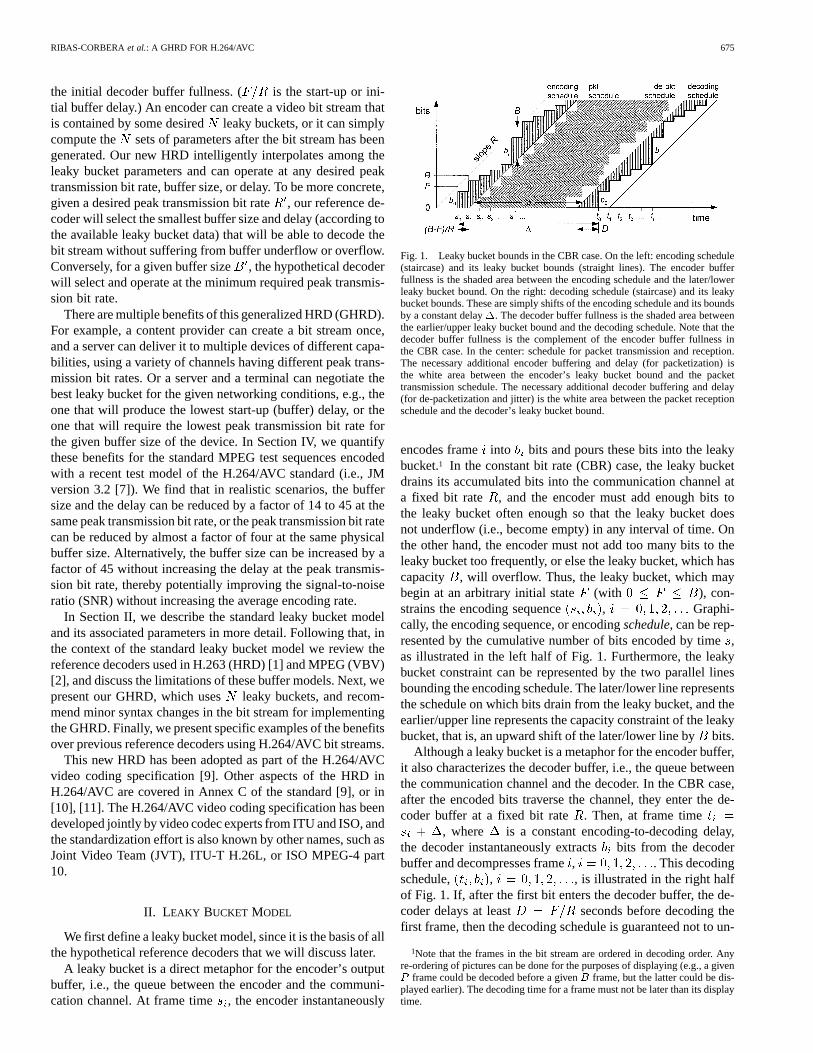
Fig. 1. Leaky bucket bounds in the CBR case. On the left: encoding schedule(staircase) and its leaky bucket bounds (straight lines). The encoder bufferfullness is the shaded area between the encoding schedule and the later/lowerleaky bucket bound. On the right: decoding schedule (staircase) and its leakybucket bounds. These are simply shifts of the encoding schedule and its boundsby a constant delay�. The decoder buffer fullness is the shaded area betweenthe earlier/upper leaky bucket bound and the decoding schedule. Note that thedecoder buffer fullness is the complement of the encoder buffer fullness inthe CBR case. In the center: schedule for packet transmission and reception.The necessary additional encoder buffering and delay (for packetization) isthe white area between the encoder’s leaky bucket bound and the packettransmission schedule. The necessary additional decoder buffering and delay(for de-packetization and jitter) is the white area between the packet receptionschedule and the decoder’s leaky bucket bound.
encodes frame into bits and pours these bits into the leakybucket.1 In the constant bit rate (CBR) case, the leaky bucketdrains its accumulated bits into the communication channel ata fixed bit rate , and the encoder must add enough bits tothe leaky bucket often enough so that the leaky bucket doesnot underflow (i.e., become empty) in any interval of time. Onthe other hand, the encoder must not add too many bits to theleaky bucket too frequently, or else the leaky bucket, which hascapacity , will overflow. Thus, the leaky bucket, which maybegin at an arbitrary initial state (with ), con-strains the encoding sequence , Graphi-cally, the encoding sequence, or encodingschedule, can be rep-resented by the cumulative number of bits encoded by time,as illustrated in the left half of Fig. 1. Furthermore, the leakybucket constraint can be represented by the two parallel linesbounding the encoding schedule. The later/lower line representsthe schedule on which bits drain from the leaky bucket, and theearlier/upper line represents the capacity constraint of the leakybucket, that is, an upward shift of the later/lower line bybits.
Although a leaky bucket is a metaphor for the encoder buffer,it also characterizes the decoder buffer, i.e., the queue betweenthe communication channel and the decoder. In the CBR case,after the encoded bits traverse the channel, they enter the de-coder buffer at a fixed bit rate . Then, at frame time
, where is a constant encoding-to-decoding delay,the decoder instantaneously extractsbits from the decoderbuffer and decompresses frame, . This decodingschedule, , , is illustrated in the right halfof Fig. 1. If, after the first bit enters the decoder buffer, the de-coder delays at least seconds before decoding thefirst frame, then the decoding schedule is guaranteed not to un-
1Note that the frames in the bit stream are ordered in decoding order. Anyre-ordering of pictures can be done for the purposes of displaying (e.g., a givenP frame could be decoded before a givenB frame, but the latter could be dis-played earlier). The decoding time for a frame must not be later than its displaytime.

676 IEEE TRANSACTIONS ON CIRCUITS AND SYSTEMS FOR VIDEO TECHNOLOGY, VOL. 13, NO. 7, JULY 2003
derflow the decoder buffer, due to the leaky bucket bounds in-herited from the parallel encoding schedule. Furthermore, withdelay , if the capacity of the decoder buffer is at least
, then the decoding schedule is guaranteed not to overflow thedecoder buffer, again due to the leaky bucket bounds inheritedfrom the parallel encoding schedule. In fact, observe that thefullnesses of the encoder and decoder buffers are complementsof each other in the CBR case [8]. Thus, the leaky bucket modeldetermines both the minimum decoder buffer size and the min-imum decoder buffer delay using three parameters,, , and
, by succinctly summarizing with upper and lower bounds theencoded sequence , .
The leaky bucket model can also be used with variable bit rate(VBR) channels, such as packet networks. If the VBR channelhas a long-term average bit rate that equals the long-term av-erage bit rate of the encoded sequence, then it is often convenientto continue to use the above CBR leaky bucket bounds. At thedecoder, the buffering and the delay due to the leaky bucketcan be augmented by additional buffering and delay to accom-modate both de-packetization and packet network delivery jitter.Likewise, at the encoder, the buffering and delay can be aug-mented by additional buffering and delay to accommodate pack-etization. The additional buffering and delay at both the en-coder and decoder are illustrated in Fig. 1. The resulting totalamount of buffering and delay are sufficient to guarantee con-tinuous media playback without stalling due to decoder bufferunderflow and without loss due to decoder buffer overflow. Inessence, at the decoder, the leaky bucket provides a deadline bywhich packets must be available for decoding, or risk being late.Similarly, at the encoder, the leaky bucket provides a deadlineby which the encoded bits will be available for packetization.
For VBR channels that have asustainablepeak bit rategreater than the long-term average bit rateof the encodedsequence, then it is beneficial to characterize the encoded se-quence using a leaky bucket with the higher leak rate
, yet allowing the leaky bucket to underflow (become empty)when the channel drains the bucket faster than the encoder canfill it. To illustrate, Fig. 2 shows thesameencoding and de-coding schedules as in Fig. 1, using a leaky bucket with thehigher leak rate . As in Fig. 1, the later/lower bound on theencoding schedule is the schedule by which bits drain from theleaky bucket and are transmitted or packetized. In Fig. 2, how-ever, flat spots in this transmission schedule indicate intervals inwhich the bucket is empty because there is nothing to transmit.The earlier/upper bound on the encoding schedule representsthe capacity constraint of the leaky bucket: an upward shift ofthe transmission schedule by bits. Since the bucket drainsat a rate greater than , the bucket can have a capacitysmaller than , while still not overflowing, and/or can start withan initial state smaller than . The transmitted bits enter thedecoder buffer after a constant transmission delay. If, after thefirst bit enters the decoder buffer, the decoder delays at least
seconds before decoding the first frame, then thedecoding schedule is guaranteed not to underflow the decoderbuffer. Furthermore, with delay , if the capacity ofthe decoder buffer is at least , then the decoding schedule isguaranteed not to overflow the decoder buffer. In this VBR case,the encoder buffer fullness and the decoder buffer fullness are
Fig. 2. Leaky bucket bounds in the VBR case. The encoding and decodingschedules are the same as in the CBR case in Fig. 1 (thus they have the sameaverage bit rate), but the peak transmission bit rateR is higher, resultingin a lower buffer sizeB , a lower initial delayD = F =R , and a lowerencoding-to-decoding delay� . On the left: the encoding schedule is boundedbelow/right by the schedule by which bits leave the encoder bucket and arenominally transmitted. Flat spots indicate intervals in which the bucket isempty because there is nothing to transmit. The encoding schedule is boundedabove/left by an upward shift of the transmission schedule byB bits. This isthe constraint imposed on the encoding schedule by the leaky bucket capacity.On the right: the decoding schedule is bounded above/left and below/right byrightward shifts of the transmission schedule. The earlier of these shifts is theschedule at which bits nominally arrive in the decoder buffer. Note that theencoder and decoder buffer fullnesses are no longer complementary. However,the decoder buffer fullness is bounded by the complement of the encoder bufferfullness (dotted).
no longer complementary. However, the complement of the en-coder buffer fullness provides a tight (achievable) upper boundto the decoder buffer fullness. The advantage of using a leakybucket with a peak rate greater than the average rate is that itallows a smaller decoder buffer size and delay for the same en-coded sequence.
Clearly, a VBR channel is a generalization of a CBR channel,and in either case a single leaky bucket is specifiable by threeparameters , where:
• is the peak transmission bit rate (in bits per second)at which bits may leave the encoder buffer and enter thedecoder buffer after a constant delay;
• is the capacity (in bits) of the encoder or decoder buffer;• is the initial decoder buffer fullness (in bits) before the
decoder can start removing bits from its buffer.2 anddetermine the initial or start-up delay, whereseconds.
A leaky bucket with parameters is said tocontainanencoded bit stream if there is no overflow of the encoder buffer(i.e., the leaky bucket) or equivalently, if there is no underflowof the decoder buffer. Thus, a leaky bucket that contains an en-coded bit stream provides constraints on the stream’s encodingand decoding schedules so that the resources necessary to de-code it are predictable.
A leaky bucket characterization of an encoded bit stream isespecially important when the bit stream is encoded off line (forapplications such as playback from a local disk, or streamingvideo on demand over a packet network from a remote server).When an entire bit stream is recorded and encoded before play-back, it is essential that the decoder buffer and delay require-
2A leaky bucket can also be specified by parameters(R;B; F ), whereFis the initial encoder buffer fullness. In this paper, we have chosen to use theinitial decoder buffer fullnessF = F , unless otherwise indicated. They arerelated byF + F = B.

RIBAS-CORBERAet al.: A GHRD FOR H.264/AVC 677
ments be stored along with the encoded bit stream, so that itwill be possible for a decoder to know whether it will be ableto decode a bit stream and what start-up delay to give it. Theleaky bucket model provides a way to parameterize these re-quirements.
When the bit stream is encoded online, that is, when the en-coder is connected directly to the transmission channel (for ap-plications such as point-to-point video telephony), then in somecircumstances, e.g., communication over a variable rate packetnetwork with very low jitter, the encoder can control or at leastknow the instantaneous bit rate at which bits arrive at thereceiver. In this case, rather than use a leaky bucket model, itmay be better to use a low-delay mode, in which the receivermay decode each frame of data as soon as it is fully received.In such a mode, the decoder buffer underflow is impossible (bydefinition) and decoder buffer overflow can be prevented by theencoder either by reducing to match the number of bits perframe, or by increasing the number of bits per frame to match
. Unfortunately, low-delay mode does not preserve presen-tation timing; constant end-to-end delay is sacrificed. Thus, theleaky bucket model is also important for on-line applicationswhen precise presentation timing is important (e.g., for broad-casting high quality video live), or when the encoder cannot con-trol or know the instantaneous rate at which bits arrive atthe receiver, or when is anyway either a positive constantor zero (e.g., for transmission in a multiplex over an isochronouschannel).
In this paper, we focus on generalizing the above singleleaky bucket model to multiple leaky buckets for H.264/AVC.As mentioned earlier, other aspects of the HRD in H.264/AVC,such as low-delay mode, are not addressed here, but areexplained in [9]–[11].
Before exploring multiple leaky buckets, let us be more spe-cific about how a single leaky bucket with parametersworks in H.264/AVC. As indicated above, let be theencoder schedule and let be the corresponding decoderschedule. The leaky bucket starts with initial fullness, whichmeans that if frame 0 is inserted into the leaky bucket at time
, then transmission of the initial bit of frame 0 begins (after adelay of ) at time
Transmission of the final bit of frame 0, indeed the final bit ofany frame for , ends at time
Hence, transmission of the initial bit of the subsequent framebegins at time
that is, when frame is inserted into the leaky bucket orwhen frame completes transmission, whichever is later. Now,
assuming a constant transmission delay, the initial bit of frame0 begins its arrival in the decoder buffer at time
Similarly, the final bit of frame 0, or indeed the final bit of anyframe for , ends its arrival in the decoder buffer at time
The initial bit of the subsequent frame will begin its arrival inthe decoder buffer at time
which follows since for all .The last three displayed equations form the basis of the HRDmodel in H.264/AVC. (In the specification, is known asthe and is known as the
.) The decoder bufferwill not underflow if and only if for all , frame arrives in thedecoder buffer before it is due for removal, that is,
This will be true if for all , which will in turnbe true if (which in turn will be true if theencoder buffer does not overflow). Hence, the decoder buffercapacity is usually set equal to the encoderbuffer (leaky bucket) capacity in order to minimizeboth the decoder delay and the decoder buffer size .For this reason, we do not ordinarily distinguish betweenand and we set .
Evolution of the encoder and decoder buffers can also be de-scribed in terms of buffer fullness. If the encoder buffer (theleaky bucket) starts with initial fullness , then when frame 0is inserted into the encoder buffer, the fullness of the encoderbuffer rises to
Thereafter, the fullness of the encoder buffer after insertingframe , is
(1.0)
The encoder buffer will not overflow if and only iffor all . The complement of these equations describes anupper bound on the decoder buffer fullness after removing frame
for . If the decoder waits until the decoder buffer fullnessreaches before removing and decoding the frame 0, then thefullness of the decoder buffer falls to
Thereafter, the upper bound on the fullness of the decoder bufferafter removing frame, , can be expressed as
(1.1)

678 IEEE TRANSACTIONS ON CIRCUITS AND SYSTEMS FOR VIDEO TECHNOLOGY, VOL. 13, NO. 7, JULY 2003
Fig. 3. Decoder buffer fullness when decoding a generic video bit stream thatis contained in a leaky bucket having parameters(R;B; F ). R is the peakincoming (or channel) bit rate in bits per second,B is the buffer size in bits,andF is the initial decoder buffer fullness in bits.D = F=R is the initial orstart-up (buffer) delay in seconds. The number of bits for theith frame isb .The coded video frames are removed from the buffer (typically according to thevideo frame rate), as shown by the drops in buffer fullness.
It is simple to prove by induction that for all ;that is, (1.0) and (1.1) are complements. That the complementof the encoder buffer fullness is indeed an upper bound on thefullness of the decoder buffer can be seen from the fact thatin any time interval of length , at most bits can enterthe decoder buffer. Hence, as illustrated in Fig. 2, a leftwardshift by of the later/lower bound on the decoding schedulemust lie below its upward shift by . In other words, the actualdecoder buffer fullness is bounded above by the complementof the encoder buffer fullness. Furthermore, the bound is tight,for if the encoder ever fills up the leaky bucket then the actualdecoder buffer fullness achieves the bound. Thus, if a decoderbuffer size is minimally sufficient to contain the upperbound on the decoder buffer fullness, then it is also minimallysufficient to contain the actual decoder buffer fullness. Hence,in the remainder of the paper, we safely use (1.1) as a surrogatefor the actual decoder buffer fullness, and refer to it simply asthe “decoder buffer fullness.” Since this is now complementaryto the encoder buffer fullness, we are able to focus exclusivelyon the decoder buffer fullness, and we drop the superscript “”from our notation. Fig. 3 illustrates the decoder buffer fullnessas a function of time for a bit stream that is contained in a leakybucket having parameters .
We now make the following observation. A given videostream can be contained in many leaky buckets. For example, ifa video stream is contained in a leaky bucket with parameters
, it will also be contained in a leaky bucket with alarger buffer , , or in a leaky bucket witha higher peak transmission bit rate , , or ina leaky bucket with larger start-up delay , ,
. Moreover, it can also be contained in a leaky bucketwith a lower peak transmission bit rate , , ifthe video is time-limited. In the worst case, asapproaches 0,the buffer size and initial buffer fullness will need to be as largeas the bit stream itself. Put another way, a video bit stream canbe transmitted at any peak transmission bit rate (regardless ofthe average bit rate of the clip) as long as the buffer size anddelay are large enough.
Thus, for any value of the peak transmission bit rate, wecan find the minimum buffer size and the minimum initialbuffer fullness that will contain the bit stream. This can bedone by iterating (1.1), as illustrated by the Matlab code in Ap-pendix B. Surprisingly, both minima can be achieved simultane-
Fig. 4. Illustration of peak bit rateR and buffer sizeB values for agiven bit stream. This curve indicates that in order to transmit the stream at apeak bit rateR, the decoder needs to buffer at leastB (R) bits. Observe thathigher peak rates require smaller buffer sizes. Alternatively, if the size of thedecoder buffer is B, the minimum peak rate required for transmitting the bitstream is the associatedR (B).
ously, as we prove in Appendix A (Proposition 2), even thoughin general the buffer size required to contain the bit stream staysthe same or increases as the initial buffer fullness decreases.
By computing for each , we can plot a curve ofvalues such as the one in Fig. 4.3
A key observation is that the curve of pairs forany bit stream (such as the one in Fig. 4) is piecewise linear andconvex. Let us illustrate this interesting property using a simple,intuitive example. Consider the three plots of decoder bufferfullness in Fig. 5. These plots are generated when decoding avideo bit stream that contains five frames, whereare the number of bits per frame , respectively. Thepeak transmission bit rate is (top), (middle), and(bottom), and .
For clarity, the buffer (in each of the three cases) is initiallyfilled to the maximum value (which here represents the phys-ical buffer size), i.e., , although other initial values couldhave been selected as well. As expected, the minimum buffersize required to decode the bitstream decreases with larger peaktransmission bit rate, i.e., .One can easily show that
(2)
where is the time interval between frames, which in thisexample is assumed to be constant (i.e., the decoding framerate is frames/s). Observe that the formulas forand correspond to two different points on the same
3This curve is actually computed from a real video bit stream using (1.1) inthe Matlab program of Appendix B.

RIBAS-CORBERAet al.: A GHRD FOR H.264/AVC 679
Fig. 5. The plots illustrate the decoder buffer fullness when decoding a videobit stream transmitted at bit rateR (top),R (middle), andR (bottom), whereR < R < R . Observe that the minimum buffer size required to decode thebitstreams isB (R) > B (R ) > B (R ).
straight line of slope , and that the values of for all bitrates between and will lie on that line as well, because therespective decoder buffer plots would fall in between the topand middle plots in Fig. 5. For transmission bit rates slightlylarger than , the value of will still lie on that same line,but at some point, the buffer will fill up within some frameinterval (here between frames 1 and 2, as seen in the bottomplot of Fig. 5) and the formula for will change to that ofa straight line of slope . The value of derived in(2) falls on this second straight line. Fig. 6 illustrates the curveof values in this example.
Although this is a specific example, one can intuitively seethat the decoder buffer plot for any video bit stream (of anynumber of frames) can be analyzed using the same process. Asthe peak transmission bit rate increases, the value of willdecrease following straight line formulas of the same form asthose in (2), i.e., a summation of the number of bits forframesand a slope — . The next line in the sequence willhave fewer frames in the summation and hence a less negativeslope, and as a result a piecewise linear curve that is monoton-ically decreasing such as that in Fig. 6 can be plotted. Sinceeach new segment in the sequence has a less negative slope,such a piecewise linear curve is convex. For completeness, arigorous proof of the piecewise linear and convex properties ofthe curve of pairs (using induction) is provided in
Fig. 6. Illustration of(R ;B ) pairs for the bit stream used in the decoderbuffer plots of Fig. 5. As the channel rate increases,B decreases followinga piecewise linear curve. Observe thatB (R) andB (R ) lie on the samestraight line of slope�3� , while B (R ) lies on the line of slope�� , asindicated in (2).
Appendix A. Not surprisingly, such linear and convex proper-ties apply to as well, which is also shown in Ap-pendix A.
Because of the convexity, if points of the curve are pro-vided, the decoder can linearly interpolate the values to arrive atsome points that are slightly but safelylarger than . In this way, as we quantify inSection V, one is able to safely reduce the buffer size, and thedelay, by well over an order of magnitude, relative to a singleleaky bucket containing the bit stream at its average rate. Al-ternatively, for the same delay, one is able to reduce the peaktransmission rate by almost a factor of four, or possibly evenimprove the SNR.
III. PREVIOUS WORK
We next explain the hypothetical reference decoders inMPEG and H.263 in the context of leaky bucket models.
A. MPEG’s Video Buffering Verifier (VBV)
The VBV [2] can operate in two modes: CBR and VBR.MPEG-1 and MPEG-4 only support the CBR mode, whileMPEG-2 supports both modes.
The VBV operates in CBR mode when the bit stream is con-tained in a leaky bucket having parameters and thefollowing conditions hold:
• the average bit rate of the stream;• the value of is stored in the syntax parameter
vbv_buffer_size using a special size unit (i.e., 161024bit units);
• the value of is stored in the syntax element vbv_delayassociated to the first video frame in the sequence usinga special time unit (i.e., number of periods of a 90 KHzclock);
• the decoder buffer fullness follows the following equa-tions:
(3)
The encoder must ensure that is always greater than orequal to zero while is always less than or equal to. In otherwords, the encoder must ensure that the decoder buffer does notunderflow or overflow.

680 IEEE TRANSACTIONS ON CIRCUITS AND SYSTEMS FOR VIDEO TECHNOLOGY, VOL. 13, NO. 7, JULY 2003
The VBV operates in VBR mode when the bit stream is con-tained in a leaky bucket having parameters and thefollowing conditions hold:
• the peak or maximum rate. is higherthan the average rate of the bit stream;
• , i.e., the buffer fills up initially;• the value of is represented in the syntax parameter
vbv_buffer_size, as in the CBR case;• the value of is not stored and vbv_delay is set to FFFF
(in hex);• the decoder buffer fullness follows the following equa-
tions:
(4)
The encoder must ensure that is always greater than orequal to zero. That is, the encoder must ensure that the decoderbuffer does not underflow. However, in this VBR case, the en-coder does not need to ensure that the decoder buffer does notoverflow. If the decoder buffer becomes full, then it is assumedthat the encoder buffer is empty and hence no further bits aretransmitted from the encoder buffer to the decoder buffer.
The VBR mode is useful for devices that can read data up tothe peak rate . For example, a DVD includes VBR clipswhere is about 10 Mbps, which corresponds to the max-imum reading speed of the disk drive, even though usually theaverage rate of the DVD video stream is only about 4 to 6 Mbps.
Fig. 7 illustrates plots of decoder buffer fullness for some bitstreams operating in CBR and VBR mode, respectively.
There are some aspects of VBV that we do not address herebecause they are either not relevant with respect to this contri-bution, or are simply special cases of the leaky bucket model.For example, the VBV includes a low-delay mode that toleratesframe skipping.
B. H.263’s HRD
The HRD model for H.263 [1] (which is equivalent to that inH.261) operates in low-delay mode. It resembles the CBR modeof MPEG’s VBV, except for the following.
• The decoder inspects the buffer fullness at some time in-tervals and decodes a frame as soon as all the bits for theframe are available. This approach results in a couple ofbenefits: 1) the start-up delay is minimized becauseisusually just slightly larger than the number of bits for thefirst frame and 2) if frame skipping is common, the de-coder simply waits until the next available frame. As men-tioned above, the latter is enabled in the low-delay modeof MPEG’s VBV as well.
• The check for decoder buffer overflow is done after thebits for a frame are removed from the buffer (i.e.,
must be less than or equal to, for all). This relaxes the constraint for sending largeframes
once in a while, but there is a maximum value for thelargest frame.
(a)
(b)
Fig. 7. Examples of typical plots of decoder buffer fullness for (a) CBR and(b) VBR for MPEG-2’s VBV model.
• The transmission bit rate varies along time, and it is as-sumed that both encoder and decoder know the bit rate ateach time instant.
The HRD in H.263 is suitable for low-delay communications(e.g., video conferencing). Observe that in such HRD, the de-coding and display times vary significantly across frames, andhence this approach is not appropriate for constant-delay time-preserving applications.
C. Limitations of Previous Models
Observe that all previous hypothetical reference decoders op-erate at only one point of the curve in Fig. 4. As a result,these decoders have the following drawbacks.
• If the bit rate available in the channel is lower than(e.g., this is common for internet streaming and progres-sive download, or when an MPEG VBR clip needs to betransmitted at a rate lower than the peak), strictly speaking,the hypothetical decoder would not be able to decode thebit stream.
• In practice, a decoder will not know the size of thebuffer required for this lower rate, and generally itwill run into buffer problems while decoding the bitstream. The best that a smart decoder could do wouldbe to find a tight upper-bound for the buffer size. Onecan easily show that an almost tight4 upper bound is
, where is the time lengthor duration in seconds of the video sequence (to bemore specific, is the time difference between thedecoding times of the last and first frames in the
4A tight upper bound, which depends on the initial decoder buffer fullnessFof the original buffer, isB = (B � F )(R =R) + F + (R � R )T . This isbecause the initial buffer fullnessF of the new decoder buffer must be at leastF + (R � R )T to guarantee that the new decoder buffer will not underflowby timeT when it receives bits at rate onlyR < R, and because the headroomB � F must be at least(B � F )(R =R) to guarantee that the new decoderbuffer will not overflow by time(B � F )=R when it receives bits at rateR .

RIBAS-CORBERAet al.: A GHRD FOR H.264/AVC 681
coded bit stream). Clearly, this bound increases thebuffer size and delay requirements very rapidly andmay not be very useful in practice (especially ifislarge and is significantly lower than ).
• If the available bandwidth is larger than (e.g., thisis also common for internet streaming, as well as forlocal playback), the previous hypothetical decoders couldoperate in the VBR mode and decode the bit stream.However, as no additional information on the Rate-Buffercurve is available, the buffer size required to decode thebit stream cannot be reduced (as we will see later in theexamples).
• If the physical buffer size in a decoder device is smallerthan , the device will not be able to decode that bitstream.
• If the buffer size is larger than , the device will be ableto decode the bit stream but the start-up delay will be thesame.
• More generally, if a bit stream is generated according toa leaky bucket and no other leaky bucket pa-rameters are known, one will not usually be able to be dis-tribute such bit stream through different networks havingpeak transmission bit rates smaller than, and to a va-riety of devices with buffer sizes smaller than. Also, thestart-up delay will not be minimized.
IV. A GENERALIZED GHRD
We present a GHRD that can operate given the informationof leaky bucket models
(5)
each of which contains the bit stream. Without loss of generality,let us assume that these leaky buckets are ordered from smallestto largest bit rate, i.e., . Let us also assume thatthe encoder computes these leaky bucket models correctly, andhence .
The desired value of can be selected by the encoder. (If, the GHRD is essentially equivalent to the VBR mode
of MPEG’s VBV). The encoder can choose to:
1) pre-select the leaky bucket values and encode the bitstream with a rate control that makes sure that all of theleaky bucket constraints are met;
2) encode the bit stream and then use (1.1) to compute a setof leaky buckets containing the bit stream atdifferentvalues of ;
3) do both.
The first approach can be applied to live or on-demand trans-mission, while 2) and 3) only apply to on-demand.
The number of leaky buckets and the leaky bucket param-eters (5) are inserted into the bit stream. In this way, the decodercan determine which leaky bucket it wishes to use, knowing thepeak bit rate available to it and/or its physical buffer size. Theleaky bucket models in (5), as well as all the linearly interpolatedor extrapolated models, are available for use. Fig. 8 illustrates aset of leaky bucket models and their interpolated or extrapo-lated values.
Fig. 8. Example of(R;B) values available for the GHRD, all of which areguaranteed to contain the bit stream.T is the time length or duration of theencoded video sequence.
The interpolated buffer size between points andfollow the straight line
(6)
Likewise, the initial decoder buffer fullness can be linearlyinterpolated
(7)
The resulting leaky bucket with parameters is guar-anteed to contain the bit stream, because, as we prove in Propo-sition 1 of Appendix A, the minimum buffer size is convexin both and , that is, the minimum buffer size corre-sponding to any convex combination
, , is less than or equal to.
As discussed earlier, observe that ifis larger than , theleaky bucket will also contain the bit stream, andhence and are the buffer size and initial decoder bufferfullness recommended when . If is smaller than ,then the upper bound can be used (andone can set ), where is the time length of the videosequence in seconds. These values outside the range ofthe points are also shown in Fig. 8.
The number of bits required for the leaky bucket parametersis minimal. If , , and were encoded in the same units as
, vbv_buffer_size, and vbv_buffer_delay (in the MPEG-2bit stream syntax), then the number of bits required for theseelements would be 30, 18, and 16, respectively, for a total of 64bits per leaky bucket. The number of leaky bucketscouldbe specified with 8 bits. This information would be succinctenough that it could be re-specified at any point in the bitstream,such as at all random access points.
In the H.264/AVC specification, the number of leaky bucketsis specified with a variable-length code in the range 1 to 32.Each bit rate in bits per second is specified with a variable-lengthmantissa in the range 1 to 2 and a fixed-length base-2 ex-ponent in the range 6 to 21. Each buffer size in bits is specified

682 IEEE TRANSACTIONS ON CIRCUITS AND SYSTEMS FOR VIDEO TECHNOLOGY, VOL. 13, NO. 7, JULY 2003
with a variable-length mantissa in the range 1 to and afixed-length base-2 exponent in the range 4 to 19. All of theseare in the HRD Parameters section of the video usability infor-mation (VUI). The initial decoder buffer delay in 90-kHz ticksis specified in the Buffering Period section of the supplementalenhancement information with a fixed-length code. The numberof bits in this code is specified in the HRD parameters sectionof the VUI by a fixed-length code in the range 1 to 32.
V. EXPERIMENTAL RESULTS: EVALUATION OF THE GHRD
To evaluate the benefits of the GHRD, we encoded a 130-svideo clip (which contained a sequence of 13 MPEG clips com-bined, i.e., “Stefan”, “Akiyo”, “Mother and Daughter”, “FunFair”, “Foreman”, “Bream”, “News”, “Sean”, “Children”, “Mo-bile & Calendar”, “Weather”, “Container”, and “Hall”) with theTest Model JM version 3.2 [7] with the default parameters (i.e.,five reference frames, 1/8th motion accuracy, arithmetic codingON, hadamard transformON, error robustnessOFF, B framesOFF, andRD optimizationON, and a motion search range of 16pixels). We set and used the formula (1.1) to providethe plot in Fig. 9. To be more concrete, we ranthe simple Matlab program in Appendix B which makes use of(1.1).
The bit stream in Fig. 9 was produced with andyielded an average bit rate of 600 kbits/s. As shown in the figure,at a constant transmission bit rate of 600 kbits/s, the decoderneeds a buffer size of about 16 500 kbits. With an initial decoderbuffer fullness equal to 16 500 kbits, the start-up delay is about27 s. Thus, this VBR encoding (produced with no rate control)shifts bits by up to 27 s in order to achieve constant quality overits encoded length.
The figure also shows that at a peak transmission bit rate of2400 kbits/s (e.g., the video bit-rate portion of a 2CD), thedecoder needs a buffer size of only 370 kbits, sufficiently smallfor a consumer hardware device. With an initial buffer fullnessequal to 370 kbits, the start-up delay is only about 0.15 s.
Thus, for this encoding, two leaky bucket models might typ-ically be useful.
1) ( , , ).This leaky bucket permits transmission of the video over aCBR channel, with a delay of about 27 s. While this delaymay be too large for many scenarios, it is probably ac-ceptable for streaming or progressive download of moviesover the Internet, for example.
2) ( , , ).This leaky bucket permits transmission of the video overa shared network with peak rate 2400 kbits/s, or permitslocal playback from a 2 CD, with a delay of about 0.15s. This subsecond delay is acceptable for random accessplayback with VCR-like functionality.
If only the first leaky bucket is specified in the bit stream,but not the second, then even when playing back over achannel with peak bit-rate 2400 kbits/s, the decoder woulduse a buffer of size 16 500 kbits and thus the delay wouldbe . This is toolarge for random access playback with VCR-like functionality.However, if the second leaky bucket is specified as well, then
Fig. 9. Plot of leaky bucket parameters(R;B) for an H.264/AVC compressedvideo clip with QP = 26. The points labeled with “�” correspond to theminimum buffer sizeB needed to contain a bit stream with the associatedrateR . These points were computed from the bit stream using the Matlabprogram in Appendix B, which uses the formulae in (1.1) and scans bit ratesfrom 50 kbits/s to 3 Mbps in increments of 50 kbits/s. The other points betweenthe “�” are linearly interpolated. Observe that, in practice, only a small subsetof points (e.g., 4 or 5) may characterize the curve fairly well.
at peak bit-rate 2400 kbits/s the buffer size drops to 370 kbitsand the delay drops to 0.15 s, as we have seen.
On the other hand, if only the second leaky bucket is speci-fied, but not the first, then at a constant transmission rate of 600kbits/s, even a smart decoder would be forced to use a bufferthat is far larger than necessary, to ensure that the buffer will notoverflow:
. This corresponds to aninitial delay of 391 s, or about 6.5 min, over three times thelength of the original clip, which is far from acceptable. How-ever, if the first leaky bucket is specified as well, then at rate 600kbits/s the buffer size drops to 16 500 kbits and the delay dropsto 27 s, as we have seen.
Moreover, if both leaky buckets are specified, then thedecoder can linearly interpolate between them [using (6) and(7)], for any bit rate between 600 and 2400 kbits/s, therebyachieving near-minimal buffer size and delay at that rate.Extrapolation is also more efficient both below 600 kbits/sand above 2400 kbits/s, compared to extrapolation with only asingle leaky bucket anywhere between 600 and 2400 kbits/s.
As the above example shows, even just two leaky bucketscan provide well over an order of magnitude reduction in buffersize (e.g., a factor of 234 370 kbits/16 500 kbits14 in onecase and 16 500 kbits/370 kbits45 in another), and a corre-sponding reduction in delay (e.g., 391 s/27 s14 s in one caseand 6.9 s/0.15 s 45 s in another) at a given peak transmissionbit rate.
Conversely, it is also possible to reduce the peak transmissionbit rate for a given decoder buffer size. Indeed, as is clear fromFig. 9, if the curve can be obtained by interpolating and/orextrapolating multiple leaky buckets, then it is possible for adecoder with a fixed physical buffer to choose the minimumpeak transmission bit rate needed to safely decode the bit stream

RIBAS-CORBERAet al.: A GHRD FOR H.264/AVC 683
without decoder buffer overflow. For example, we know fromthe figure that if the decoder has a fixed buffer of size 16 500kbits, then the peak transmission bit rate for the encoding can beas low as 600 kbits/s. However, if only the second leaky bucketis specified, but not the first, then the decoder can reduce the bitrate to no less than
. In this case,compared to using a single leaky bucket, using just two leakybuckets reduces the peak transmission rate by almost a factor offour, for the same decoder buffer size.
It is quite likely that having multiple leaky buckets can alsoimprove the quality of the reconstructed video,at the same av-erageencoding rate, in the following sense. Suppose both leakybuckets are available for the encoding described above. Then,as we have seen, it is possible to play back the encoding with adelay of 27 s if the peak transmission rate is 600 kbits/s, andwith a delay of 0.15 s if the peak transmission rate is 2400kbits/s. However, if the second leaky bucket is unavailable, thenthe delay increases from 0.15 to 6.9 s at 2400 kbits/s. To re-duce the delay back to 0.15 s without the benefit of the secondleaky bucket, it would suffice to re-encode the clipwith ratecontrol by reducing the buffer size (of the first leaky bucket)from 16 500 kbits to , afactor of 45. This would ensure that the delay is only 0.15 s if thepeak transmission rate is 2400 kbits/s. However, the quality ofthis rate-controlled stream would vary over time, and it is quitelikely that the average quality (SNR) would be lower than thatof the original constant-quality stream at the same average bitrate. Unfortunately we cannot yet evaluate this decrease in SNRwith objective tests, because as of this writing there is no ratecontrol in the test model of H.264/AVC. Thus we can only con-jecture that specifying a second leaky bucket can increase theSNR with no change in the average bit rate (except for the ad-ditional bits per clip to specify the second leaky bucket). Thisincrease in SNR would be visible on playback for every peaktransmission rate.
The benefits of specifying multiple leaky buckets in a gen-eralized hypothetical reference decoder appear, of course, onlyin heterogeneous situations, where a single encoding is trans-mitted over channels with different peak bit rates, or to deviceswith different physical buffer sizes. However, this is increas-ingly the case. Content that is encoded offline and stored on adisk is often played back locally as well as streamed over net-works with different peak rates. Even for local playback, dif-ferent drives speeds (e.g., 1CD through 8 DVD and be-yond) affect the peak transfer rate. And of course the peak trans-mission bit rates through network connections also vary dramat-ically according to the speed of the limiting link, which is typi-cally near the end user (e.g., 100 or 10 baseT Ethernet, T1, DSL,ISDN, modems, etc.). Buffer capacities of playback devices alsovary significantly, from desktop computers with gigabytes ofbuffer space to small consumer electronic devices with bufferspace that is smaller by several orders of magnitude. Typically,content providers spend a significant amount of effort creating asingle bit stream (e.g., top studios may spend over 80 h to createa DVD), and they wish to reach the largest audience, with thebest user experience. The multiple leaky buckets in the proposedgeneralized hypothetical reference decoder make it possible for
Fig. 10. Same plot as Fig. 9 but whenQP = 38. Once again, observe thatonly a subset of these points (e.g., 4 or 5) already characterize this curve well.In this case, the average bit rate of the clip is 150 kbits/s and the related buffersize and delay are 3500 kbits and 23 s, respectively. If the clip were streamed ina LAN or DSL channel with higher bit rate, say 500 kbits/s, our new approachwould reduce the buffer size requirement to only 116 kbits, and the new start-updelay would be only 0.23 s.
the same bit stream to be transmitted over a variety of chan-nels with the minimum startup delay, minimum decoder bufferrequirements, and maximum possible quality. This applies notonly to video that is encoded off-line, but also to live video thatis broadcast simultaneously through different channels to dif-ferent devices. In short, the proposed GHRD adds significantflexibility to the transmission of existing bit streams.
On the other hand, it must be remembered that although dif-ferent leaky buckets may describe transmission of an encodedbit stream at different peak transmission bit rates, the differentleaky buckets do not alter the average bit rate of the encodedbit stream. Thus, although the different leaky buckets for an en-coded bit stream may help the decoder to choose the minimalbuffer size and startup-delay to play back the stream flawlesslyunder the prevailing network conditions, once the stream beginsto play, the stream’s multiple leaky buckets do nothing to adaptthe stream’s encoded bit rate to fluctuating network conditions.However, the leaky bucket bounds can be used by the decoderto decide, for example, whether its buffer is in danger of under-flowing or overflowing under the prevailing network conditions.If so, then the decoder can switch to a new stream with a dif-ferent average bit rate, and a whole new set of associated leakybuckets. As with any stream switch (e.g., after a seek), the newset of leaky buckets can be used to bound the decoding scheduleof the new stream, to ensure that the decoder buffer will not un-derflow or overflow after the stream switch, given the desiredstart-up delay.
Fig. 10 shows a further example of an H.264/AVC clip com-puted with a higher QP. Some of the benefits of the proposedapproach in this case are quantified in the caption of the figure.
VI. CONCLUSIONS
We have presented a hypothetical reference decoder which isa generalization of those in prior standards. This new GHRD re-

684 IEEE TRANSACTIONS ON CIRCUITS AND SYSTEMS FOR VIDEO TECHNOLOGY, VOL. 13, NO. 7, JULY 2003
Fig. 11. Decoder buffer state as a function of time.
quires only a few syntax elements at random access points of thebit stream, and provides much higher flexibility for bit streamdelivery through today’s emerging networks where bandwidthis variable and terminals have a variety of bit rate and bufferingcapabilities. This new reference decoder enables these new sce-narios, while reducing the transmission delay to a minimum forthe available bandwidth. In addition, it minimizes the channelbit-rate requirement for delivery to devices with given physicalbuffer size limitations. In our tests using H.264/AVC video bitstreams, we found that the buffer size and the start-up delayfor some terminals can be reduced by a factor of 14 to 45, orthe peak transmission bit-rate requirement can be reduced byalmost a factor of four. The GHRD is applicable to any multi-media (e.g., video, audio) data compression and communicationsystem. It has recently been adopted as part of the H.264/AVCvideo codec standard specification.
APPENDIX I
A. Proof That the Curve is Decreasing andConvex
In this Appendix, we prove that both the minimum decoderbuffer size and the minimum decoder buffer delayare decreasing, convex functions of the bit rate. Therefore,knowing the values of one of these functions at several bit rates,say , allows the decoder to linearlyinterpolate the values to arrive at a value that isslightly but safely larger than .
Our first goal is to derive expressions for and asfunctions of the bit rate and an initial buffer state. Fig. 11illustrates the decoder buffer state as a function of time, whereis the size of the decoder buffer in bits,is the rate at which bitsarrive into the decoder buffer in bits per second, andis thenumber of bits that the decoder accumulates before extractingand decoding the first frame. Define , and let
, , denote the number of bits codedfor frame at time (relative to ), where is the numberof frames in the sequence. Then the number of bitsin thedecoder buffer immediatelyafter frame is extracted can beexpressed recursively as
This can be made nonnegative for all (forfixed and ) by making sufficiently large. is thesmallest such sufficiently large. That is, for any fixed
The decoder buffer delay is . Hence,for fixed and , the minimum decoder buffer delay is
To show that these are convex inand (and various otherproperties), it simplifies matters slightly to consider the state oftheencoderbuffer as a function of time. The encoder buffer canbe considered as a leaky bucket of sizebits that leaks bits at aconstant rate bits per second into the channel (and from there,after a fixed delay, into the decoder buffer). The encoder inserts
bits into the bucket at each time corresponding to frame. The bucket may drain completely before another frame is in-
serted, in which case no bits are transmitted while the bucketis empty. The bucket begins with initial fullness bits. Theseinitial “dummy” bits are not transmitted. However, they re-strict the size of the first few framesto at most
bits, thereby serving to limit the decoding delay. (Ina constant bit-rate system, in which the encoder buffer is notallowed to underflow, the initial “dummy” bits would alsoserve to delay transmission of the first real encoded bits, therebypreventing buffer underflow. In a VBR system, this would not benecessary (see Figs. 1 and 2.) If the bucket sizeis sufficientlylarge, then the number of bits in the bucket immediately afterframe is inserted can be expressed recursively as
Note that this expression does not depend on the bucket size.Lemma 1: For all , . That is, and are
complementary.Proof: By induction, using the formulas for and :
Clearly, . For , assume .Then it is not difficult to see that .
Lemma 2: . That is, is the maximumnumber of bits in the leaky bucket.
Proof: Using Lemma 1,.
Lemma 3: is monotonically nonincreasingas a func-tion of , for fixed .
Proof: Let . We show thatby first showing that for each , then in-voking Lemma 2. By induction: Clearly, . For
, assuming , it is easy to see that, hence
the conclusion follows.Lemma 4: is continuousas a function of , for fixed.
Proof: By induction, is continuous in , for each. Apply Lemma 2.
Lemma 5: is piecewise linearas a function of , forfixed .
Proof: By induction, is piecewise linear in , foreach . Apply Lemma 2.
Lemma 6: is convexas a function of , for fixed .Proof: By induction, is convex in , for each .
Apply Lemma 2.The following lemmas are similarly proved.

RIBAS-CORBERAet al.: A GHRD FOR H.264/AVC 685
Lemma 7: is monotonically nondecreasingas a func-tion of , for fixed .
Lemma 8: is continuousas a function of , for fixed.Lemma 9: is piecewise linearas a function of , for
fixed .Lemma 10: is convexas a function of , for fixed .A fortiori, the following can be similarly proved.Proposition 1: is convexas a bi-variate function of
and .As a bi-variate function of and , denote
.Definition 1: . This is the
minimum possible buffer size given.Definition 2: . This is the
initial decoder buffer fullness given and .Definition 3: . This is the
minimum possible initial decoder buffer fullness given.Definition 4: . This is the
corresponding initial encoder buffer fullness.Lemma 11: For some ,
forfor
That is, for fixed , is a constant as a function ofuntil reaches a breakpoint , after which pointincreases as a constant plus.
Proof: By Lemma 7, . Fur-thermore, by Lemmas 7, 9, and 10, the (right) derivative
is nonnegative and is stepwise increasing. Hence,it suffices to show that must equal either 0 or 1. Inturn, by Lemma 2, it suffices to show that for all, the (right)derivative must equal either 0 or 1. Let bethe first index for which . Then byinduction, for , andotherwise.
Lemma 12: For some ,
forfor
That is, for fixed , decreases as a constant minusuntil reaches a breakpoint , after which point isconstant.
Proof: Follows from Lemma 11 and Definition 2.Proposition 2: For any , and are simul-
taneously achieved by , and this is theonly value of at which both minima are achieved.
Proof: Follows from Lemmas 11 and 12 and Definition 4.We now turn our attention to .Lemma 13: ismonotonically decreasingas a function
of , for fixed .Proof: For fixed , the numerator is monotonically non-
increasing (by Lemma 3), while the denominator is strictly in-creasing.
Lemma 14: is continuousas a function of , for fixed.
Proof: Follows from the continuity of (Lemma 4).
Lemma 15: is convexas a function of , for fixed .Proof: Except at the finite number of points where
does not exist,, by the chain rule. Both terms are negative
and increase monotonically to zero, by Lemmas 3 and 6.The following are corollaries of Lemma 12.Lemma 16: is monotonically nonincreasing as a
function of , for fixed .Lemma 17: iscontinuousas a function of , for fixed.Lemma 18: is piecewise linearas a function of ,
for fixed .Lemma 19: is convexas a function of , for fixed .
APPENDIX II
A. Matlab Program for Computing the Curvefor a Bit Stream
clear all;
clf;
% bits(i) is number of bits per frame i.
% Frame rate in frames=s of the given stream.
FrameRate = 30;
% Number of frames.
N = max (size(bits)).
% Calculate data for R� B plot
j = 0;
% Test bit rates from 50 kbps=s to 3 Mbps.
% Assume an initial (dummy) buffer sizeB = R�20:.
% buff1 is buffer state before frame removal.
% buff2 is buffer state after frame removal.
% Assume that initially buffer is full :
% F = buff1(1) = B.
for R = 50000 : 50000 : 3000000
j = j + 1;;
B = R�20;;
buff1 = zeros(1; N+ 1);
buff1 = zeros(1; N);
buff1(1) = B;;
minbuff = buff1(1);
for i = 1:1:N,
buff2(i) = buff1(i)� bits(i);
if (buff2(i) < minbuff)minbuff = buff2(i);
end
buff1(i + 1) = buff2(i) + R=FrameRate;
if (buff1(i + 1) > B) buff1(i + 1) = B;
end
end
% Minimum buffer size in bits:
Bmin = B� minbuff;
% Peak bit rate in kbps.
X(j) = R=1000;
% Minimum buffer size in kbits:
Y(j) = (Bmin)=1000;
% Simulate leaky bucket to find Fmin.
% Set buffer size to be its minimum value.

686 IEEE TRANSACTIONS ON CIRCUITS AND SYSTEMS FOR VIDEO TECHNOLOGY, VOL. 13, NO. 7, JULY 2003
% Initially assume Fmin is zero.
% Whenever underflow occurs do (1) and (2).
% (1) increase Fmin by underflow amount.
% (2) reset buffer.
B = Bmin;
Fmin = 0;
Buff1(1) = Fmin;
for i = 1:1:N
buff2(i) = buff1(i) � bits(i);
if (buff2(i) < 0)
Fmin = Fmin + (0� buff2(i))
buff2(i) = 0;
end
buff1(i + 1) = buff2(i) + R=FrameRate;
if (buff1(i+ 1) > B) buff1(i + 1) = B;
End of loop for R
end
holdoff;
plot(X; Y;' � �' );
ylabel(' Bmin (kbits)' )
xlabel(' Rmin (kbits=s)' );
hold
axis([0 max(X) 0 max(Y)]);
Explanation of the Matlab program follows.
• We initially set the buffer size to any arbitrary value (inthis case the bit rate times 20 s, but we could have chosenany other value).
• We then compute the value of buffer fullness along timeusing (1.1).
• Next, we determine the smallest buffer size needed to con-tain the bit stream “ ”, where min-buff is the minimum value of buffer fullness. Observe thatminbuff could be negative, which simply says that theoriginal arbitrary buffer size was too small to contain thebit stream, i.e., .
• Finally, we compute the minimum initial buffer fullness. We start setting to 0 and increase it as much
as needed to prevent decoder buffer underflow. willtake the smallest value in for which underflowdoes not occur
Observe that one could use a very small rate increment in theprogram above, compute the derivatives of thecurve at each point, and then determine the critical points atwhich the derivative does not exist (i.e.,the points where thesegments of the piece-wise lines of different slopes join).
ACKNOWLEDGMENT
The authors would like to thank the anonymous reviewersfor their valuable suggestions. They are also grateful to Dr. G.Sullivan for providing many insightful comments and revisions.
REFERENCES
[1] “Annex B, hypothetical reference decoder,” in Video Coding for LowBit Rate Communication, ITU-T Recommendation H.263, Jan. 1998.
[2] “Annex C, video buffering verifier,” in Information Tech-nology—Generic Coding of Moving Pictures and Associated AudioInformation: Video (MPEG-2/H.262), 2000, ISO/IEC 138 180-2.
[3] J. Crowcroft, M. Handley, and I. Wakeman,Internetworking Multi-media. San Mateo, CA: Morgan Kaufmann, 1999.
[4] J. Keyes,Webcasting. New York: McGraw-Hill, 1997.[5] C.-Y. Hsu, A. Ortega, and A. R. Reibman, “Joint selection of source
and channel rate for VBR video transmission under ATM policing con-straints,”IEEE J. Select. Areas Commun., vol. 15, pp. 1016–1028, Aug.1997.
[6] A. R. Reibman and B. G. Haskell, “Constraints on variable bit-rate videofor ATM networks,” IEEE Trans. Circuits Syst. Video Technol., vol. 2,pp. 361–372, Dec. 1992.
[7] “JVT test model JM,” in Joint Video Team (JVT) of ITU-T SG16/Q15(VCEG) and ISO/IEC JTC1/SC29/WG11 (MPEG), Klagenfurt, Austria,July 2002, Doc. JVT-D147.
[8] H.-M. Hang and J. J. Chen, “Source model for transform video coderand its application—Part II: Variable frame rate coding,”IEEE Trans.Circuits Syst. Video Technol., vol. 7, pp. 299–311, Apr. 1997.
[9] T. Wiegand and G. Sullivan, “Final draft international standard (FDIS) ofjoint video specification (ITU-T rec. H.264 ISO/IEC 14 496-10 AVC),”in Joint Video Team (JVT) of ITU-T SG16/Q15 (VCEG) and ISO/IECJTC1/SC29/WG1, Annex C, Pattaya, Thailand, Mar. 2003, Doc. JVT-G050, pp. 195–202.
[10] E. Viscito, “HRD and related issues,” inJoint Video Team (JVT) of ITU-TSG16/Q15 (VCEG) and ISO/IEC JTC1/SC29/WG11 (MPEG), Klagen-furt, Austria, July 2002, Doc. JVT-D131.
[11] N. Peterfreund, “Time-shift causality constraint on the CAT-LB HRD,”in Joint Video Team (JVT) of ITU-T SG16/Q15 (VCEG) and ISO/IECJTC1/SC29/WG11 (MPEG), Geneva, Switzerland, Oct. 2002, Doc.JVT-E1333.
Jordi Ribas-Corbera (S’95–M’96) received the En-ginyer Tècnic de Telecomunicacions degree from theEscola d’Enginyeria La Salle, Barcelona, Spain, in1990, the M.S. degree in electrical engineering fromthe University of California, Irvine, in 1992, and thePh.D. degree in electrical engineering (systems) fromthe University of Michigan, Ann Arbor, in 1996.
During 1994, he was with the Advanced VideoProcessing Laboratory, NTT Human InterfaceLabs, Yokosuka, Japan. From 1996 to 2000, he waswith the Digital Video Department, Sharp Labs of
America, Camas, WA. He joined Microsoft Corporation in February 2000,where he is currently the Group Program Manager for the Windows MediaCodec team in the Digital Media Division. His team develops the core com-pression and signal processing components for Windows media, such as theWindows Media Audio (WMA) and Windows Media Video (WMV) codecs.He has actively participated in the development of compression standards suchas ISO MPEG-4, ITU-T/H:263+, and ITU-T/H.264, and in industry consortiasuch as the DVD Forum or MPEG-LA’s MPEG-4 Visual Patent Holders group.He is the author of numerous contributions to standards and peer-reviewedtechnical papers in academic conferences and journals, and has been an invitedspeaker for a number of industrial conferences and seminars, such as at CableLabs, EBU, NAB, and SMPTE. He has been awarded seven patents and haseight pending.
Dr. Ribas received the Young Investigator Award in the 1997 IS&T/SPIE In-ternational Conference on Visual Communications and Image Processing, andthe Sharp Labs President’s Award in 1999.

RIBAS-CORBERAet al.: A GHRD FOR H.264/AVC 687
Philip A. Chou (SM’87–M’87–SM’00) was born inStamford, CT, in 1958. He received the B.S.E. degreefrom Princeton University, Princeton, NJ, in 1980,the M.S. degree from the University of California,Berkeley, in 1983, both in electrical engineering andcomputer science, and the Ph.D. degree in electricalengineering from Stanford University, Stanford, CA,in 1988.
Since 1977, he has worked for IBM, AT&TBell Laboratories, Princeton Plasma Physics Lab,Telesensory Systems, Speech Plus, Hughes, Xerox,
VXtreme, and Microsoft, where he was variously involved in office automa-tion, motion estimation, character recognition, speech compression, LPC andtext-to-speech synthesis, compression of digitized terrain, speech and documentrecognition, and multimedia network communication. His research interestsare data compression, pattern recognition, and multimedia processing andcommunication. During 1994-1995, he was a consulting Associate Professorat Stanford University. Since 1998, he has been an Affiliate Professor at theUniversity of Washington, Seattle. Currently, he is with Microsoft Corporation,Redmond, WA.
Dr. Chou serves on the IEEE Technical Committee for Image and Multidi-mensional Signal Processing (IMDSP). From 1998 to 2001, he served on theEditorial Board of the IEEE TRANSACTIONS ONINFORMATION THEORY as anAssociate Editor for Source Coding. He is the recipient (with Tom Lookabaugh)of the 1993 Signal Processing Society Paper award. He is a member of Phi BetaKappa, Tau Beta Pi, Sigma Xi, and the IEEE Computer, Information Theory,Signal Processing, and Communications societies, and was an active memberof the MPEG committee.
Shankar L. Regunathan received the B.Tech degree in electronics and com-munication from the Indian Institute of Technology, Madras, in 1994, and theM.S. and Ph.D. degrees in electrical engineering from the University of Cali-fornia, Santa Barbara, in 1996 and 2001, respectively.
Currently, he is with Microsoft Corporation, Redmond, WA.