A Fully Wet and Fully Dry Tiny Circular Fin Method for ...
12
Worachest Pirompugd 1 Department of Mechanical Engineering, Faculty of Engineering, Burapha University, Saensook, Muang, Chonburi 20131, Thailand Chi-Chuan Wang Energy and Environment Lab., Industrial Technology Research Institute, Hsinchu, Taiwan 310, R.O.C. Somchai Wongwises 2 Department of Mechanical Engineering, Fluid Mechanics, Thermal Engineering and Multiphase Flow Research Lab. (FUTURE), King Mongkut’s University of Technology, Thonburi, Bangmod, Bangkok 10140, Thailand A Fully Wet and Fully Dry Tiny Circular Fin Method for Heat and Mass Transfer Characteristics for Plain Fin-and-Tube Heat Exchangers Under Dehumidifying Conditions This study proposes a new method, namely the “fully wet and fully dry tiny circular fin method,” for analyzing the heat and mass transfer characteristics of plain fin-and-tube heat exchangers under dehumidifying conditions. The present method is developed from the tube-by-tube method proposed in the previous study by the same authors. The analysis of the fin-and-tube heat exchangers is carried out by dividing the heat exchanger into many tiny segments. A tiny segment will be assumed with fully wet or fully dry conditions. This method is capable of handling the plain fin-and-tube heat exchanger under fully wet and partially wet conditions. The heat and mass transfer characteristics are presented in dimensionless terms. The ratio of the heat transfer characteristic to mass transfer char- acteristic is also studied. Based on the reduced results, it is found that the heat transfer and mass transfer characteristics are insensitive to changes in fin spacing. The influence of the inlet relative humidity on the heat transfer characteristic is rather small. For one and two row configurations, a considerable increase of the mass transfer characteristic is encountered when partially wet conditions take place. The heat transfer characteristic is about the same in fully wet and partially wet conditions provided that the number of tube rows is equal to or greater than four. Correlations are proposed to describe the heat and mass characteristics for the present plain fin configuration. DOI: 10.1115/1.2739589 Keywords: fully wet and fully dry tiny circular fin method, dehumidifying conditions, heat transfer characteristic, mass transfer characteristic, plain fin-and-tube heat exchangers 1 Introduction Generally the heat exchange process between two fluids that take place at different temperatures and is separated by a solid wall. Typical applications involving heat exchange may be found in air conditioning, refrigeration, power production, waste heat recovery, and chemical processing. The device used to implement the heat exchange process is called a heat exchanger. For residen- tial air conditioning and refrigeration application, the most widely used heat exchangers take the form of a fin-and-tube configura- tion. Fin-and-tube heat exchangers generally consist of tubes in a block of parallel continuous fins. Depending on the application, fin-and-tube heat exchangers can be produced with one or more rows. The fin patterns can be in continuous form such as plain or wavy or in interrupted form such as louver or slit. Among the fin patterns being used, the plain fin-and-tube heat exchangers are the most widely used for their long term reliability, and the plain fin-and-tube heat exchangers can be exploited as condensers or evaporators. For application as an evaporator, the surface tempera- ture of the fins is normally below the dew point temperature. As a result, simultaneous heat and mass transfer occurs on the fin sur- faces. Many studies have been published on the heat and mass transfer characteristics of fin-and-tube heat exchangers under dehumidify- ing conditions. For instance, ARI Standard 410 1 has been used by the industry for over 40 years since 1964. McQuiston 2,3 presented experimental data for five plate fin-and-tube heat ex- changers, and developed a well-known heat transfer and friction correlation for both dry and wet surfaces. Mirth and Ramadhyani 4,5 investigated the heat and mass characteristics of wavy fin heat exchangers. Their results showed that the Nusselt number was very sensitive to changes of the inlet dew point temperature, and that the Nusselt number decreased with an increase of dew point temperature. Similar results were reported by Fu et al. 6 in dehumidifying heat exchangers having a louver fin configuration. They reported a pronounced decrease of the wet sensible heat transfer coefficient with the rise of the inlet relative humidity. Contrary to this, the experimental data of Seshimo et al. 7 indi- cated that the Nusselt number was relatively independent of the inlet conditions. Wang et al. 8 studied the effects of the fin pitch, the number of tube rows, and the inlet relative humidity on the heat transfer performance under dehumidification, concluding that the sensible heat transfer characteristic was relatively independent of the inlet humidity. The differences in the existing literature are attributed to the different reduction methodologies. Pirompugd et al. 9,10 presented a new reduction method, namely the “tube- 1 Currently with Department of Mechanical Engineering, Fluid-Mechanics, Ther- mal Engineering and Multiphase Flow Research Lab, King Mongkut’s University of Technology Thonburi, Bangmod, Bangkok 10140, Thailand. 2 Corresponding author e-mail: [email protected] Contributed by the Heat Transfer Division of ASME for publication in the JOUR- NAL OF HEAT TRANSFER. Manuscript received March 23, 2006; final manuscript re- ceived December 2, 2006. Review conducted by Anthony M. Jacobi.
Transcript of A Fully Wet and Fully Dry Tiny Circular Fin Method for ...
1
twirttutbfirwpmfie
mT
N
c
Worachest Pirompugd1
Department of Mechanical Engineering,Faculty of Engineering,
Burapha University,Saensook, Muang,
Chonburi 20131, Thailand
Chi-Chuan WangEnergy and Environment Lab.,
Industrial Technology Research Institute,Hsinchu, Taiwan 310, R.O.C.
Somchai Wongwises2
Department of Mechanical Engineering,Fluid Mechanics,
Thermal Engineeringand Multiphase Flow Research Lab. (FUTURE),
King Mongkut’s University of Technology,Thonburi, Bangmod,
Bangkok 10140, Thailand
A Fully Wet and Fully Dry TinyCircular Fin Method for Heat andMass Transfer Characteristics forPlain Fin-and-Tube HeatExchangers Under DehumidifyingConditionsThis study proposes a new method, namely the “fully wet and fully dry tiny circular finmethod,” for analyzing the heat and mass transfer characteristics of plain fin-and-tubeheat exchangers under dehumidifying conditions. The present method is developed fromthe tube-by-tube method proposed in the previous study by the same authors. The analysisof the fin-and-tube heat exchangers is carried out by dividing the heat exchanger intomany tiny segments. A tiny segment will be assumed with fully wet or fully dry conditions.This method is capable of handling the plain fin-and-tube heat exchanger under fully wetand partially wet conditions. The heat and mass transfer characteristics are presented indimensionless terms. The ratio of the heat transfer characteristic to mass transfer char-acteristic is also studied. Based on the reduced results, it is found that the heat transferand mass transfer characteristics are insensitive to changes in fin spacing. The influenceof the inlet relative humidity on the heat transfer characteristic is rather small. For oneand two row configurations, a considerable increase of the mass transfer characteristic isencountered when partially wet conditions take place. The heat transfer characteristic isabout the same in fully wet and partially wet conditions provided that the number of tuberows is equal to or greater than four. Correlations are proposed to describe the heat andmass characteristics for the present plain fin configuration. �DOI: 10.1115/1.2739589�
Keywords: fully wet and fully dry tiny circular fin method, dehumidifying conditions,heat transfer characteristic, mass transfer characteristic, plain fin-and-tube heatexchangers
Introduction
Generally the heat exchange process between two fluids thatake place at different temperatures and is separated by a solidall. Typical applications involving heat exchange may be found
n air conditioning, refrigeration, power production, waste heatecovery, and chemical processing. The device used to implementhe heat exchange process is called a heat exchanger. For residen-ial air conditioning and refrigeration application, the most widelysed heat exchangers take the form of a fin-and-tube configura-ion. Fin-and-tube heat exchangers generally consist of tubes in alock of parallel continuous fins. Depending on the application,n-and-tube heat exchangers can be produced with one or moreows. The fin patterns can be in continuous form such as plain oravy or in interrupted form such as louver or slit. Among the finatterns being used, the plain fin-and-tube heat exchangers are theost widely used for their long term reliability, and the plainn-and-tube heat exchangers can be exploited as condensers orvaporators. For application as an evaporator, the surface tempera-
1Currently with Department of Mechanical Engineering, Fluid-Mechanics, Ther-al Engineering and Multiphase Flow Research Lab, King Mongkut’s University ofechnology Thonburi, Bangmod, Bangkok 10140, Thailand.
2Corresponding author e-mail: [email protected] by the Heat Transfer Division of ASME for publication in the JOUR-
AL OF HEAT TRANSFER. Manuscript received March 23, 2006; final manuscript re-
eived December 2, 2006. Review conducted by Anthony M. Jacobi.ture of the fins is normally below the dew point temperature. As aresult, simultaneous heat and mass transfer occurs on the fin sur-faces.
Many studies have been published on the heat and mass transfercharacteristics of fin-and-tube heat exchangers under dehumidify-ing conditions. For instance, ARI Standard 410 �1� has been usedby the industry for over 40 years �since 1964�. McQuiston �2,3�presented experimental data for five plate fin-and-tube heat ex-changers, and developed a well-known heat transfer and frictioncorrelation for both dry and wet surfaces. Mirth and Ramadhyani�4,5� investigated the heat and mass characteristics of wavy finheat exchangers. Their results showed that the Nusselt numberwas very sensitive to changes of the inlet dew point temperature,and that the Nusselt number decreased with an increase of dewpoint temperature. Similar results were reported by Fu et al. �6� indehumidifying heat exchangers having a louver fin configuration.They reported a pronounced decrease of the wet sensible heattransfer coefficient with the rise of the inlet relative humidity.Contrary to this, the experimental data of Seshimo et al. �7� indi-cated that the Nusselt number was relatively independent of theinlet conditions. Wang et al. �8� studied the effects of the fin pitch,the number of tube rows, and the inlet relative humidity on theheat transfer performance under dehumidification, concluding thatthe sensible heat transfer characteristic was relatively independentof the inlet humidity. The differences in the existing literature areattributed to the different reduction methodologies. Pirompugd et
al. �9,10� presented a new reduction method, namely the “tube-
bcfta
dptltpaTtcphwlldvsc
N
123456789111111111
y-tube method,” for calculation of the heat and mass transferharacteristics for fin-and-tube heat exchangers under dehumidi-ying conditions. Their results showed that the heat and massransfer characteristics were relatively independent of fin spacingnd relative humidity.
In practice, the fin surfaces may be in wet or dry conditionsepending on the temperature difference of the dew point tem-erature and surface temperature. Notice that if the dew pointemperature of moist air is above the outside tube �including col-ar� temperature, there is only sensible heat transfer and it isermed the fully dry condition. However, if the dew point tem-erature of moist air is lower than the fin tip temperature, sensiblend latent heat transfer occur at the same time for all fin surfaces.his condition is regarded as the fully wet condition. It is found
hat most of the available literature concerning the heat transferharacteristic is either related to fully dry conditions or to com-letely wet surfaces. There are very few papers addressing theeat transfer performance of the heat exchangers under partiallyet surface conditions. For example, Xia and Jacobi �11� formu-
ated the logarithmic-mean temperature difference �LMTD� andogarithmic-mean enthalpy difference �LMED� methods for fullyry, fully wet, partially wet, and frosted surface conditions. Iniew of the lack of research in this area, it is the objective of thistudy to provide a detailed method for analyzing the partially wetondition.
Fig. 1 Schematic diagram of experimental apparatus
Table 1 Geometric dimensions of the s
o.Fp
�mm�t
�mm�Sp
�mm�
1.19 0.115 1.0751.75 0.120 1.6302.04 0.115 1.9252.23 0.115 2.1152.50 0.120 2.3801.23 0.115 1.1151.70 0.120 1.5802.06 0.115 1.9452.24 0.130 2.110
0 3.20 0.130 3.0701 1.23 0.115 1.1152 1.55 0.115 1.4353 2.03 0.130 1.9004 2.23 0.130 2.1005 3.00 0.130 2.8706 1.85 0.130 1.7207 2.21 0.130 2.0808 3.16 0.130 3.030
2 Experimental ApparatusThe schematic diagram of the experimental air circuit assembly
is shown in Fig. 1. It consists of a closed-loop wind tunnel inwhich air is circulated by a variable speed centrifugal fan �7.46 kW, 10 HP�. The air duct is made of galvanized sheet steeland has an 850 mm�550 mm cross section. The dry-bulb andwet-bulb temperatures of the inlet air are controlled by an airventilator that can provide a cooling capacity of up to 21.12 kW�6RT�. The air flow-rate measurement station is an outlet chamberset up with multiple nozzles. This setup is based on the ASHRAE41.2 standard �12�. A differential pressure transducer is used tomeasure the pressure difference across the nozzles. The air tem-peratures at the inlet and exit zones across the sample heat ex-changers are measured by two psychrometric boxes based on theASHRAE 41.1 standard �13�.
The working medium for the tube side is cold water. A thermo-statically controlled reservoir provides cold water at selected tem-peratures. The temperature differences on the water side are mea-sured by two precalibrated resistance temperature detectors�RTDs�. The water volumetric flow rate is measured by a mag-netic flow meter with a ±0.001 L/s precision. All the temperaturemeasuring probes are resistance temperature devices �Pt100�, witha calibrated accuracy of ±0.05°C. In the experiments, only thedata that satisfy the ASHRAE 33 �14� requirements �namely, the
energy balance condition, �Qa− Qw� / Qavg, are less than 0.05,
where Qa is the air-side heat transfer rate; Qw is the water-side
heat transfer rate; and Qavg is the average heat transfer rate be-tween air side and water side� are considered in the final analysis.Detailed geometry used for the present plain fin-and-tube heatexchangers is tabulated in Table 1. The test fin-and-tube heat ex-changers are tension wrapped having a “L” type fin collar. Thetest conditions of the inlet-air are as follows:
• Dry-bulb temperature of the air: 27±0.5°C;• Inlet relative humidity for the incoming air: 50% and
90%;• Inlet-air velocity: from 0.3 m/s to 4.5 m/s;• Inlet-water temperature: 7±0.5°C; and• Water velocity inside the tube: 1.5–1.7 m/s.
The test conditions approximate those encountered with typicalfan coils and evaporators of air conditioning applications. Uncer-tainties reported in the present investigation, following the single-sample analysis proposed by Moffat �15�, are tabulated in Table 2.
ple plain fin-and-tube heat exchangers
Dc�mm�
Pt�mm�
Pl�mm� N
8.51 25.4 19.1 110.34 25.4 22.0 1
8.51 25.4 19.1 110.23 25.4 19.1 110.34 25.4 22.0 1
8.51 25.4 19.1 28.62 25.4 19.1 28.51 25.4 19.1 2
10.23 25.4 22.0 210.23 25.4 22.0 210.23 25.4 19.1 410.23 25.4 19.1 410.23 25.4 22.0 410.23 25.4 22.0 410.23 25.4 22.0 410.23 25.4 22.0 610.23 25.4 22.0 610.23 25.4 22.0 6
am
3
o
ItolisrfiFhwt4aifil
tTp
P
mm�
T
T
Mathematical ModelThe total heat transfer rate used in the calculation is the average
f Qa and Qw, namely
Qa = ma�ia,in − ia,out� − ma�Wa,in − Wa,out�iw,f � ma�ia,in − ia,out��1�
Qw = mwCp,w�Tw,out − Tw,in� �2�
Qavg =Qa + Qw
2�3�
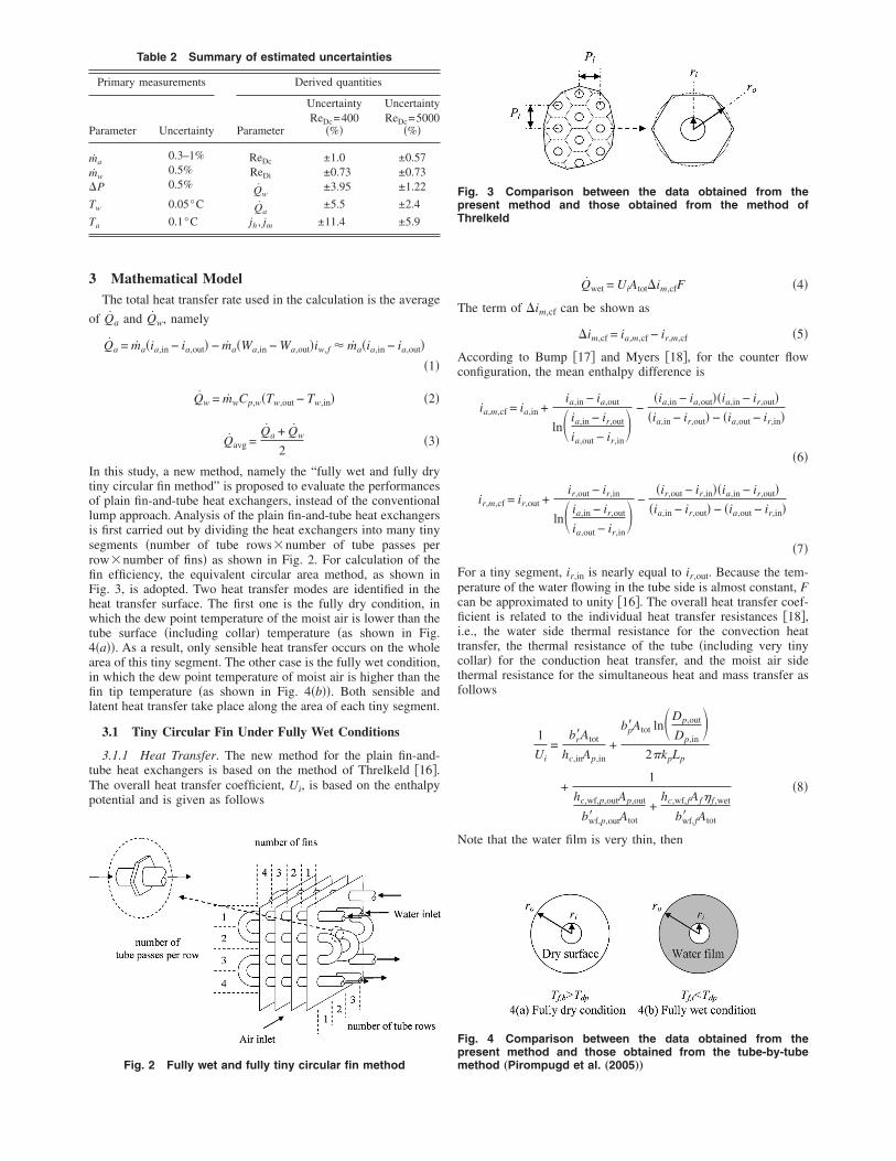
n this study, a new method, namely the “fully wet and fully dryiny circular fin method” is proposed to evaluate the performancesf plain fin-and-tube heat exchangers, instead of the conventionalump approach. Analysis of the plain fin-and-tube heat exchangerss first carried out by dividing the heat exchangers into many tinyegments �number of tube rows�number of tube passes perow�number of fins� as shown in Fig. 2. For calculation of then efficiency, the equivalent circular area method, as shown inig. 3, is adopted. Two heat transfer modes are identified in theeat transfer surface. The first one is the fully dry condition, inhich the dew point temperature of the moist air is lower than the
ube surface �including collar� temperature �as shown in Fig.�a��. As a result, only sensible heat transfer occurs on the wholerea of this tiny segment. The other case is the fully wet condition,n which the dew point temperature of moist air is higher than then tip temperature �as shown in Fig. 4�b��. Both sensible and
atent heat transfer take place along the area of each tiny segment.
3.1 Tiny Circular Fin Under Fully Wet Conditions
3.1.1 Heat Transfer. The new method for the plain fin-and-ube heat exchangers is based on the method of Threlkeld �16�.he overall heat transfer coefficient, Ui, is based on the enthalpyotential and is given as follows
Table 2 Summary of estimated uncertainties
Primary measurements Derived quantities
arameter Uncertainty Parameter
UncertaintyReDc=400
�%�
UncertaintyReDc=5000
�%�
˙ a0.3–1% ReDc ±1.0 ±0.57
˙ w0.5% ReDi ±0.73 ±0.73
P 0.5% Qw±3.95 ±1.22
w 0.05°C Qa±5.5 ±2.4
a 0.1°C jh , jm ±11.4 ±5.9
Fig. 2 Fully wet and fully tiny circular fin method
Qwet = UiAtot�im,cfF �4�
The term of �im,cf can be shown as
�im,cf = ia,m,cf − ir,m,cf �5�
According to Bump �17� and Myers �18�, for the counter flowconfiguration, the mean enthalpy difference is
ia,m,cf = ia,in +ia,in − ia,out
ln� ia,in − ir,out
ia,out − ir,in� −
�ia,in − ia,out��ia,in − ir,out��ia,in − ir,out� − �ia,out − ir,in�
�6�
ir,m,cf = ir,out +ir,out − ir,in
ln� ia,in − ir,out
ia,out − ir,in� −
�ir,out − ir,in��ia,in − ir,out��ia,in − ir,out� − �ia,out − ir,in�
�7�
For a tiny segment, ir,in is nearly equal to ir,out. Because the tem-perature of the water flowing in the tube side is almost constant, Fcan be approximated to unity �16�. The overall heat transfer coef-ficient is related to the individual heat transfer resistances �18�,i.e., the water side thermal resistance for the convection heattransfer, the thermal resistance of the tube �including very tinycollar� for the conduction heat transfer, and the moist air sidethermal resistance for the simultaneous heat and mass transfer asfollows
1
Ui=
br�Atot
hc,inAp,in+
bp�Atot ln�Dp,out
Dp,in�
2�kpLp
+1
hc,wf,p,outAp,out
bwf,p,out� Atot
+hc,wf,fAf� f ,wet
bwf,f� Atot
�8�
Note that the water film is very thin, then
Fig. 3 Comparison between the data obtained from thepresent method and those obtained from the method ofThrelkeld
Fig. 4 Comparison between the data obtained from thepresent method and those obtained from the tube-by-tube
method „Pirompugd et al. „2005……
yAyCvsG
a
Tirq
TmpotstrsttneT
TfieTt
w
Etl
hc,wf,f =1
Cp,a
bwf,f� hc,out
+ywf
kwf
�9�
hc,wf,p,out =1
Cp,a
bwf,p,out� hc,out
+ywf
kwf
�10�
wf in Eqs. �9� and �10� represents the thickness of the water film.constant of 0.013 cm was proposed by Myers �18�. In practice,
wf/kwf accounts for only 0.5–5% compared to Cp,a /bwf,f� hc,out and
p,a /bwf,p,out� hc,out, and has often been neglected by previous in-estigators. As a result, this term is not included in the final analy-is. The water-side heat transfer coefficient was presented bynielinski �19�
hc,in =�f in/2��Rein − 1000�Prin
1.07 + 12.7f in/2�Prin2/3 − 1�
·kw
Dp,in�11�
nd the friction factor, f i is
f in =1
�1.58 ln Rein − 3.28�2 �12�
he Reynolds number used in Eqs. �11� and �12� is based on thenside tube diameter. In Eq. �8� bp�, br�, bwf,f� , and bwf,p,out� are theatios of enthalpy to temperature that must be evaluated. Theuantities bp� and br� can be calculated as
br� =ir,p,in,m,cf − ir,m,cf
Tp,in,m,cf − Tr,m,cf�13�
bp� =ir,p,out,m,cf − ir,p,in,m,cf
Tp,out,m,cf − Tp,in,m,cf�14�
he values of bwf,f� and bwf,p,out� denote the slopes of the saturatedoist air enthalpy curved evaluated at the mean water film tem-
eratures of the fin and outside tube surfaces, respectively. With-ut loss of generality, bwf,f� and bwf,p,out� can be approximated byhe slope of the saturated moist air enthalpy curved at the mean finurface temperature �Tf ,m,cf� and the mean outside tube surfaceemperature �Tp,out,m,cf� �8�. With the assumption of the smallange of temperature, the enthalpy of saturated air may be repre-ented as the linear function of the temperature. Then, the slope ofhe saturated moist air enthalpy can be calculated �16�. However,he evaluation of bwf,f� requires a trial and error procedure andeeds the information of wet fin efficiency. Notice that the wet finfficiency �� f ,wet� is based on the enthalpy difference proposed byhrelkeld �16�
� f ,wet =ia,m,cf − ir,f ,m,cf
ia,m,cf − ir,p,out,m,cf�15�
he use of the enthalpy potential equation greatly simplifies then efficiency calculation as illustrated by Kandlikar �20�. How-ver, the original formulation of the wet fin efficiency byhrelkeld �16� was for straight fin configuration. For a circular fin,
he wet fin efficiency is �8�
� f ,wet =2ri
MT�ro2 − ri
2�K1�MTri�I1�MTro� − K1�MTro�I1�MTri�
K1�MTro�I0�MTri� + K0�MTri�I1�MTro���16�
here
MT =2hc,wf,f
kft�17�
valuation of bwf,f� requires a trial and error procedure. For therial and error procedure, ir,f ,m,cf must be calculated using the fol-
owing equationir,f ,m,cf = ia,m,cf − � f ,wet�1 − UiAtot br�
hc,inAp,in
+
bp� ln�Dp,out
Dp,in�
2�kpLp���im,cf �18�
An algorithm for solving the heat transfer characteristic for thefully wet condition is given as follows:
1. Based on the information, calculate the average heat transfer
rate �Qavg� using Eq. �3�;2. Assume a hc,out for all elements;3. Calculate the heat transfer characteristic for each segment
with the following procedures:
• 3.1 Calculate the water-side heat transfer coefficient ofhc,in using Eq. �11�;
• 3.2 Assume an outlet moist air enthalpy of the calculatedsegment;
• 3.3 Calculate ia,m,cf and ir,m,cf by Eqs. �6� and �7�;• 3.4 Assume Tp,in,m,cf and Tp,out,m,cf;• 3.5 Calculate br� /hc,inAp,in and
bp� ln�Dp,out /Dp,in� /2�kpLp;• 3.6 Assume a Tf ,m,cf;• 3.7 Calculate the � f ,wet using Eq. �16�;• 3.8 Calculate Ui from Eq. �8�;• 3.9 Calculate ir,f ,m,cf by Eq. �18�;• 3.10 Calculate Tf ,m,cf from ir,f ,m,cf;• 3.11 If Tf ,m,cf, calculated in Step 3.10, is not equal to that
assumed in step 3.6, the calculation Steps 3.7–3.10 willbe repeated with Tf ,m,cf calculated in Step 3.10 untilTf ,m,cf is constant;
• 3.12 Calculate the heat transfer rate �Q� of this segment;• 3.13 Calculate Tp,in,m,cf and Tp,out,m,cf from the water-side
convection heat transfer and the conduction heat transferof the tube;
• 3.14 If Tp,in,m,cf and Tp,out,m,cf, calculated from Step 3.13,are not equal to the assumed values in Step 3.4, the cal-culation of Steps 3.5–3.13 will be repeated with Tp,in,m,cfand Tp,out,m,cf being calculated in Step 3.13 until Tp,in,m,cfand Tp,out,m,cf are fixed;
• 3.15 Calculate the outlet moist air enthalpy by Eq. �1�and the outlet water temperature by Eq. �2�; and
• 3.16 If the outlet moist air enthalpy calculated in Step3.15 is not equal to that assumed value in Step 3.2, thecalculation Steps 3.3–3.15 will be repeated with the out-let moist air enthalpy calculated from Step 3.15 until theoutlet moist air enthalpy is fixed.
4. If the summation of the heat transfer rate �Q� for all ele-
ments is not equal to Qavg, hc,out will be assumed with a newvalue and the calculation Step 3 will be repeated until the
summation of the heat transfer rate �Q� for all elements is
equal to Qavg.
3.1.2 Mass Transfer. For the fully wet condition, the coolingand dehumidifying of the moist air by a cold surface involves thesimultaneous heat and mass transfer and can be described by theprocess line equation �SI unit� from Threlkeld �16�
dia
dWa= R
�ia − iwf��Wa − Wwf�
+ �iw,g − 2501R� �19�
and

Hnc�dmsea
Nthg
De
d fr
R =hc,out
hd,outCp,a�20�
owever, for the present fin-and-tube heat exchanger, Eq. �19� didot correctly describe the dehumidification process on the psy-hrometric chart. This is because the saturated moist air enthalpyiwf� at the mean water film temperature on the fin surface isifferent from that at the outside tube surface. In this regard, aodification of the process line on the psychrometric chart corre-
ponding to the fin-and-tube heat exchangers is made. From thenergy balance of the dehumidification, the rate equation can berrived at by following expression
madia =hc,out
Cp,adAp,out�ia,m − ir,p,out,m� +
hc,out
Cp,adAf�ia,m − ir,f ,m�
�21�
ote that the first term on the right-hand side denotes the heatransfer for the outside tube part, whereas the second term is theeat transfer for the fin part. Conservation of the water condensateives
ma dWa = hd,out dAp,out�Wa,m − Wr,p,out,m� + hd,out dAf�Wa,m − Wr,f ,m��22�
ividing the equation of the heat transfer rate �Eq. �21�� by the
Fig. 5 jh and jm obtaine
quation of the mass transfer rate �Eq. �22�� yields
dia
dWa=
R · �ia,m − ir,p,out,m� + R · �� − 1� · �ia,m − ir,f ,m��Wa,m − Wr,p,out,m� + �� − 1� · �Wa,m − Wr,f ,m�
�23�
where
� =Atot
Ap,out�24�
By assuming a value of the ratio of heat transfer to mass transfer,R, and by integrating Eq. �23� with an iterative algorithm, themoist air-side convective mass transfer performance can be ob-tained. Analogous procedures for obtaining the mass transfer char-acteristic are given as
1. Obtain Wr,p,out,m and Wr,f ,m from ir,p,out,m and ir,f ,m fromthose calculations of the heat transfer;
2. Assume a value of R;3. Calculations are performed from the first element to the last
element, employing the following procedures:
• 3.1 Assume an outlet moist air humidity ratio;• 3.2 Calculate the outlet moist air humidity ratio of each
element by Eq. �23�; and• 3.3 If the outlet moist air humidity ratio obtained from
Step 3.2 is not equal to the assumed value of Step 3.1,the calculation Steps 3.1–3.2 will be repeated.
4. If the average of the outlet moist air humidity ratio for all
om the present method
elements of the last row is not equal to the total outlet moist
c
�he
T
Am
air humidity ratio, assume a new R value and the calculationStep 3 will be repeated until the average of the outlet moistair humidity ratio of the last row is equal to the outlet moistair humidity ratio.
3.2 Tiny Circular Fin Under Fully Dry Condition
3.2.1 Heat Transfer. The total rate of heat transfer used in the
alculation is averaged from the air side �Qa� and the water side
Qw� as shown in Eq. �3�. For the fully dry condition, the overalleat transfer coefficient, UT, is based on the temperature differ-nce and given as follows
Qdry = UTAtot�Tm,cfF �25�
he term of �Tm,cf can be shown as
�Tm,cf = Ta,m,cf − Tw,m,cf �26�
ccording to Bump �17�, for the counter flow configuration, theean temperature difference is
Ta,m,cf = Ta,in +Ta,in − Ta,out
ln�Ta,in − Tw,out
Ta,out − Tw,in� −
�Ta,in − Ta,out��Ta,in − Tw,out��Ta,in − Tw,out� − �Ta,out − Tw,in�
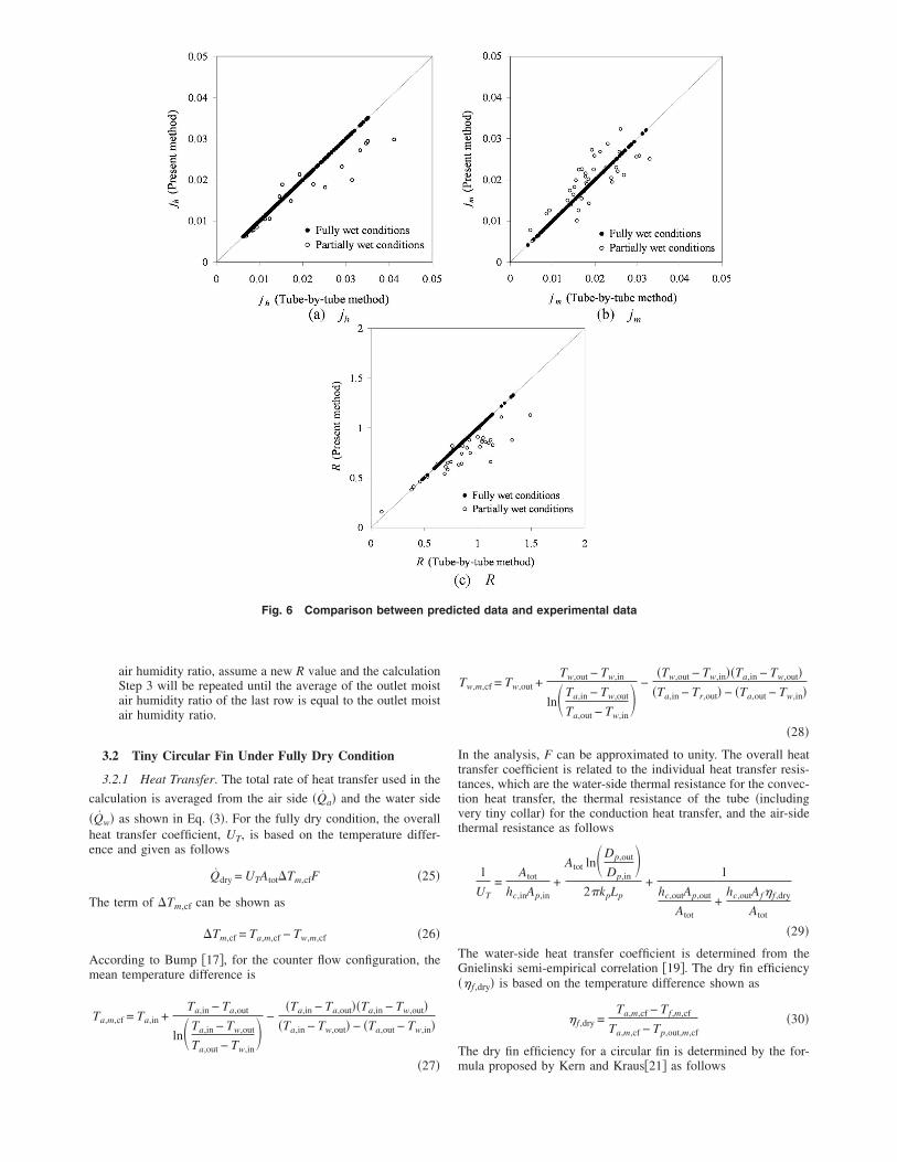
Fig. 6 Comparison between pre
�27�
Tw,m,cf = Tw,out +Tw,out − Tw,in
ln�Ta,in − Tw,out
Ta,out − Tw,in� −
�Tw,out − Tw,in��Ta,in − Tw,out��Ta,in − Tr,out� − �Ta,out − Tw,in�
�28�
In the analysis, F can be approximated to unity. The overall heattransfer coefficient is related to the individual heat transfer resis-tances, which are the water-side thermal resistance for the convec-tion heat transfer, the thermal resistance of the tube �includingvery tiny collar� for the conduction heat transfer, and the air-sidethermal resistance as follows
1
UT=
Atot
hc,inAp,in+
Atot ln�Dp,out
Dp,in�
2�kpLp+
1
hc,outAp,out
Atot+
hc,outAf� f ,dry
Atot
�29�
The water-side heat transfer coefficient is determined from theGnielinski semi-empirical correlation �19�. The dry fin efficiency�� f ,dry� is based on the temperature difference shown as
� f ,dry =Ta,m,cf − Tf ,m,cf
Ta,m,cf − Tp,out,m,cf�30�
The dry fin efficiency for a circular fin is determined by the for-
ted data and experimental data
dicmula proposed by Kern and Kraus�21� as follows

w
Af
� f ,dry =2ri
Mm�ro2 − ri
2�K1�Mmri�I1�Mmro� − K1�Mmro�I1�Mmri�
K1�Mmro�I0�Mmri� + K0�Mmri�I1�Mmro���31�
here
Mm =2hc,out
kft�32�
n algorithm for solving the heat transfer characteristic for theully dry condition is given as follows:
1. Based on the information, calculate the average heat transfer
rate �Qavg� using Eq. �3�;2. Assume a hc,out for all elements;3. Calculate the heat transfer characteristic for each segment
Fig. 7 jh and jm obtaine
with the following procedures:
• 3.1 Calculate the tube-side heat transfer coefficient of hiusing Eq. �11�;
• 3.2 Assume an outlet-air enthalpy of the calculated seg-ment;
• 3.3 Calculate Ta,m,cf and Tw,m,cf by Eqs. �27� and �28�;• 3.4 Calculate 1 /hc,inAp,in and ln�Dp,out /Dp,in� /2�kpLp;• 3.5 Calculate the � f ,dry using Eq. �31�;• 3.6 Calculate UT from Eq. �29�;• 3.7 Calculate Qdry from Eq. �25� of this segment;• 3.8 Calculate the outlet-air enthalpy and the outlet-water
temperature from Qdry obtained in Step 3.7; and• 3.9 If the outlet-air enthalpy obtained in Step 3.8 is not
equal to that assumed in Step 3.2, the calculation Steps3.3–3.8 will be repeated with the outlet-air enthalpy ob-tained in Step 3.8 until the outlet-air enthalpy reaches a
om the present method
d frconstant value.

(pb
4
tppstiommbcapctFiTwbsatftaaTwf
tchttCd
4. If the summation of the heat transfer rate �Q� for all ele-
ments is not equal to Qavg, hc,out will be assumed with a newvalue and the calculation Step 3 will be repeated until the
summation of the heat transfer rate �Q� for all elements is
equal to Qavg.
3.3 Chilton–Colburn j-Factor for Heat and Mass Transferjh and jm). The heat and mass transfer characteristics for thelain fin-and-tube heat exchangers from the experimentation wille presented in the forms of the dimensionless groups
jh =hc,out
Ga,max Cp,aProut
2/3 �33�
jm =hd,out
Ga,maxScout
2/3 �34�
Results and DiscussionThe heat and mass transfer characteristics for the plain fin-and-
ube heat exchangers are presented in terms of the dimensionlessarameters jh and jm, respectively. The test results are first com-ared with the original Threlkeld method. The comparisons arehown in Figs. 5�a�, 5�b�, and 5�c�. For the heat transfer charac-eristic, one can see in Fig. 5�a� that the original lumped approachs in fair agreement with the present discretized approach �77.86%f jh within ±20%�. However, the jh obtained by the presentethod is slightly lower than that obtained by the Threlkeldethod. There are two reasons for this result. The first one is
ecause the jh obtained by the present method is based on a dis-retized approach. In addition, the original Threlkeld method ispplicable for fully wet surfaces only. For those data that are inartially wet conditions, an underestimation of the wet fin effi-iency by the lumped Threlkeld method gives rise to a higher heatransfer coefficient, thereby yielding a higher jh value accordingly.or the reduced results of the mass transfer characteristic, shown
n Fig. 5�b�, one can see a much larger departure to the originalhrelkeld method relative to the present method �76.72% of jmithin ±30%�. This is attributed to the original Threlkeld methodeing more suitable for counter flow arrangements. By compari-on with the tube-by-tube method proposed by Pirompugd etl.�9�, as shown in Figs. 6�a�, 6�b�, and 6�c�, the heat and massransfer characteristics obtained by the present method for theully wet conditions are equal to those obtained by the tube-by-ube method. However, for the partially wet conditions, the heatnd mass transfer characteristics obtained by the present methodre different from those obtained from the tube-by-tube method.his is because the present method takes into account partiallyet conditions, whereas the tube-by-tube method is more suitable
or fully wet conditions.A typical plot for examination of the influence of the inlet rela-
ive humidity and the fin spacing on the heat and mass transferharacteristics are shown in Fig. 7. As seen in Figs. 7�a�–7�c�, theeat transfer characteristic is relatively insensitive to the inlet rela-ive humidity and fin spacing. For the influence of fin spacing onhe heat transfer characteristic having N=1 or N=2, Wang andhi�22� showed that the results are different from those in fullyry conditions. Based on the numerical simulation by Torikoshi et
Dc Dc Dc
al.�23�, they found that the vortex forming behind the tube can besuppressed and the entire flow region can be kept steady andlaminar when the fin spacing is small enough. A further increaseof fin spacing would result in a noticeable increase of cross-streamwidth of the vortex region behind the tube. As a result, the heattransfer characteristic decreases with the increase of fin spacingfor the one-row configuration, indicating a detectable influence offin spacing. However, it can be seen that the effect of fin spacingon the heat transfer characteristic is comparatively small for thewet fin surface. Apparently it is attributed to the presence of con-densate that provides a good air flow mixing even at larger finspacing. In fact, the difference in the heat transfer characteristicbecomes even more negligible when the number of tube rows isincreased. With the increase in the number of tube rows, the con-densate blow-off phenomenon from the preceding row is blockedby the subsequent row.
As seen in Figs. 7�d�–7�f�, the influence of the inlet relativehumidity on the mass transfer characteristics is rather small whenthe fin spacing is sufficiently large ��2.0 mm�. However, at asmaller fin spacing �sample Nos. 1–3, 6–8, and 11–13� one canobserve a slight decrease of jm when the inlet relative humidity isincreased from 50% to 90%. The slight decrease in the mass trans-fer characteristic with the inlet relative humidity at dense fin spac-ing may be described with the condensate retention phenomenon.Yoshii et al.�24� conducted a flow pattern observation of the airflow across tube bank, their results indicating that the blockage ofthe tube rows by the condensate retention may hinder the perfor-mance of the heat exchangers. Thus, one can see a slight drop inthe mass transfer characteristic. However, a considerable increasein the mass transfer characteristic is encountered when relativehumidity �RH�=0.5 and ReDc�1000. This is attributed to theblow-off condensate by flow inertia which makes more room forwater vapor to condense along the surface.
The dehumidifying process involves heat and mass transfer si-multaneously. If mass transfer data are unavailable, it is conve-nient to employ the analogy between the heat and mass transfer.The existence of the heat and mass analogy is due to the fact thatconduction and diffusion in a liquid are governed by physical lawsof identical mathematical forms. Therefore, for an air–water vapormixture, the ratio of hc,o /hd,oCp,a is generally around unity. Theterm in Eq. �20� is approximately equal to unity for dilute mix-tures like water vapor in air near the atmospheric pressure �tem-perature well below the corresponding boiling point�. The validityof this approximation relies heavily on the mass transfer rate. Theexperimental data of Hong and Webb �25� indicated that this valuewas between 0.7 and 1.1, Seshimo et al.�7� gave a value of 1.1.Eckels and Rabas �26� also reported a similar value of 1.1–1.2 fortheir test results of fin-and-tube heat exchangers having plain fingeometry. The aforementioned studies all showed the applicabilityof the approximation. In the present study, we notice that thevalues of hc,o /hd,oCp,a are generally between 0.6 and 1.2.
It is obvious from the test results shown that no single curvecan describe the jh and jm factors. As a result, using a multiplelinear regression technique in a range of experimental data. �300�ReDc�5500�, the appropriate correlations of jh and jm based onthe present data are as follows
1. –1 row and fully wet condition
jh,1 = 0.6189� Sp
Dc�−0.4176� Pl
Dc�−0.7834� Pt
Dc�0.9802
Re�0.3232Sp
Dc+0.04332
Pl
Dc−0.07983
Pt
Dc−0.6125� �35�
jm,1 = 0.2094� Sp �−0.3507� Pl �−1.6856� Pt �1.9988
Re�0.3264Sp
Dc+0.09569
Pl
Dc−0.09808
Pt
Dc−0.5523� �36�

ef
7c
5
toc
R1 = 2.8804� Sp
Dc�0.00973� Pl
Dc�0.6203� Pt
Dc�−0.8043
Re�−0.0671Sp
Dc−0.0295
Pl
Dc+0.00847
Pt
Dc−0.06323� �37�
2. –1 row and partially wet condition �70% �Awet /Atpt�100% �
jh,1,p = 1.5638jh,1�Awet
Atot�−0.5554
Re�0.1132Sp
Dc−0.01953
Pl
Dc+0.003906
Pt
Dc−0.02734� �38�
jm,1,p = 0.3384jm,1�Awet
Atot�−0.5072
Re�0.09427Sp
Dc−0.00001
Pl
Dc+0.04688
Pt
Dc−0.00001� �39�
R1,p = 1.5165R1�Awet
Atot�−0.04714
Re�0.02054Sp
Dc−0.02344
Pl
Dc+0.03906
Pt
Dc−0.01563� �40�
3. –2, 4 and 6 rows and fully wet condition
jh,N = 0.3301jh,1� Sp
Dc�0.4683� Pl
Dc�0.3549� Pt
Dc�0.8906
Re�−0.3611Sp
Dc−0.01713
Pl
Dc−0.01710
Pt
Dc+0.2514� �41�
jm,N = 0.08575jm,1� Sp
Dc�0.2051� Pl
Dc�0.8187� Pt
Dc�1.425
Re�−0.3503Sp
Dc−0.03997
Pl
Dc−0.054360
Pt
Dc+0.4086� �42�
RN = 5.0207R1� Sp
Dc�0.1977� Pl
Dc�−0.2889� Pt
Dc�−1.0349
Re�0.04954Sp
Dc+0.01036
Pl
Dc+0.06751
Pt
Dc−0.2272� �43�
4. –2, 4 and 6 rows and partially wet condition �60% �Awet /Atpt�100% �
jh,N,p = 1.1833� jh,N
jh,1��Awet
Atot�−0.1258
Re�0.0749Sp
Dc−0.01844
Pl
Dc−0.00865
Pt
Dc−0.56937� �44�
jm,N,p = 0.4406� jm,N
jm,1��Awet
Atot�−0.3742
Re�0.2132Sp
Dc−0.03656
Pl
Dc+0.02305
Pt
Dc−0.4906� �45�
RN,p = 2.1662�RN
R1��Awet
Atot�0.2434
Re�−0.1486Sp
Dc+0.01579
Pl
Dc−0.03139
Pt
Dc−0.05805� �46�
Detailed comparisons of the proposed correlations against thexperimental data are shown in Figs. 8�a�, 8�b�, and 8�c�. It isound that Eqs. �35�, �38�, �41�, and �44� can describe 96.95% of
jh within ±20%. Equations �36�, �39�, �42�, and �45� can describe7.49% of jm within ±20%. Equations �37�, �40�, �43�, and �46�an describe 80.92% of R within ±20%.
ConclusionsThis study experimentally examines the heat and mass charac-
eristics of 18 fin-and-tube heat exchangers having plain fin ge-metry. On the basis of previous discussions, the following con-lusions are made:
1. A fully wet and fully dry tiny circular fin method is proposedin this study for reducing the test results. This predictiveability of the proposed method is superior to previous stud-ies;
2. It is found that the reduced results for the heat transfer char-acteristic by the present method are insensitive to changes ofthe inlet humidity. The effect of the fin spacing on the masstransfer characteristic is rather small when the fin spacing islarger than 2.0 mm. However, at a smaller fin spacings, jmdecreases slightly when the relative humidity increases;
3. Comparatively, the heat transfer characteristic is indepen-dent of the fin spacing. This is because the presence of con-densate plays a role in altering the air flow pattern within theheat exchanger, resulting in better mixing characteristics.For N�4, the heat transfer characteristic is about the same,even when the fin surface is partially wet;
4. For one and two row configurations, the effect of the relative
humidity on the mass transfer characteristic becomes morepronounced when the partially wet condition has takenplace; and
5. Correlations are proposed for the present fin-and-tube heatexchanger having plain fin configurations. These correla-tions can describe 96.95% of jh within ±20%, 77.49% of jmwithin ±20%, and 80.92% of R within ±15%.
AcknowledgmentThe authors are indebted to the Thailand Research Fund �TRF�
and the Energy R&D Foundation funding from the Bureau ofEnergy of the Ministry of Economic Affairs, Taiwan for support-ing this study.
NomenclatureAf surface area of the fin, m2
Ap,in inside surface area of the tube, m2
Ap,out outside surface area of the tube, m2
Atot total surface area that is the summation of Afand Ap,out, m2
Awet wet fin surface area, m2
bp� slope of the saturated moist air enthalpycurved between the mean inside and outsidetube surface temperatures, J kg−1 K−1
br� slope of the saturated moist air enthalpycurved between the mean water temperatureand the mean inside tube surface temperature,
−1 −1
J kg K
dic
bwf,f� slope of the saturated moist air enthalpycurved at the mean water film temperature ofthe fin surface, J kg−1 K−1
bwf,p,out� slope of the saturated moist air enthalpycurved at the mean water film temperature ofthe outside tube surface, J kg−1 K−1
Cp,a moist air specific heat at constant pressure,J kg−1 K−1
Cp,w water specific heat at constant pressure,J kg−1 K−1
Dc collar diameter, mDp,in inside tube diameter, m
Dp,out outside tube diameter �include very tiny collar�that is equal to the collar diameter, m
F correction factorFp fin pitch, mf in water side friction factor
Ga,max moist air maximum mass velocity based on theminimum flow area, kg m−2 s−1
hc,in water side convection heat transfer coefficient,W m−2 K−1
hc,out moist air side convection heat transfer coeffi-cient, W m−2 K−1
hc,wf,f heat transfer coefficient for the heat transferbetween the moist air and fin surface,
−2 −1
Fig. 8 Comparison between pre
W m K
hc,wf,p,out heat transfer coefficient for the heat transferbetween the moist air and outside tube surface,W m−2 K−1
hd,out moist air side convection mass transfer coeffi-cient, kg m−2 s−1
I0 modified Bessel function solution of the firstkind, order 0.
I1 modified Bessel function solution of the firstkind, order 1.
ia moist air enthalpy, J kg−1
ia,in inlet moist air enthalpy, J kg−1
ia,m mean moist air enthalpy, J kg−1
ia,m,cf mean moist air enthalpy for the counter flowconfiguration, J kg−1
ia,out outlet moist air enthalpy, J kg−1
ir,f ,m mean saturated moist air enthalpy at the meanfin surface temperature, J kg−1
ir,f ,m,cf mean saturated moist air enthalpy at the meanfin surface temperature for the counter flowconfiguration, J kg−1
ir,in saturated moist air enthalpy at the inlet watertemperature, J kg−1
ir,m,cf mean saturated moist air enthalpy at the meanwater temperature for the counter flow con-figuration, J kg−1
ted data and experimental data
ir,out saturated moist air enthalpy at the outlet watertemperature, J kg−1
ir,p,in,m,cf mean saturated moist air enthalpy at the meaninside tube surface temperature for the counterflow configuration, J kg−1
ir,p,out,m mean saturated moist air enthalpy at the meanoutside tube surface temperature, J kg−1
ir,p,out,m,cf mean saturated moist air enthalpy at the meanoutside tube surface temperature for thecounter flow configuration, J kg−1
iwf saturated moist air enthalpy at the water filmtemperature, J kg−1
iw,f specific enthalpy of the saturated water liquid,J kg−1
iw,g specific enthalpy of the saturated water vapor,J kg−1
jh Colburn heat transfer group or Chilton–Colburn j factor for the heat transfer
jm Colburn mass transfer group or Chilton–Colburn j factor for the mass transfer
K0 modified Bessel function solution of the sec-ond kind, order 0
K1 modified Bessel function solution of the sec-ond kind, order 1
kf thermal conductivity of the fin, W m−1 K−1
kp thermal conductivity of the tube, W m−1 K−1
kwf thermal conductivity of the water, W m−1 K−1
kwf thermal conductivity of the water film,W m−1 K−1
Lp tube length, mma moist air mass flow rate, kg/smw water mass flow rate, kg/s
N number of tube rowsPl longitudinal tube pitch, m
Prin water-side Prandtl numberProut moist air-side Prandtl number
Pt transverse tube pitch, m
Qa moist air-side heat transfer rate, W
Qavg average heat transfer rate between the moist airand water sides, W
Qw water-side heat transfer rate, W
Qwet heat transfer rate for a fully wet segment, WR ratio of the convection heat transfer character-
istic to the convection mass transfer character-istic for the simultaneous convection heat andmass transfer
ReDc moist air-side Reynolds number based on thecollar diameter
Rein water-side Reynolds numberRH inlet relative humidity of the moist air
ri inside fin radius for the equivalent circular finequal to the outside tube �include collar�radius, m
ro outside fin radius for the equivalent circularfin, m
Scout moist air-side Schmidt numberSp fin spacing, mTa moist air temperature, K
Ta,in inlet moist air temperature, KTa,m,cf mean moist air temperature for the counter
flow configuration, KTa,out outlet moist air temperature, K
Tdp dew point temperature of the moist air, KTf ,b fin base temperature, KTf ,t fin tip temperature, K
Tf ,m,cf mean fin temperature, K
Tp,in,m,cf mean inside-tube surface temperature for thecounter flow configuration, K
Tp,out,m,cf mean outside-tube surface temperature for thecounter flow configuration, K
Tr,m,cf mean water temperature for the counter flowconfiguration, K
Tw water temperature, KTw,in inlet water temperature, K
Tw,out outlet water temperature, KTw,m,cf mean water temperature for the counter flow
configuration, Kt fin thickness, m
Ui overall heat transfer coefficient based on themean enthalpy difference, kg m−2 s−1
UT overall heat transfer coefficient based on themean temperature difference, W m−2 K−1
Wa moist air humidity ratioWa,in inlet moist air humidity ratioWa,m mean moist air humidity ratio
Wa,out outlet moist air humidity ratioWr,f ,m mean saturated moist air humidity ratio at the
mean fin surface temperatureWr,p,out,m mean saturated moist air humidity ratio at the
mean outside tube surface temperatureWwf saturated moist air humidity ratio at the water
film temperatureywf thickness of the water film, m
� f ,dry dry fin efficiency� f ,wet wet fin efficiency�im,cf logarithmic mean enthalpy difference across
the heat exchanger for the counter flowdouble-pipe configuration with hot and coldfluid enthalpies, J kg−1
�P difference pressure, Pa�Tm,cf logarithmic mean temperature difference across
the heat exchanger for the counter flowdouble-pipe configuration with hot and coldfluid temperatures, K
References�1� ARI, 2001, “Forced Circulation Air-Cooling and Air-Heating Coils,” Air Con-
ditioning and Refrigeration Institute, VA, Standard No. 410.�2� McQuiston, F. C., 1978, “Heat Mass and Momentum Transfer Data for Five
Plate-Fin Tube Transfer Surface,” ASHRAE Trans., 84, pp. 266–293.�3� McQuiston, F. C., 1978, “Correlation of Heat, Mass and Momentum Transport
Coefficients for Plate-Fin-Tube Heat Transfer Surfaces With Staggered Tubes,”ASHRAE Trans., 84, pp. 294–309.
�4� Mirth, D. R., and Ramadhyani, S., 1993, “Prediction of Cooling-Coils Perfor-mance Under Condensing Conditions,” Int. J. Heat Fluid Flow, 14�4�, pp.391–400.
�5� Mirth, D. R., and Ramadhyani, S., 1994, “Correlations for Predicting the Air-Side Nusselt Numbers and Friction Factors in Chilled-Water Cooling Coils,”Exp. Heat Transfer, 7, pp. 143–162.
�6� Fu, W. L., Wang, C. C., and Chang, C. T., 1995, “Effect of Anti-CorrosionCoating on the Thermal Characteristics of a Louvered Finned Heat ExchangerUnder Dehumidifying Condition,” Advances in Enhanced Heat/Mass Transferand Energy Efficiency, ASME HTD, Vol. 320/PID-Vol. 1, pp. 75–81.
�7� Seshimo, Y., Ogawa, K., Marumoto, K., and Fujii, M., 1988, “Heat and MassTransfer Performances on Plate Fin and Tube Heat Exchangers With Dehu-midification,” Trans. Jpn. Soc. Mech. Eng., Ser. A, 54�499�, pp. 716–721.
�8� Wang, C. C., Hsieh, Y. C., and Lin, Y. T., 1997, “Performance of Plate FinnedTube Heat Exchangers Under Dehumidifying Conditions,” J. Heat Transfer,119, pp. 109–117.
�9� Pirompugd, W., Wongwises, S., and Wang, C. C., 2005, “A Tube-by-TubeReduction Method for Simultaneous Heat and Mass Transfer Characteristicsfor Plain Fin-and-Tube Heat Exchangers in Dehumidifying Conditions,” HeatMass Transfer, 41�8�, pp. 756–765.
�10� Pirompugd, W., Wongwises, S., and Wang, C. C., 2006, “Simultaneous Heatand Mass Transfer Characteristics for Wavy Fin-and-Tube Heat ExchangersUnder Dehumidifying Conditions,” Int. J. Heat Mass Transfer, 49, pp. 132–143.
�11� Xia, Y., and Jacobi, A. M., 2005, “Air-Side Data Interpretation and Perfor-mance Analysis for Heat Exchangers With Simultaneous Heat and Mass Trans-fer: Wet and Frosted Surfaces,” Int. J. Heat Fluid Flow, 48, pp. 5089–5102.
�12� ASHRAE, 1987, “Standard Methods for Laboratory Air-Flow Measurement,”
American Society of Heating, Refrigerating and Air-Conditioning Engineers,Inc., Atlanta, GA, Standard No. 41.2.
�13� ASHRAE, 1986, “Standard Method for Temperature Measurement,” AmericanSociety of Heating, Refrigerating and Air-Conditioning Engineers, Inc., At-lanta, GA, Standard No. 41.1.
�14� ASHRAE, 2000, “Method of Testing Forced Circulation Air Cooling and AirHeating Coils,” American Society of Heating, Refrigerating and Air-Conditioning Engineers, Inc., Atlanta, GA, Standard No. 33, pp. 33–78.
�15� Moffat, R. J., 1988, “Describing the Uncertainties in Experimental Results,”Exp. Therm. Fluid Sci., 1, pp. 3–17.
�16� Threlkeld, J. L., 1970, Thermal Environmental Engineering, Prentice–Hall,New York.
�17� Bump, T. R., 1963, “Average Temperatures in Simple Heat Exchangers,”ASME J. Heat Transfer, 85�2�, pp. 182–183.
�18� Myers, R. J., 1967, “The Effect of Dehumidification on the Air-Side HeatTransfer Coefficient for a Finned-Tube Coil,” M.S. thesis, University of Min-nesota, Minneapolis, MN.
�19� Gnielinski, V., 1976, “New Equation for Heat and Mass Transfer in TurbulentPipe and Channel Flow,” Int. Chem. Eng., 16, pp. 359–368.
�20� Kandlikar, S. G., 1990, “Thermal Design Theory for Compact Evaporators,”
Compact Heat Exchangers—A Festschrift for A. L. London, R. K. Shah, A. D.Kraus, and D. Metzger, eds., Hemisphere, New York, pp. 245–286.
�21� Kern, D. Q., and Kraus, A. D., 1972, Extended Surface Heat Transfer,McGraw–Hill, New York, pp. 102–106.
�22� Wang, C. C., and Chi, K. U., 2000, “Heat Transfer and Friction Characteristicsof Plain Fin-and-Tube Heat Exchangers: Part I: New Experimental Data,” Int.J. Heat Mass Transfer, 43, pp. 2681–2691.
�23� Torikoshi, K., Xi, G., Nakazawa, Y., and Asano, H., 1994, “Flow and HeatTransfer Performance of a Plate-Fin and Tube Heat Exchanger �1st Report:Effect of Fin Pitch�,” Proceedings 10th International Heat Transfer Confer-ence, Brighton, UK, August 14–18, Paper No. 9-HE-16, pp. 411–416.
�24� Yoshii, T., Yamamoto, M., and Otaki, M., 1973, “Effects of Dropwise Con-densate on Wet Surface Heat Transfer of Air Cooling Coils,” Proceedings ofthe 13th Int. Congress of Refrigeration, Washington, DC, August 27, pp. 285–292.
�25� Hong, T. K., and Webb, R. L., 1996, “Calculation of Fin Efficiency for Wetand Dry Fins,” HVAC&R Res., 2�1�, pp. 27–41.
�26� Eckels, P. W., and Rabas, T. J., 1987, “Dehumidification on the Correlation ofWet and Dry Transport Process in Plate Finned-Tube Heat Exchangers,”
ASME J. Heat Transfer, 109, pp. 575–582.