A Framework for Service-Guaranteed Path Protection of … K7L3N6 (hoph, ... path selection module...
13
A Framework for Service-Guaranteed Path Protection of the Optical Internet Pin-Han Ho and H.T. Mouftah Department of Electrical and Computer Engineering, Queen's University at Kingston, Ontario, Canada, K7L3N6 (hoph, mouflah}@ece.queensu.ca TEL: (613) 533-2934 FAX: (613)533-6115 Key words: Protection and restoration, optical networks, DWDM Abstract: The ordinary path-based and link-based shared protection schemes can only provide a limited spectrum of protection services with coarse protection granularity, which will not be able to satisfy the versatile requirements of multimedia applications on the Internet in the foreseeable future. In this paper we propose a framework, Short Leap Shared Protection (SLSP), for service- guaranteed end-to-end shared protection for the optical Internet. We will show that SLSP enhances the I:N and M:N shared protection schemes in terms of scalability, flexibility and class of service. 1. INTRODUCTION The use of DWDM (dense wavelength division mUltiplexing) in the Internet backbone has opened a new era for multimedia communication networks by dynamically provisioning nearly unlimited bandwidth. The original version of this chapter was revised: The copyright line was incorrect. This has been corrected. The Erratum to this chapter is available at DOI: 10.1007/978-0-387-35491-0_28 © IFIP International Federation for Information Processing 2002 A. Jukan (ed.), Towards an Optical Internet
Transcript of A Framework for Service-Guaranteed Path Protection of … K7L3N6 (hoph, ... path selection module...

A Framework for Service-Guaranteed Path Protection of the Optical Internet
Pin-Han Ho and H.T. Mouftah Department of Electrical and Computer Engineering, Queen's University at Kingston, Ontario, Canada, K7L3N6
(hoph, mouflah}@ece.queensu.ca
TEL: (613) 533-2934 FAX: (613)533-6115
Key words: Protection and restoration, optical networks, DWDM
Abstract: The ordinary path-based and link-based shared protection schemes can only provide a limited spectrum of protection services with coarse protection granularity, which will not be able to satisfy the versatile requirements of multimedia applications on the Internet in the foreseeable future. In this paper we propose a framework, Short Leap Shared Protection (SLSP), for serviceguaranteed end-to-end shared protection for the optical Internet. We will show that SLSP enhances the I:N and M:N shared protection schemes in terms of scalability, flexibility and class of service.
1. INTRODUCTION
The use of DWDM (dense wavelength division mUltiplexing) in the Internet backbone has opened a new era for multimedia communication networks by dynamically provisioning nearly unlimited bandwidth.
The original version of this chapter was revised: The copyright line was incorrect. This has beencorrected. The Erratum to this chapter is available at DOI: 10.1007/978-0-387-35491-0_28
© IFIP International Federation for Information Processing 2002A. Jukan (ed.), Towards an Optical Internet

120 Pin-Han Ho and H T Mouftah
Although this approach can accommodate tremendous amount of data, it may also risk a serious data loss when a fault occurs (e.g. a fiber cut or a node fault), which could downgrade the service to the customers to the worst extent. To improve the survivability, the Internet service providers (ISPs) are required to equip the networks with protection and restoration schemes that can provide end-to-end guaranteed services to their customers according to the service level agreements (SLAs). The networks with SONET or ATM as the intermediate layers (e.g., eXIstmg IP/SONET/DWDM or IP/ATM/SONET/DWDM) have provided robust and layered protection and restoration mechanisms by which the service to the customers can be recovered from a fault within tens of rniliseconds[13, 15]. However, the disadvantages of these multi-layered structures[14] have motivated the design for the IPIMPLS control directly over the optical transport network (OTN) that was defined by ITU-T G.872. With the trend of integrating IPIMPLS/DWDM control plane for the optical Internet, it is desirable to develop a parametric, systematic and scalable protection and restoration schemes that can work in the optical layer to cope with the more stringent requirements for the quality of service.
In this paper, we propose a framework, the Short Leap Shared Protection (SLSP), to perform end-to-end path protection of a single failure within the optical layer of IP over DWDM networks. It can also be easily extended to consider multi-fault situation. We will show that SLSP yields a wide spectrum of protection service levels with schedulable restoration granUlarities, and enhances the ordinary l:N and M:N[13] shared protection in terms of flexibility, scalability, and class of service.
2. OVERVIEW OF THE ORDINARY SHARED PROTECTION SCHEMES
2.1 Basic Assumptions
This section discusses the ordinary schemes for l:N and M:N shared path and link based protection. The basic assumptions in this paper are defined as follows. The resources along protection paths (called "protection resources", which could be the optical switching fabric, angles of prisms, etc) are assumed to be pre-computed instead of being real-time established in order to achieve service guarantees. With this, in both path- and link-based protection, the protection resources will not be configured until being informed by signaling; therefore, they can also be reserved for the protection use by the other working paths which do not violate the shared risk link

Framework/or Service-Guaranteed Path Protection a/Optical Internet 121
group (SRLG)[I] restrictions with each other. To increase the resource utilization, the protection resources may be arranged to carry the best-effort traffic or some time-non-sensitive data flows during the normal operation. The best-effort traffic has to yield the right of way once the protected traffic subjects to any unpredictable interruption.
2.2 Path-Based Protection
For a path-based protection, the first hop node[2] of the working path wI computes the protection path pI that has to be diversely routed from the working path according to the SRLG information, as shown in Fig.I. If a fault occurs on the working path, LMP (link management protocol)[3] will help localizing the fault, and the first hop node will be notified to activate a traffic switchover. The fault localization and notification processes are described as follows. When a fault occurs, the downstream node(s) along the path suffered from LOL (loss of light, which is monitored in the optical layer), or loss of signal (LoS, which has to be detected in the IP layer), will send PIS (fault indicator signal)[2] to the upstream nodes. The node that does not suffer from LOL or loss of signal but receives PIS from its downstream node, will localize the fault. The fault-localizing node then sends a NIS (notification indicator signal)[2] to notify the first hop node the occurrence of the fault. Then, the first hop node will immediately send a wake-up packet to activate the configuration of the nodes along the protection path and then switch over the whole traffic on the working path.
This approach is necessary when the IPIMPLS control plane directly handles exceptions thrown by the optical layer. The fact that physical and logical paths are identical helps simplification of signaling and management. However, on the other hand, it incurs the following difficulties and problems. First, the complexity of calculation for the diverse protection route grows fast with the increasing number of nodes in the domain. Second, the protection resources cannot be shared by any other working paths that violate the SRLG restriction with the protected working path. For example, in Fig.I, pI, the protection path for wI, cannot share any of its resources to protect w2 because w2 shares the same link group with wI only lout of the 17 links. Third, the restoration time strongly depends on the location of the working path at which a fault occurs. In Fig. 1 , it is easy to see that the recovery of a fault on link I will take longer period of time than the case in which a fault occurs on link 2.

122 Pin-Han Ho and H T Mouftah
Working path I (w I)
Protection path (p 1) ...... .
o. .......... ............ ...... .. . .....
2(w2)
Fig. I. Ordinary path-based l:N protection
Fig.2. Ordinary link-based protection, in which every piece of resources requires a redundancy for protection use.
2.3 Link-Based Protection
For a link-based protection, restoration can be performed at the two nodes directly connected to the fault (which can be a link or node failure) so that a local restoration can be made wherever the fault is along the working path, as shown in Fig.2. The node localizing a downstream fault behaves as a PSL (path switch LSR (label switching router»[2], which only needs to notify its PML (path merge LSR)[2] before traffic can be switched over to the protection path, therefore, in this local restoration mechanism the time for transmitting NIS is totally saved. However, the protection resources consumed are much more than that by the other shared schemes because every piece of resources (node and link) along the working path must have its own corresponding protection path, in which case it may be classified as a "golden" or "premium" corresponding to the consumption of protection resources. Although link-based protection is comparable with the SONET ring mechanism[13] in terms of restoration time, it is expensive and sometimes unnecessary for time-non-sensitive services. To meet the requirement of the incoming versatile Internet applications and the demands for class of service, the future protection framework should possess a wider spectrum of service levels and finer restoration granularities so that ISPs will have more revenue-generating services to satisfy their clients from every aspect.
Framework/or Service-Guaranteed Path Protection o/Optical Internet 123
3. NETWORK ARCHITECTURES
3.1 Interconnection under the MPLS Control Plane
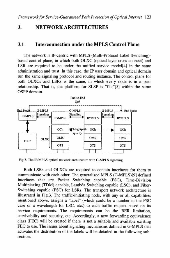
The network is IP-centric with MPLS (Multi-Protocol Label Switching)based control plane, in which both OLXC (optical layer cross connect) and LSR are required to be under the unified service model[4] in the same administration and trust. In this case, the IP user domain and optical domain run the same signaling protocol and routing instance. The control plane for both OLXCs and LSRs is the same, in which every node is in a peer relationship. That is, the platform for SLSP is "flat"[5] within the same OSPF domain.
End-to-End QoS
r-------------------------------------------, I I
Ene! Norl'r G-MPLS G-MPLS G-MPLS • End
IPIMPLS Signaling
I IP/MPLS IPIMPLS IPIMPLS
-" OCh th ..... Oc.h ......... ...............• OCh
quality
OMS OMS OMS DXC
OTS OTS OTS
J L I L I
Fig.3. The IP/MPLS optical network architecture with G-MPLS signaling.
ode
Both LSRs and OLXCs are required to contain interfaces for them to communicate with each other. The generalized MPLS (G-MPLS)[9] defined interfaces that are Packet Switching capable (PSC), Time-Division Multiplexing (TDM) capable, Lambda Switching capable (LSC), and FiberSwitching capable (FSC) for LSRs. The transport network architecture is illustrated in Fig.3. The traffic-initiating node, with any or all capabilities mentioned above, assigns a "label" (which could be a number in the PSC case or a wavelength for LSC, etc.) to each traffic request based on its service requirements. The requirements can be the BER limitation, survivability and security, etc. Accordingly, a new forwarding equivalence class (FEC) will be created if there is not a suitable and available existing FEC to use. The issues about signaling mechanisms defined in G-MPLS that activates the distribution of the labels will be detailed in the following subsection.

124 Pin-Han Ho and H T Mouftah
Because of the adoption of the MPLS-based control plane, the QoSaware layer mentioned in [19] is no longer needed. The FEe mapping and label assignment have well performed the function of class of service for each traffic flow.
3.2 Functional Architecture of Network Nodes
The functional diagram of oxes and LSRs are shown in FigA. The IPIMPLS control box is configured with the MPLS control plane functions for both oxe and LSR. The transport layers for oxe and LSR are optical layer cross connect (OLXC) and digital cross connect (DXC) respectively, which are controlled by their IPIMPLS control boxes. There are three main functions provided by the IPIMPLS control box.
IGP route CSPF path [P/MPLS control box
LSP election election se up
Link state SP etup
database
Information .:r nooding IS-IS/OSPF routing
DXClOLXC '-_______________ ---J Flows out
Fig.4: The functional architectures for oxe and LSR
First, the constrained shortest path first (CSPF) path selection module can calculate both work and protection paths upon different constraints such as reservable bandwidth of a link, wavelength availability, and diversity requirement, according to the TE (traffic engineering) database and SRLG information. Second, the extended RSVP or CR-LDP[6, 7] signaling component will be activated to send a Path Message to setup up a path based on the calculation result from the CSPF path selection. Besides, it can also respond to the requests from the other nodes in the network for establishing connections. Third, there is an ISISIOSPF routing protocol module with ISIS/OSPF optical and TE extensions[8] for disseminating link states and TE metrics, so that the other nodes in the domain can verify/update the information in their link state and Traffic engineering (TE) database. All the signaling mechanisms specifically for the optical networking environment have been included into the G-MPLS, which summarizes the optical and TE extensions from the MPLS protocol, and can handle inter-domain signaling
Framework/or Service-Guaranteed Path Protection o/Optical Internet 125
(i.e., between optical and user IP domains) and TE link states dissemination for the IP user and the optical domain.
4. SLSP DESCRIPTION
The new protection scheme, SLSP, is a scalable end-to-end serviceguaranteed shared protection scheme, which accommodates the characteristics of both path-based protection and link-based protection. It provides finer and more service granularities than the traditional shared protection schemes. The main idea of SLSP is to divide the protected working path into several overlapped segments, each of which is assigned by the first hop node a protection domain 10 (PID) at the routing stage, as shown in Fig.5. The calculation of the protection path for each protection domain can be done either by the first hop node alone, or decentralized to PSLs in each sub-domain, depending on how the SRLG information is configured in each node and how heavy workload the first hop node can afford at that time. With the CSPF path selection module, every node (LSR or OXC) is able to do a diverse routing within its protection domain. Although the decentralized selection of the protection paths lays down part of the burden of the first hop node, it may also subject to a problem that some of the PSLs fail to find qualified protection paths. How to determine which way to go is still under study.
Fig.5 illustrates how a path under SLSP is configured and recovered when a fault occurs. Node A is the first hop node and node N is the last hop node[2], which could respectively be the source node and the destination node of this path. The first protection domain (PID = 1) starts at node A and ends at node F. The second protection domain (PID = 2) is from node E to node J, and the third is from node I to node N. In this case, (A, F), (E, J) and (I, N) are the corresponding PSL-PML pairs for each of the protection domains.
Since each protection domain is overlapped with its neighboring protection domains by a link and two nodes, a single failure on any link or node along the path can be recovered. For example, a fault on link 4 or node E is localized by node D. A fault on link 5 or node F is localized by node E. In the former case, node 0 will send a FIS to notify node A that a fault occurred in their protection domain. In the later case, node E is itself a PSL. In each of the cases, the PSL (i.e. A or E) immediately sends a wake-up packet to activate the configuration of each node along the corresponding protection path, and then the traffic can be switched over to the protection path. A Tell-And-Go (TAG) [12] strategy can be adopted at this moment so that the PSL (i.e., node A or node E) may switch the traffic to the protection

126 Pin-Han Ho and H T Mouftah
path before an acknowledgement packet is received from the PML (i.e., node F or node I). At the completion of the switchover, the information associated with this reconfiguration has to be disseminated to all the other nodes. By doing this, the situation that the other traffic sources send best-effort traffic to these newly occupied resources.can be avoided.
Under the single-failure assumption, the other working paths that share the same protection resources are not supposed to be interrupted during the time when their protection paths are used by the switched working path. However, for the environment where mUltiple failures are considered, a working path has to possess two or more sets of partially or totally disjoint protection paths to prevent from the possibility that its protection resources are busy while it needs them.
When the fault on the working path is fixed and a switchback to the original working path is required, a packet for releasing the protection resources can be sent by the PSL right after the traffic is switched. With this, the protection resources can be reported as "free" again to all the other nodes.
PDIDI PDlD2 PDID3
Fig.S. SLSP protection scheme divides the working path into several overlapped protection domains. Node A, E, I are the PSLs, and node F, J, N are the PMLs.
To implement the protection information dissemination, the association of the protection resources in each sub-domain with corresponding working path segments (POID) has to be included in its forwarding adjacency (FA) [4]. The other working paths must know this association before they can reserve any piece of protection resources for protection use. An example is shown in Fig.5. wI and w2 possess the same SRLG on link 8. However, w2 can share all the protection resources of w I except those in the second protection domain (POID2). In addition, a signaling protocol, e.g. RSVP or CR-LOP, needs further extensions for the Path Message and Label Request Message to carry object to assign PSLs and PMLs for implementing SLSP.
The average restoration time and longest restoration time are two service indexes of interest for a path. The average restoration time will be

Framework/or Service-Guaranteed Path Protection o/Optical Internet 127
determined by averaging the restoration time of all the protection domains. The longest restoration time will depend on the size and node number of the largest protection domain along the path.
4.1 Inter-Domain Protection
Each of the ASON (automatically switched optical networks)[1O,18] and the ODS I (optical domain service interconnect)[1l,16,17], which is based on the viewpoint of a domain service model[4], has defined user-user interface (UN!) and/or network-network interface (NNI) to handle the inter-domain connection. Since the relationship between domains (In ASON, for both IPoptical and optical-optical domains; in ODS I only for IP-optical domain) is not treated as a peer, an end-to-end protection across UNIINNI is hard to be purely implemented in the optical layer. Instead, the layered approach will be adopted at the expense of the complex signaling mechanisms. According to the drafts associated with the two protocols, the promising candidates of interfacing carrier frame are SDH, Gigabit Ethernet and SONET, etc.[lO,1l,16,17,18], in which protection mechanisms has been well arranged.
For a pair of trusted domains, the inter-domain protection can be done with SLSP as shown in Fig.6, which would not differ from the situation where the working path is protected within a single domain.
_-->::.omain2
Fig.6. SLSP for inter-domain protection. The solid bold lines are for the working path, the dotted lines are for the inter-domain protection path. Nodes A are border routers, node B is a PSL, node C is a PML, and node D is an intennediate node within the protection domain.
5. ADVANTAGES OF SLSP
The advantages of SLSP framework over the ordinary path protection schemes are stated below. First, the complexity of calculating a diverse route under the constraint of whole domain's SRLG information can be segmented and largely diminished to several protection domains, in which the provisioning latency for dynamic path selection can be reduced. Second, since both notification and wake-up are performed on a very limited number of nodes, therefore, the restoration time is reduced according to the size of
128 Pin-Han Ho and HT Mouftah
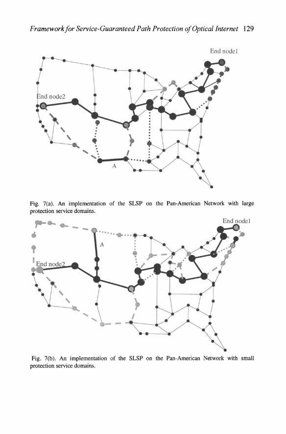
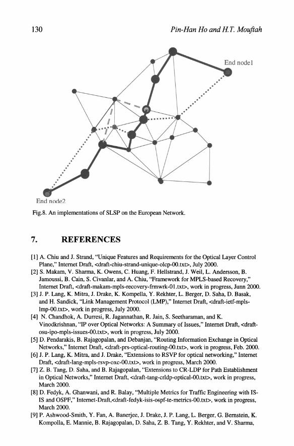
the protection domain. Third, the service is easier to be guaranteed since the restoration time does not vary with the length of the whole path, instead, the average size of the protection domains will be the dominant factor, which can be one of the items with which the service providers bill their customers. Fourth, SLSP can work well in any type of topologies. Examples are shown in Fig.7 and Fig.8. Fig.7. shows two implementations of SLSP on the PanAmerican Network. Fig.7(a) demonstrates the protection service with a longer recovery time than that in Fig.7(b) since the protection domains in Fig.7(a) are larger. The solid bold lines are for the working path, and the thick dash lines and dotted lines are for the inter-segmented protection paths.
It can also be applied to a path traversing several domains to achieve an end-to-end path protection as shown in Fig.6. Fifth, the computation complexity of protection domain allocation is simplified. The decentralized allocation scheme has largely decreased the computation efforts for the first hop node.
Compared with the pure link protection approach, SLSP provides flexibility in compromising restoration time and protection resources required, with which the class of service can be achieved with more granularities. The ISPs can put proper constraints on the path selection according to the SLA with each of their customers. The constraining parameters for the selection of protection path can be those related to the restoration time along the working path, such as the diameter of each protection domain and the physical distance between each PSL-PML pair, etc.
6. CONCLUSION
This paper proposed a new framework, SLSP, for end-to-end shared path protection, and qualitatively compared SLSP with the ordinary path-based and link-based shared protection schemes. In addition, the network service architecture and signaling mechanisms upon which SLSP can be implemented were demonstrated. SLSP can provide a wider spectrum of protection services with finer restoration granularities, which enhances the l:N and M:N shared protection in terms of scalability, restoration time and class of service. It will satisfy the versatile requirements of the multimedia applications and may be one of the best candidates strategies for ISPs to guarantee their services to the customers.
Framework/or Service-Guaranteed Path Protection o/Optical Internet 129
End nodel
Fig. 7(a). An implementation of the SLSP on the Pan-American Network with large protection service domains. ,.. .... .. ,
End node]
• ••• 111 111 •••• ____ . _
Fig. 7(b). An implementation of the SLSP on the Pan-American Network with small protection service domains.
130 Pin-Han Ho and H T Mouftah
. .
End node2
.' .. . . ,
, .
Fig.S. An implementations of SLSP on the European Network.
7. REFERENCES
,
. . , . . . , , .
. . . ,
[1] A. Chiu and 1. Strand, "Unique Features and Requirements for the Optical Layer Control Plane," Internet Draft, <draft-chiu-strand-unique-olcp-OO.txt>, July 2000.
[2] S. Makam, V. Sharma, K. Owens, C. Huang, F. Hellstrand, 1. Weil, L. Andersson, B. Jamoussi , B. Cain, S. Civanlar, and A. Chiu, "Framework for MPLS-based Recovery," Internet Draft, <draft-makam-mpls-recovery-frmwrk-Ol.txt>, work in progress, Junn 2000.
[3] J. P. Lang, K. Mitra, 1. Drake, K. Kompella, Y. Rekhter, L. Berger, D. Saba, D. Basak, and H. Sandick, "Link Management Protocol (LMP)," Internet Draft, <draft-ietf-mplsImp-OO.txt>, work in progress, July 2000.
[4] N. Chandhok, A. Durresi, R. Jagannathan, R. Jain, S. Seetharaman, and K. Vinodkrishnan, "IP over Optical Networks: A Summary of Issues," Internet Draft, <draftosu-ipo-mpls-issues-OO.txt>, work in progress, July 2000.
[5] D. Pendarakis, B. Rajagopalan, and Debanjan, "Routing Information Exchange in Optical Networks," Internet Draft, <draft-prs-optical-routing-OO.txt>, work in progress, Feb. 2000.
[6] J. P. Lang, K. Mitra, and J. Drake, "Extensions to RSVP for optical networking," Internet Draft, <draft-lang-mpls-rsvp-oxc-OO.txt>, work in progress, March 2000.
[7] Z. B. Tang, D. Saba, and B. Rajagopalan, "Extensions to CR-LDP for Path Establishment in Optical Networks," Internet Draft, <draft-tang-crldp-optical-OO.txt>, work in progress, March 2000.
[S] D. Fedyk, A. Ghanwani, and R. Balay, "Multiple Metrics for Traffic Engineering with ISIS and OSPF," Internet-Draft,<draft-fedyk-isis-ospf-te-metrics-OO.txt>, work in progress, March 2000.
[9] P. Ashwood-Smith, Y. Fan, A. Banerjee, 1. Drake, 1. P. Lang, L. Berger, G. Bernstein, K. Kompolla, E. Mannie, B. Rajagopalan, D. Saba, Z. B. Tang, Y. Rekhter, and V. Sharma,

Framework/or Service-Guaranteed Path Protection a/Optical Internet 131
"Generalized MPLS - Signaling Functional Description," Internet Draft, <draft-ash woodgeneralized-mpls-signaling-OO.txt>, work in progress, June 2000.
[10] M. Mayer, "First Draft of G.ason," Contribution to Tl Standards Project, March 2000. [11] G. Bernstein, 1.Weiss, R. Coltun, 1. moy, A. Sodder, and K. Arvind, "Optical Domain
Service Interconnect (ODS I) Functional Specification," ODSI Documents, Aug. 2000. [12] C. Qiao, "A High Speed Protocol for Bursty Traffic in Optical Networks," SPIE's All
Optical Communication Systems, vol. 3230, Nov. 1997. [13] Rajiv Ramaswarni, Kumar N. Sivarajan, "Optical Networks - A Practical Perspective",
Morgan Kaufmann Publishers, Inc, 1998. [14] D. O. Awduche, Y. Rekhter, J. Drake, and R. Coltun, "Multi-Protocol Lambda
Switching: Combining MPLS Traffic Engineering Control with Optical Crossconnects," Internet-Draft, < draft-awduche-mpls-te-optical-02.txt>, work in progress, July 2000.
[15] K. Owens, V. Sharma, and M. Ommen, "Network Survivability Considerations for Traffic Engineering IP Networks," Internet Draft, <draft-owens-te-network- survivabilityOO.txt>, work in progress, March 2000.
[16] S. Chaudhuri, G. Hjalmtysson, and J. Yates, "Control of Lightpaths in an Optical Network," Internet Draft, <draft- chaudhuri-ip-olxc-control-OO.txt>, Feb. 2000.
[17] O. Duroyon, E. Hoebeke, and H. D. Neve, ''Triggering and advertising lightpaths in an IP over optical network," Internet Draft, <draft-duroyon-te-ip-optical-OO.txt>, work in progress, July 2000.
[18] S. J. Chen, "ASON - the UNI and its Computational Model," Contribution to Tl Standards Project--TlX1.5, July 2000.
[19] T. D. N. Nada Golrnie, David H. Su, "A Differentiated Optical Services Model for WDM Networks," IEEE Communication Magazine, vol. 38, pp. 68-73, Feb. 2000.


![Open Shortest Path First Routing Under Random Early Detectionsd-research.uwaterloo.ca/papers/Networks-OSPF-Routing-with-RED.pdf · First (OSPF) routing protocol [35], where OSPF requires](https://static.fdocuments.us/doc/165x107/5f746308e2e9e43294254a6e/open-shortest-path-first-routing-under-random-early-detectionsd-first-ospf-routing.jpg)