
A Framework for Modeling and Analyzing Fault-Tolerance · A Framework for Modeling and Analyzing...
43
A Framework for Modeling and Analyzing Fault-Tolerance 1 Ali Ebnenasir Betty H.C. Cheng Software Engineering and Network Systems Laboratory Department of Computer Science and Engineering Michigan State University East Lansing MI 48824 USA Abstract The development of fault-tolerant systems continues to be difficult due to the evolving and crosscutting nature of fault-tolerance requirements. Fault-tolerance research has largely focused on how to design and implement fault-tolerant systems. Regardless of how fault-tolerance is provided, however, it is equally important to determine what constraints should be met both in the absence and in the presence of faults. In order to address this question, this paper describes a systematic method for modeling and analyzing fault-tolerance concerns in UML at the re- quirements analysis phase. First, we present an approach for use case analysis of fault-tolerance requirements based on two canonical families of constraints, namely detection and correction constraints. Second, we present a method for object analysis of fault-tolerance requirements where we refine our use case analysis model using two object analysis patterns, called detector and corrector patterns. These detector and corrector object analysis patterns are based on the formal definition of detector and corrector components, which have been proven to be necessary and sufficient for the design of fault-tolerance. Finally, we define an Object Computation Model to provide a formal semantics for our fault-tolerance object analysis patterns. The Object Com- putation Model can be instantiated to different target specification languages using previously developed UML formalization framework, Hydra. As a result, we are able to automatically generate formal specification for the UML diagrams comprising the composition of functional and fault-tolerance requirements, thus enabling the automated analysis of fault-tolerance. We demonstrate our analysis method in the context of an industrial automotive application. Keywords: Requirements Analysis, Fault-Tolerance, Formal Methods Detectors, Correctors 1 Email: [email protected], [email protected] Web: http://www.cse.msu.edu/ ∼ {ebnenasi,chengb} Tel: +1-517-355-2387, Fax: +1-517-432-1061 This work was partially sponsored by NSF grants EIA-0000433, CDA-9700732, CCR-9901017, and a grant from Michigan State University. 1
Transcript of A Framework for Modeling and Analyzing Fault-Tolerance · A Framework for Modeling and Analyzing...
A Framework for Modeling and Analyzing
Fault-Tolerance1
Ali Ebnenasir Betty H.C. ChengSoftware Engineering and Network Systems Laboratory
Department of Computer Science and EngineeringMichigan State University
East Lansing MI 48824 USA
Abstract
The development of fault-tolerant systems continues to be difficult due to the evolving andcrosscutting nature of fault-tolerance requirements. Fault-tolerance research has largely focusedon how to design and implement fault-tolerant systems. Regardless of how fault-tolerance isprovided, however, it is equally important to determine what constraints should be met both inthe absence and in the presence of faults. In order to address this question, this paper describesa systematic method for modeling and analyzing fault-tolerance concerns in UML at the re-quirements analysis phase. First, we present an approach for use case analysis of fault-tolerancerequirements based on two canonical families of constraints, namely detection and correctionconstraints. Second, we present a method for object analysis of fault-tolerance requirementswhere we refine our use case analysis model using two object analysis patterns, called detectorand corrector patterns. These detector and corrector object analysis patterns are based on theformal definition of detector and corrector components, which have been proven to be necessaryand sufficient for the design of fault-tolerance. Finally, we define an Object Computation Modelto provide a formal semantics for our fault-tolerance object analysis patterns. The Object Com-putation Model can be instantiated to different target specification languages using previouslydeveloped UML formalization framework, Hydra. As a result, we are able to automaticallygenerate formal specification for the UML diagrams comprising the composition of functionaland fault-tolerance requirements, thus enabling the automated analysis of fault-tolerance. Wedemonstrate our analysis method in the context of an industrial automotive application.
Keywords: Requirements Analysis, Fault-Tolerance, Formal MethodsDetectors, Correctors
1Email: [email protected], [email protected]: http://www.cse.msu.edu/∼{ebnenasi,chengb}Tel: +1-517-355-2387, Fax: +1-517-432-1061This work was partially sponsored by NSF grants EIA-0000433, CDA-9700732, CCR-9901017, and
a grant from Michigan State University.
1
1 Introduction
The complexity of developing fault-tolerant systems is due to (i) the crosscutting and evolvingnature of fault-tolerance requirements, and (ii) the fact that user requirements should be metboth in the absence and in the presence of faults. To deal with this complexity, more work isneeded to analyze the consistency of functional and fault-tolerance requirements in order to preventthe propagation of logical inconsistencies from the requirements to the design and coding phases.Towards this end, this paper presents a method for implementation-independent modeling andanalysis of fault-tolerance requirements.
Numerous approaches exist for designing fault-tolerant systems [1–8], most of which focus on imple-mentation constraints to support fault-tolerance. For example, Randall’s seminal work [1] focuseson the use of recovery blocks in the implementation of fault-tolerant software systems. Also, incheckpointing and log-based recovery mechanisms [6], the fault-tolerant system first saves the stateof the system computations (i.e., checkpointing), and then recovers to a legitimate state once anerror state is detected. Schneider [4] presents a mechanism for the design of replicated servers ina client-server model. In such a replication-based approach, a deterministic replica managementprotocol coordinates the execution of the replicated server. All of these approaches have a commonfocus on the design of fault-tolerance against specific types of faults (e.g., fail-stop faults [4,6]) andfor particular architectures (e.g., client-server [4]). While fault-tolerance should eventually be con-sidered at design time, we believe that, regardless of how fault-tolerance is implemented, developersshould first consider what constraints a fault-tolerant system should meet, both in the presence andin the absence of faults. Such an emphasis on the analysis of fault-tolerance concerns preventsthe propagation of inconsistencies of functional and fault-tolerance requirements to the design andcoding phases. For example, in the development of a distributed database management systemthat is expected to be fault-tolerant against crash faults, restoring the state of the database after anode crashes may be inconsistent with preserving the integrity of the database during restoration.
We introduce a method for modeling and analyzing faults and fault-tolerance in UML at therequirements analysis level. Our approach separates functional and fault-tolerance concerns. Westart with a valid model of a system (i.e., fault-intolerant system model) that meets its requirementsin the absence of faults. Then we extend the fault-intolerant model by modeling faults and fault-tolerance requirements. Our approach comprises three main steps. First, we perform a use casebased analysis of faults and error detection and correction. Second, we apply our newly developedfault-tolerance analysis patterns for error detection and correction towards creating UML classand state (respectively, sequence) diagrams for fault-tolerant systems. Finally, we generate formalspecifications from the UML diagrams using the formal semantics of the fault-tolerance analysispatterns, and a previously developed semantics for the UML diagrams [9, 10].
Our method comprises the analysis of faults and fault-tolerance requirements at the use case leveland at the object analysis level. Specifically, we extend the fault-intolerant use case model by mod-eling (i) faults as actors that may temporarily change the behavior of the system; (ii) the effect offaults as faulty use cases, and (iii) fault-tolerance requirements as a set of detection and correctionconstraints that must be met in the absence and in the presence of faults. We also model use casesthat detect (respectively, correct) corresponding detection (respectively, correction) constraints. Atthe object analysis level, we use the notion of state perturbation to model faults. State pertur-bation has been used in previous work [11–13] for modeling different types of faults with different
2

behavioral natures. In addition to modeling faults, we extend the notion of detector and correctorcomponents from [14, 15] to develop detector and corrector patterns for modeling fault-tolerancerequirements. Arora and Kulkarni [14, 15] have shown that detectors and correctors are necessaryand sufficient for specifying fault-tolerance requirements. As such, detector and corrector patternsserve to modularize fault-tolerance requirements. Such modularization helps system modelers inreasoning about fault-tolerance, and in tracing the fault-tolerance concerns at different stages ofthe software lifecycle. Note that, in this paper, detector and corrector patterns provide a system-atic approach for refining fault-tolerance requirements instead of providing patterns for designinga system. To provide a framework for automated analysis, we introduce a formal semantics forthe object analysis of UML models. Our formal semantics provides an Object Computation Model(OCM) for object-oriented models in UML that can be translated to different target specifica-tion languages. In particular, we generate the specification of the fault-tolerant UML models inPromela [16]. Such formalization enables the automatic analysis of fault-tolerant systems, wherewe create a formal model of the fault-tolerant system and use model checkers (e.g., SPIN [17]) andsynthesis tools (e.g., [18]) for reasoning about fault-tolerance requirements.
We demonstrate our analysis method in the modeling of an adaptive cruise control (ACC) systemin UML. Specifically, we illustrate how we model faults and how we specify detection and correctionconstraints to generate a fault-tolerant use case model of the ACC system. Subsequently, we refinethe use case model of the ACC system using detector and corrector patterns. Using our approach,developers can model fault types that would be difficult (if not impossible) to model using existingapproaches [8, 19, 20]. For example, transient faults may perturb the state of a buffer and causetemporary buffer overflow that is difficult to model using the notion of component failure discussedin [8,19]. Further, the notion of fault-tolerance in the existing approaches is mostly based on usingreplication to mask faults (i.e., masking fault-tolerance); less emphasis has been put on other formsof fault-tolerance (e.g., failsafe fault-tolerance [21] and self-stabilization [11]). We illustrate how tomodel such levels of fault-tolerance using our approach. The remainder of this paper is organizedas follows. Section 2 presents preliminary concepts, where we introduce the Object ComputationModel for UML models. Section 3 illustrates modeling of faults and fault-tolerance at the use caselevel in UML. Section 4 demonstrates how we model faults in UML object models. Sections 5 and6 respectively present the detector and corrector patterns that are applied for solving detectionand correction constraints at the object analysis level. Section 7 presents a translation of detectorand corrector patterns from OCM to the Promela modeling language. Such a formalization enablesanalysts to use the model checker SPIN [17] for verifying the interference-freedom of functionaland fault-tolerance concerns; i.e., the detection/correction constraints and functional requirementsare met in the presence of each other. Section 8 summarizes the requirements analysis methodpresented in this paper. Section 9 illustrate the proposed analysis method in the context of aDiesel Filter System. Section 10 discusses and compares related work. Finally, Section 11 givesconcluding remarks and discusses future work.
2 Preliminaries
In this section, we present basic concepts of (i) UML models; (ii) our formal representation ofobject-oriented systems in UML, and (iii) the definition of faults and fault-tolerance.
3

2.1 UML
The Unified Modeling Language (UML) [22] provides visual artifacts for system specification.Specifically, UML presents a visual language for requirements elicitation, and structural and be-havioral system specification. To obtain user requirements, UML has adopted Jacobson’s notionof use cases [23]. A use case specifies scenarios of using the subject system which represent usergoals for the system. At the design level, UML comprises a set of diagrams for representing thestructure and the behavior of a system. At the structural design level, modelers use class, object,and package diagrams to represent the structure of a system and its components. At the behavioraldesign level, UML provides state and sequence diagrams for representing system behaviors.
In order to enable formal analysis (e.g., model checking) of UML models, it is necessary to haveformal specification of the UML models. There exist approaches for generating domain-specificformal specification from UML models. For example, McUmber and Cheng [9] present a methodfor automatic transformation of UML behavioral models to Promela [16] for requirements analysisof embedded systems. We extend McUmber and Cheng’s technique to generate formal specificationof the UML models of fault-tolerant systems in Promela (see Section 7), which enables us to usethe SPIN model checker simulation environment.
We use a subset of UML in modeling and specifying fault-tolerant systems. More specifically, weuse UML artifacts for use case analysis of fault-tolerant systems, where we model faults and fault-tolerance requirements at the use case level. As we refine our use case model, we use the UMLsubset for object modeling and analysis towards creating the object analysis model of fault-tolerantsystems.
2.2 Object Computation Model
In this section, we represent the Object Computation Model (OCM) that we have developed (in [24])to provide a computational semantics for object-oriented models in UML. Each object2 consists ofa set of state variables (with finite domains) and a set of methods (i.e., actions). A state of anobject is a valuation to its state variables. (The threads of control of an object can be consideredas state variables as well.) The finite state space of an object O, denoted SO, is the set of allstates of that object. An OCM M is a triple 〈O, T ,P〉, where O is a set of objects O1, · · · , Ok
(1 ≤ i ≤ k), T is a relation that represents the interconnection of the objects in O, and P is a setof state predicates. A state predicate, X, is any subset of SM = SO1 × SO2 × · · · × SOk
, where SOi
is the state space of Oi (1 ≤ i ≤ k). A global state of M is a k-tuple in SM. The state space SM ofM comprises all global states. We define the set of methods of an object Oi by a set of transitionsδOi ⊆ SM × SM (1 ≤ i ≤ k). A computation of an OCM M is an infinite sequence 〈s0, s1, · · ·〉 ofglobal states in which each transition (sj , sj+1) (0 ≤ j) belongs to some object Oi (1 ≤ i ≤ k). Eachcomputation is maximal; i.e., if it is finite then the last state represents a valid halting scenario ofthe system model. If the requirements allow a finite computation c = 〈s0, s1, · · · , s〉 to be extendedto an infinite sequence by including the transition (s, s) in the set of transitions of M, then c is ahalting computation. Otherwise, c is a deadlock computation and s is a deadlock state; i.e., a statewith no outgoing transitions.
Encapsulation model. The encapsulation of methods and state variables of objects imposes a2An object is a behavioral representation of a class.
4
set of read/write restrictions on each object. An object is allowed to read/write all its private andpublic variables. Although an object cannot read/write private variables of other objects, it maybe able to read/write the public variables of other objects. The set of variables that are readablefor an object determines the locality of that object. A local state predicate represents a set of globalstates in the locality of an object. A global state predicate consists of a set of global states of anOCM M.
Object association model. In the analysis of fault-tolerant systems, we focus on the essenceof inter-object communications rather than the type of inter-object associations (e.g., inheritance,aggregation, etc.). Hence, at the OCM level, we abstract out the semantics of inter-object associ-ations (e.g., inheritance, aggregation, etc.) specified at the UML level. For example, if an objectA inherits its behaviors from another object B then at the OCM level, the relations of A with Band other objects are modeled in the context of the variables of B that A is allowed to read/writeand vice versa. The fact that object A inherits the behaviors of B has less effect on the results ofanalyzing fault-tolerance concerns. While there exist formal methods [25] and refinement mappingtechniques [26–28] for capturing inheritance in an object-oriented system, we abstract out the typeof inter-object associations in OCM.
The complexity of analyzing fault-tolerance requirements could vary from polynomial to unde-cidable [21, 29, 30], depending on the computational model. We have adopted a shared memory(interleaving) model (i.e., OCM) for the analysis of fault-tolerance requirements to reduce the com-plexity of automated analysis of fault-tolerance requirements. Sound techniques [26, 28, 31] can beused to refine the fault-tolerant conceptual model of a system from OCM to a message-passingmodel.
2.3 Properties of Interest
In this section, we formally define functional requirements in OCM. We focus on the set of userrequirements that can be classified in terms of two categories of safety and liveness requirements [32].Subsequently, we define what it means for an OCM to meet its safety and liveness requirements.
We formally represent the functional requirements as a set R of sequences 〈s0, s1, · · ·〉 of globalstates in OCM. In an OCM M, the set of functional requirements R is an intersection of the safetyand liveness requirements. A safety requirement stipulates that nothing bad will ever happen. Forexample, if the objects in an OCM M share a critical section then the safety of the model isviolated if more than one object enters the critical section simultaneously. We follow Alpern andSchneider [32] where we represent the safety requirements of an OCM M as a set of finite sequenceof transitions 〈s0, · · · , sn〉 that must not be executed by M; i.e., a set of bad sequences. Intuitively,a liveness requirement specifies that something good will eventually happen. We represent theliveness requirements as a set of infinite sequences 〈s0, s1, · · ·〉 of states, where each sequence inthe set has a suffix that is in the liveness requirements. For example, in reactive systems3, leads-to properties [33] are often used to specify the liveness requirements, where a leads-to propertystipulates that the system will eventually respond to the stimuli of its environment.
The validation of an OCM M depends on the validation of the computations of M. A computationc of an OCM M validates the safety and liveness requirements iff (if and only if) c ∈ R. The OCMmodel M validates the safety and liveness requirements iff all its computations validate the safety
3Reactive systems have non-terminating behaviors and always react to the stimuli of their environment (e.g.,network protocols, controlling software of embedded systems).
5

and liveness requirements. A computation c violates safety requirements (i.e., c is a safety-invalidcomputation) if c includes a sequence of transitions that is ruled out by the safety requirements;i.e., includes a bad sequence. A computation c violates liveness requirements (i.e., c is a liveness-invalid computation) if c includes (i) a deadlock state, or (ii) a non-progress cycle of transitions inwhich nothing good ever happens. An OCM M is invalid with respect to its safety requirements iff Mincludes a safety-invalid computation. An OCM M is invalid with respect to its liveness requirementsiff M includes a liveness-invalid computation. An OCM M is valid iff M includes no safety-invalidand no liveness-invalid computations. An invariant IM for an OCM M is a non-empty global statepredicate such that all computations starting in IM validate the safety and liveness requirements.
2.4 Behavioral Association of UML and OCM
In this section, we define the underlying semantics of UML behavioral models in OCM. Specifically,for an UML model M and its corresponding OCM M, a state in an UML state transition diagramrepresents a state predicate in SM (i.e., a mode of operation of an object O). Each transitionin an UML state diagram represents a set of transitions in SM × SM in the underlying OCMM. A sequence diagram in M captures an equivalence class of computations in the correspondingOCM M that represents a requirements scenario. A deadlocked sequence diagram (i.e., deadlockscenario) represents a set of deadlocked computations in the corresponding OCM M. An invalidscenario represents a set of invalid computations of the corresponding OCM M. Thus, a safety-invalid sequence diagram represents a scenario that violates the safety requirements. Likewise, aliveness-invalid sequence diagram represents a scenario that violates the liveness requirements.
2.5 Faults and Fault-Tolerance
In this section, we illustrate how we formally represent faults in OCM. Also, we define three levels offault-tolerance requirements based on the extent up to which a system meets its safety and livenessrequirements in the presence of faults.
In an OCM M, we represent a fault-type f as a set of transitions in the entire state space of M4.In other words, faults f are transitions that perturb the state of a system in an uncontrollablemanner; i.e., the system does not have execution control over fault transitions. Such a notion ofstate perturbation is expressive enough to represent different types of faults (e.g., stuck-at, crash,fail-stop, omission, Byzantine, and design flaws) with different behavioral natures (i.e., transient,intermittent, and permanent) [11–13]. A computation of an OCM M in the presence of faults f isa maximal sequence 〈s0, s1, · · ·〉 of global states that satisfies the following conditions: (1) everytransition (sj , sj+1), where 0 ≤ j, belongs either to f or to one of the objects in M, and (2)the number of fault occurrences in that computation is finite. The latter requirement is the sameas that made in previous work [11, 12, 34, 35] to ensure that eventually recovery can occur. Theboundary up to which the state of M could be perturbed by fault f is called the f -span (i.e., fault-span) of M. For an OCM M, we represent its fault-span by a state predicate that is a supersetof its invariant IM. Next, we extend the definition of three levels of fault-tolerance from [13,30] inOCM. The definition of these three levels of fault-tolerance is based on the extent up to which user
4We follow the approach of [13] in modeling faults as a set of transitions that are triggered non-deterministically.
6

requirements are met in the presence of faults.
Failsafe fault-tolerance. Intuitively, failsafe fault-tolerance requires that nothing bad everhappens even in the presence of faults. An OCM M is failsafe f -tolerant (i.e., fault-tolerant forfault-type f) from IM iff starting from IM (1) in the absence of faults f , M validates its safetyand liveness requirements, and (2) in the presence of faults f , M guarantees to validate its safetyrequirements.
Nonmasking fault-tolerance. Nonmasking fault-tolerance requires that recovery to the invariantis provided if faults perturb the state of a system outside its invariant. An OCM M is nonmaskingf -tolerant from IM iff starting from IM (1) in the absence of faults f , M validates its safety andliveness requirements, and (2) in the presence of faults f , every computation of M that starts inf -span of M will eventually reach a state in IM.
A special case of nonmasking fault-tolerance where the fault-span is equal to the entire state spaceis called self-stabilization. A system is self-stabilizing if it eventually recovers to its invariant fromevery state in its state space [11]. Self-stabilization has important applications in the developmentof resilient network protocols that survive in the presence of transient faults; i.e., faults that occurspontaneously and then disappear. This paper does not specifically focus on self-stabilization,nonetheless, the techniques used for the analysis of nonmasking fault-tolerance can be applied inthe analysis of self-stabilizing systems.
Masking fault-tolerance. Masking fault-tolerance requires that (i) nothing bad will ever happen,and (ii) recovery to the invariant is guaranteed if faults perturb the state of a system outside itsinvariant. An OCM M is masking f -tolerant from IM iff starting from IM (1) in the absence offaults f , M validates its safety and liveness requirements; (2) in the presence of faults f , (a) everycomputation of M that starts in the f -span of M will eventually reach a state in IM, and (b) nocomputation of M that starts in the f -span of M violates the safety requirements.
Notation. Whenever the OCM M is clear from the context, we will omit it; thus, “M is fail-safe (respectively, nonmasking or masking) f -tolerant” abbreviates “M is failsafe (respectively,nonmasking or masking) f -tolerant from IM”.
3 Use Case Analysis of Fault-Tolerant Systems
In this section, we present our method for specifying faults and fault-tolerance requirements at theuse case analysis level. First, we illustrate how to model faults, the impact of faults on a system,and fault-tolerance requirements. Then we demonstrate our approach in the context of an adaptivecruise control (ACC) system. We use the ACC system as a running example in the rest of thepaper.
In use case analysis of fault-tolerant systems, we separate the use case modeling of functionalrequirements from the modeling of fault-tolerance requirements. Specifically, we assume that theinput to our analysis method is the use case model of the fault-intolerant system that has beenvalidated with respect to functional user requirements. In addition to the regular use cases, thefault-intolerant use case model should include (i) a set of misuse cases [36], and (ii) a globalinvariant constraint (see Figure 1). A misuse case specifies behaviors that must never appearin the set of system functionalities. We use misuse cases to specify the safety requirements ofthe fault-intolerant system model; i.e., bad things that must never happen. Such a method of
7
modeling safety requirements using misuse cases can also be found in previous work [37] (see usecases with inverted colors in Figure 1). The invariant specifies a global constraint that the systemsatisfies in the absence of faults; i.e., if the invariant constraint holds then the user requirementswill be met. If the invariant does not hold then there will be no guarantees that the systemwill meet its requirements. Therefore, depending on the problem at hand, the analysts and thesystem users should collaborate in specifying a global invariant constraint before modeling fault-tolerance requirements. The specification of the invariant constraint simplifies reasoning about thebehavior of fault-tolerant systems. Although identifying an invariant constraint is not an easy task,there exist systematic (and automatic) approaches for generating invariant constraints from userrequirements [38,39].
Specifying faults and their impact on the subject system. We model faults as actors andmodel the impact of faults on the system as faulty use cases. A fault-type (e.g., fail-stop, crash,and Byzantine) is a type of event that temporarily takes the control of the system execution. Inother words, a system that is subject to faults does not have control over the occurrence of faults.Thus, each fault-type can be considered as a logical entity whose goal is to perturb the state ofthe system. Hence, we model each type of faults as an actor whose actions may not be necessarilytowards the system goals (see the filled-head actor in Figure 1). Also, we model the effect offaults on the system as faulty use cases (see the shadowed use case in Figure 1). A faulty use caserepresents a set of behaviors exhibited by the system due to the actions of a fault actor that mayor may not result in the violation of (safety and liveness) requirements. A faulty use case may be amisuse case, thus directly leading to the violation of the safety requirements. Also, a faulty use casemay perturb the system outside its invariant from where the system itself may exhibit a misusecase and indirectly violate the safety requirements. Furthermore, when a faulty use case perturbsthe state of the system outside the invariant, the system may either (i) deadlock, or (ii) trap in anon-progress cycle.
Specifying fault-tolerance. In order to specify fault-tolerance at the use case level, we identifytwo canonical families of constraints, namely detection and correction constraints, that must be metboth in the presence and in the absence of faults. Such constraints (i) separate fault-tolerancerequirements from functional requirements, and (ii) provide traceability from use case level to theobject analysis level and further to design and coding.
We use detection constraints to model failsafe fault-tolerance. A failsafe fault-tolerant system mustnot execute any misuse cases even in the presence of faults. Thus, if there exist any behavioralsimilarities5 between the set of misuse cases and a faulty use case UCf then the analysts shouldidentify the conditions under which UCf executes. Such conditions represent constraints that thesystem should detect (see Figure 1) to prevent the violation of safety requirements. Note that thesystem cannot prevent the occurrence of faults, however, the system can control the preconditionsthat lead to the occurrence of faults. The detection constraints model such preconditions.
We use correction constraints to model nonmasking fault-tolerance. If faults perturb the systemoutside its invariant then there will be no guarantees that the system will meet its requirements.Thus, to provide nonmasking fault-tolerance (i.e., recovery in the presence of faults), we needto identify conditions under which the invariant constraint will eventually hold. We model suchconditions as correction constraints. The correction constraints specify postconditions that should
5Previous work [40–42] provides techniques for behavioral specification of use cases that can be used for checkingbehavioral similarities.
8

System
**
«invariant»
{Universal Constraint }
MisuseCase_1
UseCase_1 UseCase_2 UseCase_N. . .
Use Cases
MisuseCase_2 MisuseCase_M. . .
«precondition»
{CNSTRT_1} CNSTRT_1 is the precondition
for the activation of MisuseCase1
in the presence of F
DetectCNSTRT_1
«precondition»
{CNSTRT_M}DetectCNSTRT_M
CorrectCNSTRT'_1
CorrectCNSTRT'_M
«postcondition»
{CNSTRT'_1} CNSTRT'_1 is the postcondition
that must hold after the
detection of CNSTRT_1
«postcondition»
{CNSTRT'_M}
.
.
.
Fault Impact
Fault
Figure 1: Use case diagram.
hold after the occurrence of faults. Note that the only requirement of nonmasking fault-toleranceis recovery, and the safety requirements may be violated during recovery.
We use both detection and correction constraints to model masking fault-tolerance. Since a maskingfault-tolerant system should simultaneously guarantee safety and recovery, we use (1) correctionconstraints to model recovery to the invariant, and (2) detection constraints to model safety in thepresence of faults. Therefore, the specification of masking fault-tolerance at the use case level isindeed the conjunction of specifying failsafe and nonmasking fault-tolerance simultaneously.
Comment on the complexity of identifying detection and correction constraints. Detection andcorrection are problems that should be modeled and specified during the analysis of fault-tolerancerequirements. It is the responsibility of all stake holders to specify detection and correction con-straints together. We believe that analysts should provide abstract and platform-independentsolutions for specifying detection and correction constraints, while users provide domain knowledgeto customize the specification of such constraints. As a result, it will be feasible to investigatepotential inconsistencies between satisfying detection and correction constraints and satisfying sys-tem functionalities. While the identification of detection and correction constraints may prolongthe requirements analysis phase, we believe that it is worth to analyze fault-tolerance requirementsat the early stages of the software lifecycle instead of paying a higher cost in the design and im-
9
plementation phases for resolving the potential inconsistencies of functional and fault-tolerancerequirements. In Sections 5 and 6, we respectively present detector and corrector analysis patternsthat provide a strategy for specifying detection and correction constraints (i.e., fault-tolerance re-quirements) at the object analysis level. Next, we demonstrate our use case analysis method foran adaptive cruise control system.
3.1 Case Study: Adaptive Cruise Control
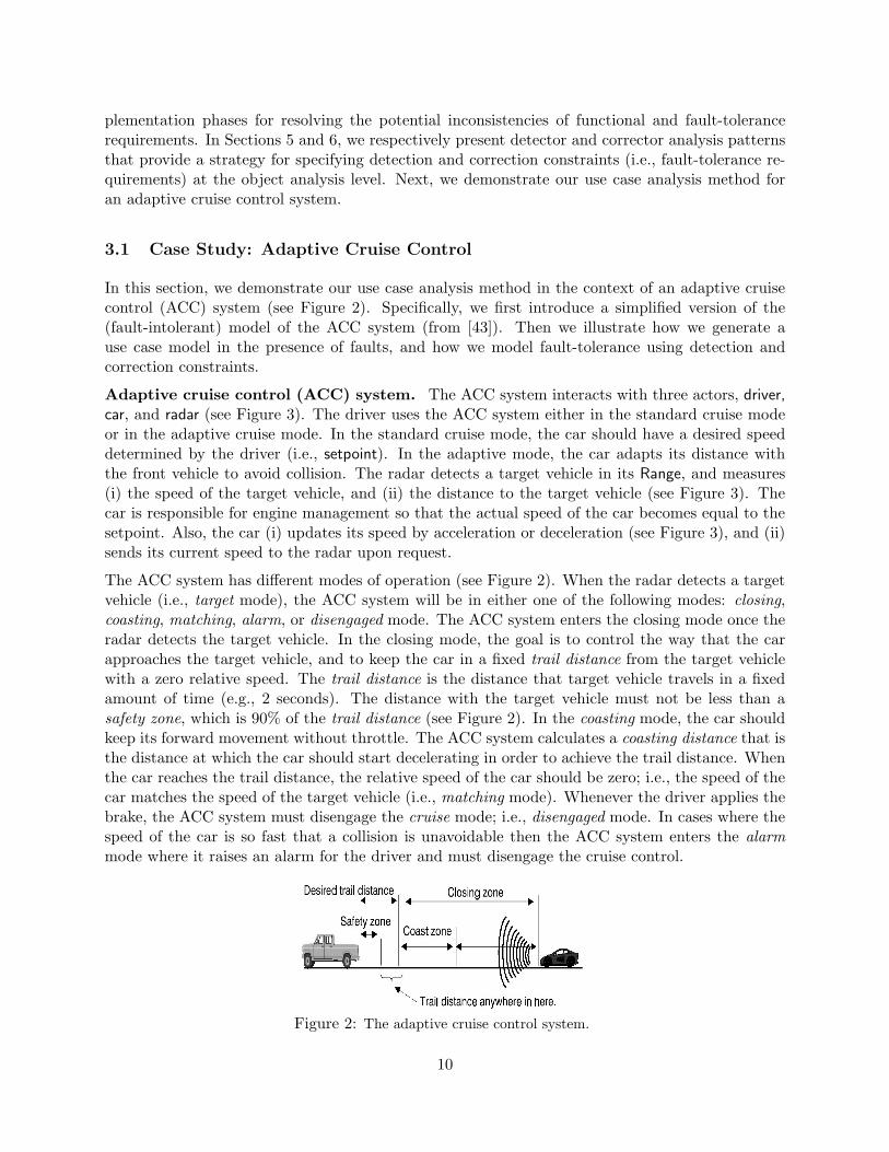
In this section, we demonstrate our use case analysis method in the context of an adaptive cruisecontrol (ACC) system (see Figure 2). Specifically, we first introduce a simplified version of the(fault-intolerant) model of the ACC system (from [43]). Then we illustrate how we generate ause case model in the presence of faults, and how we model fault-tolerance using detection andcorrection constraints.
Adaptive cruise control (ACC) system. The ACC system interacts with three actors, driver,car, and radar (see Figure 3). The driver uses the ACC system either in the standard cruise modeor in the adaptive cruise mode. In the standard cruise mode, the car should have a desired speeddetermined by the driver (i.e., setpoint). In the adaptive mode, the car adapts its distance withthe front vehicle to avoid collision. The radar detects a target vehicle in its Range, and measures(i) the speed of the target vehicle, and (ii) the distance to the target vehicle (see Figure 3). Thecar is responsible for engine management so that the actual speed of the car becomes equal to thesetpoint. Also, the car (i) updates its speed by acceleration or deceleration (see Figure 3), and (ii)sends its current speed to the radar upon request.
The ACC system has different modes of operation (see Figure 2). When the radar detects a targetvehicle (i.e., target mode), the ACC system will be in either one of the following modes: closing,coasting, matching, alarm, or disengaged mode. The ACC system enters the closing mode once theradar detects the target vehicle. In the closing mode, the goal is to control the way that the carapproaches the target vehicle, and to keep the car in a fixed trail distance from the target vehiclewith a zero relative speed. The trail distance is the distance that target vehicle travels in a fixedamount of time (e.g., 2 seconds). The distance with the target vehicle must not be less than asafety zone, which is 90% of the trail distance (see Figure 2). In the coasting mode, the car shouldkeep its forward movement without throttle. The ACC system calculates a coasting distance that isthe distance at which the car should start decelerating in order to achieve the trail distance. Whenthe car reaches the trail distance, the relative speed of the car should be zero; i.e., the speed of thecar matches the speed of the target vehicle (i.e., matching mode). Whenever the driver applies thebrake, the ACC system must disengage the cruise mode; i.e., disengaged mode. In cases where thespeed of the car is so fast that a collision is unavoidable then the ACC system enters the alarmmode where it raises an alarm for the driver and must disengage the cruise control.
Figure 2: The adaptive cruise control system.
10

Safety and liveness requirements of the ACC system. We represent the use case modelof the fault-intolerant ACC system in Figure 3 along with the misuse cases that specify the safetyrequirements. The misuse cases comprise the situations where (i) the car enters the safety zone, or(ii) the car accelerates in the coasting mode. In other words, the misuse cases specify the conditionswhere the safety requirements of the ACC system are violated. The liveness requires that if theACC system receives a signal from the brake subsystem indicating that the driver has applied thebrakes then it will eventually disengage the cruise control system.
The invariant of the ACC system. We represent the invariant of the ACC system in terms ofthe constraint IACC in OCM, where
IACC = {s : (target(s) ⇒ ((closing(s) ∨ coasting(s) ∨ matching(s) ∨ alarm(s) ∨ disengaged(s))∧(safeyZone ≤ distance(s)) ∧ ((¬target(s) ∧ cruise(s)) ⇒ resume(s))∧(Brakes(s) ⇒ disengaged(s)) ∧ (v(s) > vmax ⇒ alarm(s))}
Notation. var(s) denotes the value of a variable var in a state s.
The constraint IACC is specified in terms of a set of variables that represent system modes andparameters. These variables will be allocated to different objects of the ACC system in the objectanalysis phase. The constraint IACC specifies a set of states, where (i) if a target vehicle has beendetected then the ACC system should be in closing, coasting, matching, alarm, or disengaged modeand the car must not be in the safety zone; (ii) the distance with the target vehicle should alwaysbe greater than the safety zone distance; (iii) if the ACC system is in the cruise mode and thetarget is lost then ACC will go to the resume mode; (iv) if the driver applies the brakes then theACC system must be in the disengage mode, and (v) if the closing speed of the car is greater thana maximum speed, vmax, then the system must alarm the driver of a potential collision.
ACC System«invariant»
{I_ACC}
Enter the Safety
Zone
Radar On
Cruise On
Cruise Off
Accelerate while
coasting
Driver
Car
Radar
Radar Off
Set Speed
Accelerate
Decelearte
Control Speed
«uses»
«uses»
Brake
Resume
Disengage
Scan Target
Calculate Distance
«uses» Car
Speed
Figure 3: The use case diagram of the ACC system.
11

Faults and fault-tolerance in the ACC system. Two types of faults may perturb the stateof the ACC system (see Figure 4). First, the fault-type f1 may perturb the state of the car to theaccelerating state. Second, the fault-type f2 may arbitrarily change the mode of the ACC system fromdisengaged to NOT disengaged. We have modeled each fault-type as an actor. Also, we associateeach fault-type with its impact on the system that is modeled as a faulty use case (the use caseswith the gray spectrum in Figure 4).
ACC System
«invariant»
{I_ACC }
Use Cases
Misuse Cases
«precondition»
{CNSTRT_1}
CNSTRT_1 =
(Car is coasting) /\
(Car is going to accelerate)
DetectCNSTRT_1
«precondition»
{CNSTRT_2}DetectCNSTRT_2
CorrectCNSTRT'_2 «postcondition»
{CNSTRT'_2}
CNSTRT_2 =
(Brake applied) /\
(Car is not disengaged)
CNSTRT_2 =
(Brake applied) =>
(Car is disengaged)
Elided
Elided
f_1
f_2
Accelerate the car
Engage the cruise
control system
Figure 4: The use case diagram of the ACC system including faults and fault-tolerance use cases.
In order to model failsafe f1-tolerance, we first explore conditions under which fault f1 may directlyviolate the safety requirements; i.e., f1 may directly cause the execution of a use case that isbehaviorally similar to some misuse case. Since perturbing the state of the car to the acceleratingstate does not directly enter the car to the safety zone, f1 will not cause the execution of themisuse case Enter the safety zone (see Figure 4). Also, being in the accelerating state does notmean that the car has accelerated. Thus, f1 does not directly execute the misuse case Acceleratewhile coasting. Based on the above discussion, f1 will not directly violate the safety requirements.Second, we need to investigate cases where f1 perturbs the system to states from where the ACCsystem itself executes some misuse case. Such a scenario occurs when the ACC system is in coastingmode and f1 occurs. In this case, fault f1 perturbs the state of the ACC system to the acceleratingstate while the system is in coasting mode. Now, if the ACC system accelerates then the misusecase Accelerate while coasting will be executed; i.e., the safety requirements will be violated by theactions of the ACC system after the occurrence of f1. Therefore, before acceleration, the ACCsystem must detect whether or not it is in the coasting mode, which results in the identification ofthe detection constraint CNSTRT 1 in Figure 4.
In order to model nonmasking f2-tolerance, we need to identify the correction constraint that mustbe met in the presence f2. The fault f2 may arbitrarily change the mode of the ACC system from
12

disengaged to not disengaged. Since the invariant of the ACC system stipulates that if the brakeis applied then the system must be disengaged, the correction constraint that must be met will beequal to (Brake applied) ⇒ (Car is disengaged) (see CNSTRT’ 2 in Figure 4).
4 Modeling Faults in the Object Model
In this section, we illustrate how to model faults in (structural and behavioral) UML models. First,we explain how we formally represent UML class diagrams. We use such formal representation tosimplify our presentation in the rest of the paper. Second, we demonstrate how to add faults toUML models. Third, we define what we mean by an UML model in the presence of faults. Finally,we demonstrate our modeling approach in the context of the ACC system.
Fault-intolerant UML models. We represent the class diagram of an UML model M as a tuple〈V,G〉, where V is a set of classes 〈c1, · · · , cn〉 in M , and G = {〈ci, cj〉} is a relation that representsthe association between classes ci and cj (1 ≤ i, j ≤ n). We denote the state transitions diagramof each class ci by Sdi
(1 ≤ i ≤ n).
Adding faults to UML models. We add faults to UML models by adding fault transitions tostate diagrams. Given a fault-type f , we model the effect of f on the state transition diagram Sdi
of each class ci by introducing a new set of fault transitions in Sdi. In fact, we define the impact
of f on ci as a new fault-type fi that perturbs the state of the state transition diagram of ci (seeFigure 5). The difference between fault transitions and the regular transitions in an UML statediagram is that an object of ci does not have control over the occurrence of faults fi (see dottedarrows in Figure 5), whereas the execution of regular transitions (see solid arrows in Figure 5) iscontrolled by the thread of execution in that object. When faults perturb the state of an objectoutside its invariant, that object may reach a cycle (see ErrorState 1 and ErrorState 2 in Figure 5)or a deadlock state (see ErrorState 3 in Figure 5).
State1 State2
State4 State3
ErrorState_1 ErrorState_2
ErrorState_3
f
f f
Invariant
Figure 5: Modeling conditional faults.
Depending on the occurrence of faults, we classify faults into two types of conditional and arbitraryfaults. A conditional fault-type is a fault-type that may occur only in particular states of the statetransition diagram of an object (see Figure 5). The object does not have control over the occurrenceof f , however, the occurrence of f depends on the current state of an object. For example, in anelectronic circuit board, fault transitions may change the value of some registers if the voltage level
13

falls below a certain threshold. An arbitrary fault-type may occur at any state and there exist nopreconditions for its occurrence. For example, environmental noise may arbitrarily change the valueof a register in its domain. We model an arbitrary fault-type as a separate fault state transitiondiagram (e.g., F1 in Figure 6) that executes concurrently with an object state machine (e.g., S1 inFigure 6). In Figure 6, the transitions of the arbitrary faults in F1 may trigger at any state of thestate diagram S1.
Object State Transition Diagram
Fault State Transition Diagram
S1
F1
Figure 6: Modeling arbitrary faults.
In UML class diagrams, we model each fault-type as a method (see Figure 7). Fault methods may beexecuted arbitrarily and perturb the state of an object. One approach to distinguish fault methodsfrom regular methods is to use a specific prefix F for fault methods.
+ F_f_i ()
c_i
Figure 7: The effect of fault-type f on a class ci.
UML models in the presence of faults. An UML model Mf in the presence of fault f is theresulting model after modeling the effect of f on all state diagrams of the model M . The modelingof fault-type f at the state diagram level also affects existing sequence diagrams of M . Specifically,a state diagram Sdi
that is affected by faults will correspondingly influence all sequence diagramswhere Sdi
is involved. The new sequence diagrams in Mf represent requirements scenarios in thepresence of f . Hereafter, we use such scenarios in modeling fault-tolerance in Mf .
Example: Modeling fault-type f1 in the object model of the ACC system. In the ACC system, wedemonstrate how we model fault-type f1 that perturbs the state of the car to the acceleratingstate. For reasons of space, we omit the modeling of fault-type f2 introduced in Section 3.1. First,we present an excerpted class diagram of the ACC system in Figure 8. The main classes in theACC system are (i) the Control class that models all the controlling activities of the ACC system(hereafter we interchangeably use the ACC system and the control), (ii) the Car class that modelsthe attributes and the functionalities of the car, and (iii) the Radar class that models the attributesand the functionalities of the radar. Each instance of the car associates with one control objectand one radar object (see Figure 8).
We model fault f1 both at the structural and the behavioral levels. Specifically, in order to modelfault f1 at the class diagram level, we add a fault method F f1() to the Car class (similar to Figure7). At the state diagram level, we add a fault transition that perturbs the state of the car from thestate of calculating the real speed of the car to the Accelerating state (see Figure 9). To demonstratethe effect of the fault f1 on sequence diagrams, we illustrate the coasting scenario in the presenceof f1 in Figure 10. In the closing mode, the control continuously asks for the distance between
14

+getRealV() : double +setSpeed() +disengage() +matchSpeed() +radarAck()
-setp : double -realv : double -disengaged : bool
Car
+TurnOn() +TurnOff() +setvc() +setv()
-v : double -vc : double -vt : double -x : double -tmode : bool -on : bool
Radar
+setpointUpdate() +targetDet() +setDistance() +setCoasting() +setRealv()
-closing : bool -cruise : bool -coasting : bool -matching : bool -disengaged : bool -target : bool -setpoint : double -CurrDist : double -Brakes : bool
Control
sampleSpeed controlThrottle
monitorTarget 1 1
1 1 1 1
Figure 8: The class diagram of the ACC system.
the car and the target vehicle (see Figure 10). If the distance is less than or equal to the coastingdistance then the control object changes its mode to the coasting mode. Subsequently, control asksthe car to match its speed with the target vehicle. The fault-type f1 may perturb the state of thecar to the Accelerating state, where the car may increase its speed in the coasting mode and mayviolate the safety requirement.
CalculatingRealV
Accelerating Decelerating
[~disengaged]
[Realv < setp]
[radarAck()]
[Realv > setp]
[radarAck()]
f1
Figure 9: Modeling faults in the state transition diagram of the car.
5 Detector Pattern
In this section, we introduce the detector analysis pattern that is used in modeling failsafe andmasking fault-tolerance. The detector pattern separates the concern of detecting a condition fromthe rest of the analysis model. We first present a formal definition of the detector pattern in OCM.Then we present the detector pattern template and explain how to apply it to UML models.
5.1 Formal Specification of the Detector Pattern
In this section, we extend the definition of detectors from Arora and Kulkarni [14,15] in the contextof the OCM. We use detectors for modeling detection in the presence of faults. Such detection isnecessary in specifying failsafe and masking fault-tolerant programs.
Detector. A detector is an OCM D comprising (i) a set of objects d1, · · · , dn (n ≥ 1) , (ii) a relationT that represents the topology of the interconnection of d1, · · · , dn, and (iii) a set {X,Z, ID}, whereX and Z are state predicates, and ID is an invariant of D. The detector D validates the requirement′Z detects X ′ from ID if the following conditions are satisfied in all computations 〈s0, s1, · · ·〉 of Dstarting from ID (from [14,15]):
• Safeness. If Z is true in a state sj (0 ≤ j) then X must be true in sj as well; i.e., Z ⇒ X.
15

Control Car Radar
getDistance()
getRealV()
setvc()
setv()
setDistance()
matchSpeed()
setCoasting()
setp := vt ;
f1
Accelerate()
Invalidates safety requirements
if the control is in coasting
Error state
Figure 10: Coasting scenario in the presence of faults.
• Progress. If X is true in sj then Z will eventually become true in a state sk, where j ≤ k.
• Stability. If Z is true in sj then Z remains true in subsequent states as long as X is true.
Intuitively, the safeness guarantees that the state predicate Z is never true when X is false; i.e., Dnever lies. The progress property ensures that if X is true then Z will eventually hold. In otherwords, the state predicate Z will eventually witness that the detection has occurred. Also, D shouldguarantee that once Z becomes true, it will remain true (i.e., Z remains stable) as long as predicateX is true. Note that safeness and stability can be classified as safety requirements and progress asliveness requirement of D.
5.2 Detector Pattern Template
In this section, we present the template of the detector pattern. Depending on the problem athand, each field of the detector pattern template should be instantiated. We use the ACC systemto demonstrate such an instantiation, where we use the detector pattern to add failsafe f1-toleranceto the ACC system.
Detection Problem. In order to guarantee safety in the presence of faults, a fault-tolerantsystem should be able to detect whether or not it is in an error state. An error state is a statefrom where the (safety and liveness) requirements may be violated by fault or system actions. Afailsafe (respectively, masking) fault-tolerance should be aware of two classes of error states: (1)bad states from where a sequence of fault transitions alone may violate the safety requirements,and (ii) at-risk states from where the actions of the system itself may result in violating safetyrequirements. To detect error states, existing fault-tolerance techniques rely on a variety of errordetection mechanisms such as error detection codes, watchdogs, snapshot procedures [44], accep-tance tests [1], and exception conditions. Such mechanisms are different solutions for the recurringproblem of detecting a condition. The detector pattern presents an abstract and generic method
16

for formulating the detection problem. Of course, there may be other approaches for formulatingthe detection problem, but our approach provides a systematic way for (i) composing an instanceof the detector pattern with the conceptual model of a system, and (ii) verifying the correctness ofthe resulting composition (see the Interference-Freedom Constraints field of the template).
Example: Adaptive cruise control. In order to preserve safety requirements in the presence of faultf1, the ACC system should detect if it is in the coasting mode before accelerating the car. Thus,the detection problem amounts to detecting error states where the car is about to accelerate in thecoasting mode.
Intent. The detector pattern (i) formulates the detection problem, and (ii) provides an abstractdecomposition strategy for the detection problem.
Applicability. The detector pattern could be used for modeling conditional requirements wher-ever the truth-value of some condition should be evaluated before some actions take place.
Detection Predicate. A detection predicate, say X, is a state predicate whose truth-value shouldbe examined. In other words, a detection predicate identifies a set of states that should be detectedby a system. A detection predicate could be either a global state predicate or a local state predicate.
Example: Adaptive cruise control. An example detection predicate in the ACC system is the predi-cate XACC ≡ ((car is in accelerating state) ∧ (control is in coasting)). The predicate XACC isthe same as the detection constraint identified in the use case analysis in Section 3.1.
Witness Predicate. A witness predicate, say Z, is a local state predicate whose truth-valueof true implies that the detection predicate holds. If the detector pattern meets its requirements(specified in Section 5.1) then we say ′Z detects X ′.
Detector Elements (Participants). In a distributed system, it is difficult for a component todetect a global detection predicate X in an atomic step [45]. Thus, we decompose the detectionpredicate X into a set of local detection predicates X1, · · · , Xn. Subsequently, we use detectorelements di, 1 ≤ i ≤ n, such that each di is responsible for detecting Xi. Each detector element di,for 1 ≤ i ≤ n, is indeed a participant of the detector pattern and has its own detection predicateXi and witness predicate Zi, where ′Zi detects X ′
i. The detectors di, for 1 ≤ i ≤ n, collaboratewith each other in detecting X.
Example: Adaptive cruise control. We use the detector pattern for detecting the predicate XACC inthe ACC system. The detector pattern is applied to the control and the car objects (see Section4). Thus, in this case, the detector pattern comprises two elements dcontrol and dcar. The elementdcontrol is composed with the control object to detect Xcontrol ≡ (control is in coasting). Theelement dcar is composed with the car object to detect Xcar ≡ (car is in accelerating state). Thus,the detection predicate XACC is equal to Xocntrol ∧ Xcar. The element dcontrol (respectively, dcar)sets its witness predicate Zcontrol (respectively, Zcar) to true when Xcontrol (respectively, Xcar)holds.
Distinguished Element. In the collaboration of detector elements d1, · · · , dn towards detectingthe truth-value of the detection predicate X, one element dindex is responsible for concluding thedetection of X. The element dindex is called the distinguished element. The distinguished elementdindex is the owner of the witness predicate Z and responsible for witnessing that the detectionpredicate X has become true.
Example: Adaptive cruise control. The distinguished element of the detector pattern applied to the
17

ACC system is the element dcar.
Structure. The topology of a distributed system determines how the detection of local statepredicates associated with each object will result in the detection of the global predicate X. Suchcollaborative detection of X can be done either (i) sequentially, where each element di detectsXi after all its predecessors have witnessed their detection predicates, or (ii) in parallel, where allelements di, 1 ≤ i ≤ n, detect their detection predicates concurrently. For example, if the underlyingcommunication topology of a system is a ring (respectively, tree) then a sequential (respectively,parallel) detector pattern can be used. We respectively illustrate the structure of sequential andparallel detectors in Figures 11 and 12. (The shadowed objects represent the detector elements.)Note that, each object could be composed with more than one detector elements for the detectionof different predicates.
The structure in Figure 11 provides a strategy for detecting a predicate X ≡ (X1∧X2∧· · ·∧Xn) in asequential fashion. Each detector element di is responsible for the detection of Xi (1 ≤ i ≤ n). If Xi
holds and all elements d1, · · · , di−1 have already witnessed their detection predicates X1, · · · , Xi−1
then the element di will eventually witness the truth-value of Xi (by setting Zi to true). In otherwords, if Zi holds then X1 ∧ · · · ∧ Xi−1 ∧ Xi must hold as well.
object_1 object_n
. . .d_1 d_n
. . .
1
*
1
*
object_2
d_2
object_(n-1)
d_(n-1)
1
*
1
*
witnesses witnesses
detectsX_1 detectsX_2 detectsX_(n-1) detectsX_n
The n-th detector is the distinguished element that detects X
Partial System Model
Sequential Detector
Figure 11: Sequential Detector.
The structure in Figure 12 provides a strategy for detecting a predicate X ≡ (X1 ∧X2 ∧ · · · ∧Xn)in a parallel fashion. Each detector element di is responsible for the detection of Xi (1 ≤ i ≤ n).If Xi holds and all its children have already witnessed their detection predicates then the elementdi will eventually witness the truth-value of Xi (by setting Zi to true). In other words, if Z holdsthen Z1 ∧ · · · ∧ Zn must hold as well.
Also, depending on the topology of the functional object model, a combination of sequential andparallel detectors may be used. For example, the structure in Figure 13 demonstrate a combinationof sequential and parallel detectors in a hierarchical system. The detection of X2 by itself requiresa parallel detector. Thus, if d1 has witnessed that X1 holds and the parallel detector has alsowitnessed that X2 holds then the element d2 of the sequential detector will witness. Likewise, onecan use a sequential detector for the detection of one of the elements in a parallel detector. Ingeneral, the composition of sequential and parallel detectors depends on the interconnection of theobjects in the object model.
Example: Adaptive cruise control. We use a sequential detector in the case of the ACC system (seeFigure 14). The element dcar witnesses if dcontrol has already witnessed and Xcar is true.
18

object_1 object_n
. . .d_1 d_n
. . .1
*
1
*
object_i
d_i
1
*
witnesses witnesses
detectsX_1 detectsX_i detectsX_n
Distinguished element detects the X
if all detector elements witness simultaneously
distinguished element
witnesses
. . .
. . .
Partial System Model
Parallel Detector
Figure 12: Parallel Detector.
Invariant. The invariant constraint for the sequential detector pattern states that if an elementdj , for 1 ≤ j ≤ n, witnesses then all its predecessors d1, · · · , dj−1 witness as well. Also, the invariantof the parallel detector pattern stipulates that if an element dj witnesses then all its children witnessas well.
Example: Adaptive cruise control. The invariant of the sequential detector applied to the objectmodel of the ACC system is equal to Zcar ⇒ Zcontrol. Also, in this case, since we are using thesequential detector for modeling failsafe fault-tolerance, the sequential detector should be failsafefault-tolerant against the effect of f1 on the detector. Thus, if a fault-type F models the effect off1 on the detector then the detector should be failsafe F -tolerant from Zcar ⇒ Zcontrol. In otherwords, the detector should meet its safeness and stability requirements even in the presence of f1.In this case, F may set the witness predicates Zcar and Zcontrol to false, and the detector is failsafeF -tolerant.
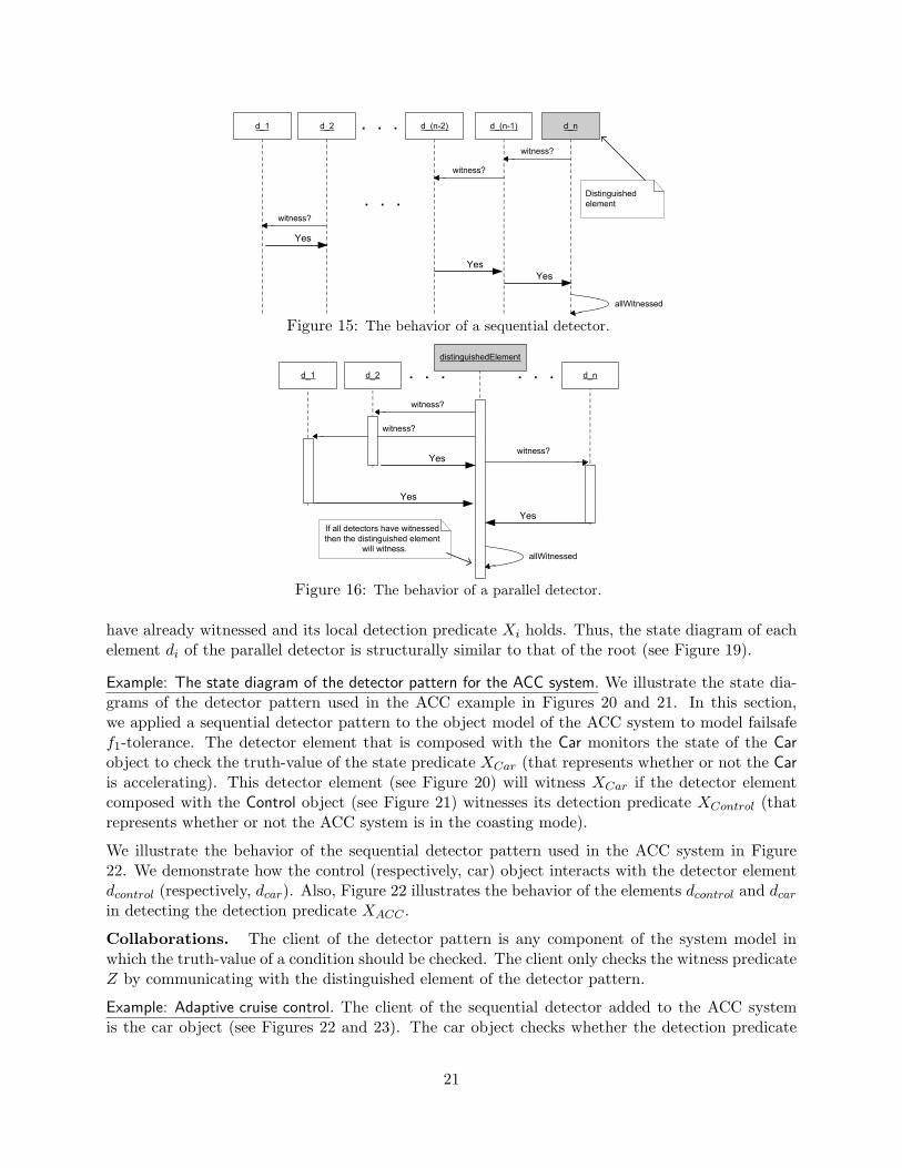
Behavior. The behavior of the detector pattern (see Figures 15 and 16) illustrates a solutionstrategy for the detection problem. We represent the behavior of a sequential detector in Figure15. To detect a global condition X ≡ X1 ∧ · · · ∧ Xn, the detector elements d1, · · · , dn detect theirlocal detection predicates sequentially until the global detection predicate X is detected by the lastelement dn (see Figure 15). More specifically, each element di is responsible for detecting its localdetection predicate Xi after all its predecessors d1, · · · , di−1 have witnessed their local detectionpredicates (2 ≤ i ≤ n). As a result, when dn witnesses, it follows that the detection predicate Xholds.
The elements of the parallel detector, d1, · · · , dn detect their local detection predicates concur-rently (see Figure 16). The global detection predicate is detected when all detector elements havewitnessed their local detection predicates simultaneously (see Figure 16). More specifically, thedistinguished element can witness when Z1 ∧ · · · ∧ Zn is true.
In the (sequential and parallel) detector pattern, each element di (1 ≤ i ≤ n) is concurrentlycomposed with objecti in the object model. In other words, the state diagram of the resultingcomposition will be a concurrent state comprising the state diagram of the detector element di
and the state diagram of objecti. We respectively demonstrate the state diagrams of d1 and di
19

object_1 object_n
. . .d_1 d_n
1
*
1
*
d_2
object_(n-1)
d_(n-1)
1
*
1
*
witnesses witnesses
detectsX_1 detectsX_2 detectsX_(n-1) detectsX_n
The n-th detector is the distinguished element that detects X
Sequential Detector
object_21 object_2j
. . .d_21 d_2j
. . .
1
*
1
*
object_2i
d_2i
1
*detectsX_21 detectsX_2i detectsX_2j
X-2 detector
witnesses
. . .
. . .
. . .
Parallel Detector
witnesseswitnesses
Figure 13: Composition of sequential and parallel detectors.
controlThrottle
detector_1 d_car
detectsCoasting detectsAcceleration
witnesses
CarControl
d_control
11
Figure 14: Composition of the sequential detector pattern with the ACC system.
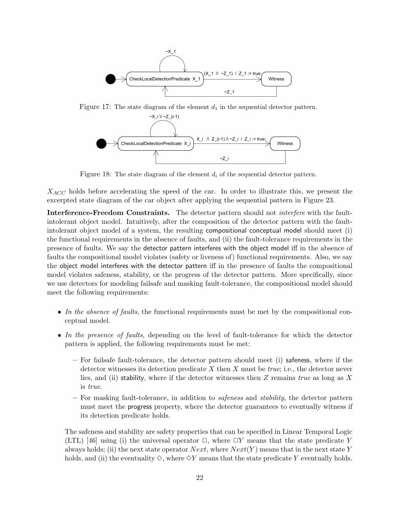
(1 < i ≤ n) in a sequential detector in Figures 17 and 18. The element d1 will witness if itslocal detection predicate X1 holds (see Figure 17), whereas di (1 < i ≤ n) will witness if not onlyits local detection predicate Xi holds, but also its predecessor has already witnessed (see Figure18), i.e., Z(i−1) is true. The detector element di, 1 ≤ i ≤ n, stays in its Witness state as longas Xi is true, i.e., stability (see Figures 17 and 18). More specifically, di must not be in theWitness state if its detection predicate Xi has been falsified (by fault or system actions). The faulttransitions may directly set the truth-value of Zi to false. In such cases, the detector di transitionsto the CheckLocalDetectionPredicate state and the safeness of the di is not violated. In cases whereobjecti updates its variables in such a way that Xi becomes false, the value of Zi should be set tofalse simultaneously. Otherwise, the safeness of di will be violated. Thus, objecti should atomicallyset the value of Zi to false whenever the actions of objecti falsify Xi. In the case of detector elementdn, the value of Zn should be atomically set to false if some Xi (1 ≤ i ≤ n) is being falsified.
We depict the state diagram of the distinguished element (i.e., the root) of the parallel detectorin Figure 19. In a parallel detector, the root witnesses its detection predicate if its local detectionpredicate Xroot holds and all its children have already witnessed their detection predicate. Recur-sively, this rule applies to other nodes of the parallel detector; i.e., di will witness if its children
20
d_1 d_(n-2) d_(n-1) d_n. . .
witness?
witness?
d_2
Yes
witness?
. . .
Yes
Yes
allWitnessed
Distinguished
element
Figure 15: The behavior of a sequential detector.
d_1
distinguishedElement
d_n. . .d_2
Yes
witness?
Yes
Yes
. . .
witness?
witness?
allWitnessed
If all detectors have witnessed
then the distinguished element
will witness.
Figure 16: The behavior of a parallel detector.
have already witnessed and its local detection predicate Xi holds. Thus, the state diagram of eachelement di of the parallel detector is structurally similar to that of the root (see Figure 19).
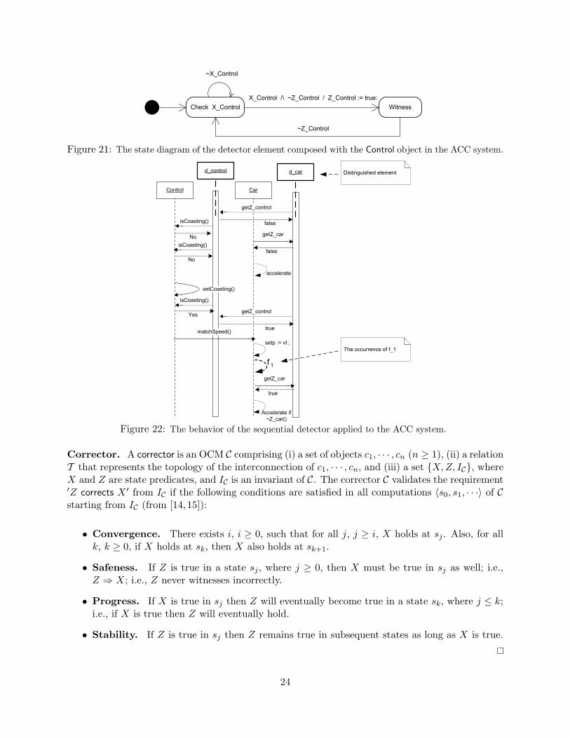
Example: The state diagram of the detector pattern for the ACC system. We illustrate the state dia-grams of the detector pattern used in the ACC example in Figures 20 and 21. In this section,we applied a sequential detector pattern to the object model of the ACC system to model failsafef1-tolerance. The detector element that is composed with the Car monitors the state of the Carobject to check the truth-value of the state predicate XCar (that represents whether or not the Caris accelerating). This detector element (see Figure 20) will witness XCar if the detector elementcomposed with the Control object (see Figure 21) witnesses its detection predicate XControl (thatrepresents whether or not the ACC system is in the coasting mode).
We illustrate the behavior of the sequential detector pattern used in the ACC system in Figure22. We demonstrate how the control (respectively, car) object interacts with the detector elementdcontrol (respectively, dcar). Also, Figure 22 illustrates the behavior of the elements dcontrol and dcar
in detecting the detection predicate XACC .
Collaborations. The client of the detector pattern is any component of the system model inwhich the truth-value of a condition should be checked. The client only checks the witness predicateZ by communicating with the distinguished element of the detector pattern.
Example: Adaptive cruise control. The client of the sequential detector added to the ACC systemis the car object (see Figures 22 and 23). The car object checks whether the detection predicate
21
CheckLocalDetectionPredicate X_1 Witness
(X_1 /\ ~Z_1) / Z_1 := true:
~X_1
~Z_1
Figure 17: The state diagram of the element d1 in the sequential detector pattern.
CheckLocalDetectionPredicate X_i WitnessX_i /\ Z_(i-1) /\ ~Z_i / Z_i := true:
~X_i \/ ~Z_(i-1)
~Z_i
Figure 18: The state diagram of the element di of the sequential detector pattern.
XACC holds before accelerating the speed of the car. In order to illustrate this, we present theexcerpted state diagram of the car object after applying the sequential pattern in Figure 23.
Interference-Freedom Constraints. The detector pattern should not interfere with the fault-intolerant object model. Intuitively, after the composition of the detector pattern with the fault-intolerant object model of a system, the resulting compositional conceptual model should meet (i)the functional requirements in the absence of faults, and (ii) the fault-tolerance requirements in thepresence of faults. We say the detector pattern interferes with the object model iff in the absence offaults the compositional model violates (safety or liveness of) functional requirements. Also, we saythe object model interferes with the detector pattern iff in the presence of faults the compositionalmodel violates safeness, stability, or the progress of the detector pattern. More specifically, sincewe use detectors for modeling failsafe and masking fault-tolerance, the compositional model shouldmeet the following requirements:
• In the absence of faults, the functional requirements must be met by the compositional con-ceptual model.
• In the presence of faults, depending on the level of fault-tolerance for which the detectorpattern is applied, the following requirements must be met:
– For failsafe fault-tolerance, the detector pattern should meet (i) safeness, where if thedetector witnesses its detection predicate X then X must be true; i.e., the detector neverlies, and (ii) stability, where if the detector witnesses then Z remains true as long as Xis true.
– For masking fault-tolerance, in addition to safeness and stability, the detector patternmust meet the progress property, where the detector guarantees to eventually witness ifits detection predicate holds.
The safeness and stability are safety properties that can be specified in Linear Temporal Logic(LTL) [46] using (i) the universal operator 2, where 2Y means that the state predicate Yalways holds; (ii) the next state operator Next, where Next(Y ) means that in the next state Yholds, and (ii) the eventuality 3, where 3Y means that the state predicate Y eventually holds.
22

CheckLocalDetectionPredicate X_root Witness(X_root /\ Z_1 /\ Z_2 /\ . . . /\ Z_n) / Z_i := true:
~X_root \/ ~Z_1 \/ ~Z_2 \/ . . . \/ ~Z_n
~Z_root
Figure 19: The state diagram of the root of the parallel detector pattern.
Check X_Car Witness
X_Car /\ Z_Control /\ ~Z_Car / Z_Car := true:
~X_Car \/ ~Z_Control
~Z_Car
Legend:
X_Car : Car is accelerating
X_Control : Control is in coasting mode
Z_Control : X_Control holds
Figure 20: The state diagram of the detector element composed with the Car object in the ACC system.
We respectively specify safeness and stability as 2(Z ⇒ X) and 2(Z ⇒ (Next(Z ∨ ¬X))).Also, we specify progress as the following LTL expression: 2(X ⇒ 3Z).
Example: Adaptive cruise control. The verification of the interference-freedom constraints can bedone by the substitution of the predicates Xcar, Zcar, Xcontrol, and Zcontrol in the above formulas.In Section 7, we illustrate how to generate formal specification of the detector pattern in Promela,where the SPIN model checker can be used for the verification of the interference-freedom con-straints. To ensure the interference-freedom of the sequential detector and the ACC system, wealso need to verify that the safety and liveness requirements of the ACC system (specified in Section3) hold in the absence of faults.
6 Corrector Pattern
In this section, we introduce the corrector analysis pattern that is used in modeling nonmaskingand masking fault-tolerance. The corrector pattern separates the concern of correcting a conditionfrom the rest of the analysis model. We first present a formal definition of the corrector pattern.Then we present the template of the corrector pattern and explain how to apply the pattern toUML object models.
6.1 Formal Specification of the Corrector Pattern
In this section, we extend the formal definition of correctors from [14, 15] in the context of OCM.We use correctors for modeling recovery in the presence of faults. Such recovery is necessary inspecifying nonmasking and masking fault-tolerant programs.
23
Check X_Control Witness
X_Control /\ ~Z_Control / Z_Control := true:
~X_Control
~Z_Control
Figure 21: The state diagram of the detector element composed with the Control object in the ACC system.
Control Car
matchSpeed()
setCoasting()
setp := vt ;
f 1
d_control d_car
isCoasting()
No
isCoasting()
No
isCoasting()
Yes
getZ_control
false
getZ_car
false
accelerate
getZ_control
true
getZ_car
true
Accelerate if
~Z_car()
Distinguished element
The occurrence of f_1
Figure 22: The behavior of the sequential detector applied to the ACC system.
Corrector. A corrector is an OCM C comprising (i) a set of objects c1, · · · , cn (n ≥ 1), (ii) a relationT that represents the topology of the interconnection of c1, · · · , cn, and (iii) a set {X,Z, IC}, whereX and Z are state predicates, and IC is an invariant of C. The corrector C validates the requirement′Z corrects X ′ from IC if the following conditions are satisfied in all computations 〈s0, s1, · · ·〉 of Cstarting from IC (from [14,15]):
• Convergence. There exists i, i ≥ 0, such that for all j, j ≥ i, X holds at sj . Also, for allk, k ≥ 0, if X holds at sk, then X also holds at sk+1.
• Safeness. If Z is true in a state sj , where j ≥ 0, then X must be true in sj as well; i.e.,Z ⇒ X; i.e., Z never witnesses incorrectly.
• Progress. If X is true in sj then Z will eventually become true in a state sk, where j ≤ k;i.e., if X is true then Z will eventually hold.
• Stability. If Z is true in sj then Z remains true in subsequent states as long as X is true.
24

CalculatingRealV
if (~Z_car()) then Accelerating Decelerating
[~disengaged]
[Realv < setp]
[radarAck()]
[Realv > setp]
[radarAck()]
f1
Check with d_car
before acceleration
Figure 23: The excerpted state diagram of the car after applying the sequential detector pattern.
Intuitively, the convergence property guarantees that if X is false, then it will eventually becometrue and will stay true thereafter. In other words, a corrector C guarantees to correct the truth-value of the predicate X whenever X becomes false. Also, the state predicate Z witnesses thatsuch correction has happened. Therefore, if Z is true, then X must have been corrected. If X hasbecome true, then Z will eventually become true. Note that, if ′Z corrects X ′, then ′Z detects X ′
as well because C meets safeness, progress, and stability.
6.2 Corrector Pattern Template
In this section, we present the template of the corrector pattern. Also, in the context of the ACCexample, we illustrate how correctors can be used for providing nonmasking f2-tolerance.
Correction Problem. In order to provide a desired behavior in the presence of faults, a fault-tolerant system should guarantee some post conditions after it finds itself in an error state. Thesatisfaction of such post conditions prevents the occurrence of behavioral failures that may originateat error states. Extant fault-tolerance techniques such as error correction codes, recovery blocks [1],replicated state machines [4], and roll-back (respectively, roll-forward) recovery [6] are differentmechanisms for correcting the state of computing systems. The corrector pattern generalizes therecurring problem of correcting the state of a computing system after the detection of error states.
Example: Adaptive cruise control. In the ACC system, we need to correct the invariant wheneverit is falsified due to the occurrence of f2. Specifically, the occurrence of fault-type f2 (introducedin Section 3.1) may perturb the ACC system to a state s where the condition Brakes(s) ⇒disengaged(s) does not hold; i.e., the driver has applied the brakes, but the car has not disengagedfrom the cruise mode. The falsification of Brakes(s) ⇒ disengaged(s) results in the falsificationof the invariant IACC .
Intent. The corrector pattern (i) formulates instances of the correction problem, and (ii) providesan abstract decomposition strategy for the correction problem.
Applicability. The corrector pattern can be used in cases where one needs to ensure that thestate of a computing system will eventually satisfy a particular condition. Thus, in the presenceof faults, if the state of a computing system is perturbed outside its invariant then the correctorpattern can be used to ensure the recovery of the system to its invariant.
Correction Predicate. A correction predicate X represents the condition whose truth-valueshould be set to true once it becomes false. In a distributed system, it may not be possible tocorrect the truth-value of a state predicate in an atomic step. Thus, the correction of a globalstate predicate should be decomposed to a sequence of local corrective actions. In other words, the
25
problem of correcting a global state predicate will be decomposed to the correction of a set of localpredicates.
Example: Adaptive cruise control. The occurrence of f2 may take the ACC system to a state s,where the car is not disengaged even though brakes are applied. We represent this situation bythe correction predicate Y ⇒ W , where Y ≡ Brakes(s) and W ≡ disengaged(s). To providenonmasking f2-tolerance, we must ensure that the constraint Y ⇒ W will eventually hold after f2
stops occurring.
Witness Predicate. A witness predicate Z is a local state predicate whose truth-value of trueimplies that the correction predicate X holds.
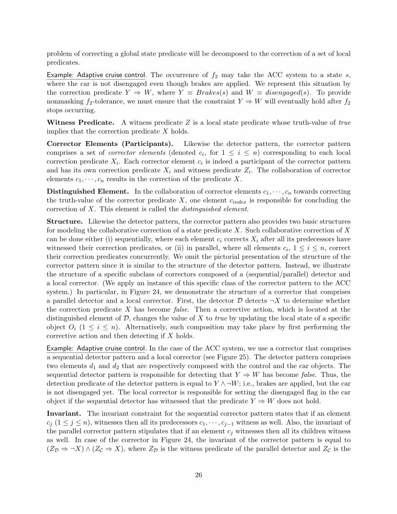
Corrector Elements (Participants). Likewise the detector pattern, the corrector patterncomprises a set of corrector elements (denoted ci, for 1 ≤ i ≤ n) corresponding to each localcorrection predicate Xi. Each corrector element ci is indeed a participant of the corrector patternand has its own correction predicate Xi and witness predicate Zi. The collaboration of correctorelements c1, · · · , cn results in the correction of the predicate X.
Distinguished Element. In the collaboration of corrector elements c1, · · · , cn towards correctingthe truth-value of the corrector predicate X, one element cindex is responsible for concluding thecorrection of X. This element is called the distinguished element.
Structure. Likewise the detector pattern, the corrector pattern also provides two basic structuresfor modeling the collaborative correction of a state predicate X. Such collaborative correction of Xcan be done either (i) sequentially, where each element ci corrects Xi after all its predecessors havewitnessed their correction predicates, or (ii) in parallel, where all elements ci, 1 ≤ i ≤ n, correcttheir correction predicates concurrently. We omit the pictorial presentation of the structure of thecorrector pattern since it is similar to the structure of the detector pattern. Instead, we illustratethe structure of a specific subclass of correctors composed of a (sequential/parallel) detector anda local corrector. (We apply an instance of this specific class of the corrector pattern to the ACCsystem.) In particular, in Figure 24, we demonstrate the structure of a corrector that comprisesa parallel detector and a local corrector. First, the detector D detects ¬X to determine whetherthe correction predicate X has become false. Then a corrective action, which is located at thedistinguished element of D, changes the value of X to true by updating the local state of a specificobject Oi (1 ≤ i ≤ n). Alternatively, such composition may take place by first performing thecorrective action and then detecting if X holds.
Example: Adaptive cruise control. In the case of the ACC system, we use a corrector that comprisesa sequential detector pattern and a local corrector (see Figure 25). The detector pattern comprisestwo elements d1 and d2 that are respectively composed with the control and the car objects. Thesequential detector pattern is responsible for detecting that Y ⇒ W has become false. Thus, thedetection predicate of the detector pattern is equal to Y ∧¬W ; i.e., brakes are applied, but the caris not disengaged yet. The local corrector is responsible for setting the disengaged flag in the carobject if the sequential detector has witnessed that the predicate Y ⇒ W does not hold.
Invariant. The invariant constraint for the sequential corrector pattern states that if an elementcj (1 ≤ j ≤ n), witnesses then all its predecessors c1, · · · , cj−1 witness as well. Also, the invariant ofthe parallel corrector pattern stipulates that if an element cj witnesses then all its children witnessas well. In case of the corrector in Figure 24, the invariant of the corrector pattern is equal to(ZD ⇒ ¬X) ∧ (ZC ⇒ X), where ZD is the witness predicate of the parallel detector and ZC is the
26

object_1 object_n
. . .d_1 d_n
. . .1
*
1
*
object_i
d_i
1
*
witnesses witnesses
detects ~X
distinguished element
witnesses
. . .
. . .
Partial System Model
Parallel Detector
LocalCorrectorCorrector
corrects
Figure 24: The structure of a detector composed with a local corrector.
controlThrottle
detector_1 d_2
detectBrakes detect~Disengaged
witnesses
CarControl
d_1
1 1
localCorrector
witnesses
correct(Y => W)
Figure 25: The structure of the corrector composed with the object model of the ACC system.
witness predicate of the local corrector.
Example: Adaptive cruise control. The invariant of the corrector used to add nonmasking f2-toleranceto the ACC system is equal to (Zd2 ⇒ (Y ∧ ¬W )) ∧ (ZC ⇒ (Y ⇒ W )), where ZC is the witnesspredicate of the local corrector.
Behavior. In Figure 26, we illustrate the behavior of the corrector pattern of Figure 24. First,the parallel detector detects that the state predicate X does not hold. Then the local correctorupdates the state of some object objecti, which in turn results in the correction of X.
Example: Adaptive cruise control. We illustrate the behavior of the corrector pattern composed withthe ACC object model in Figure 27. This Figure depicts (i) the collaborations between the sequen-tial detector pattern and the local corrector, and (ii) the collaborations between the elements ofthe detector pattern and the car and control objects.
Collaborations. The client of the corrector pattern is any component of the system object modelin which the correction predicate X is set to true after it becomes false. The client only checks thewitness predicate Z to verify whether or not X holds.
Interference-Freedom Constraints. To ensure that there is no conflict between fault-tolerance
27
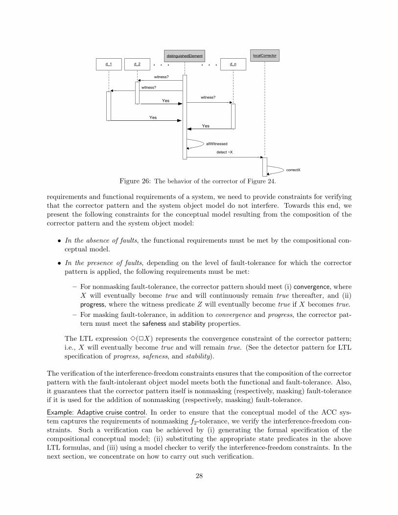
d_1
distinguishedElement
d_n. . .d_2
Yes
witness?
Yes
Yes
. . .
witness?
witness?
allWitnessed
localCorrector
detect ~X
correctX
Figure 26: The behavior of the corrector of Figure 24.
requirements and functional requirements of a system, we need to provide constraints for verifyingthat the corrector pattern and the system object model do not interfere. Towards this end, wepresent the following constraints for the conceptual model resulting from the composition of thecorrector pattern and the system object model:
• In the absence of faults, the functional requirements must be met by the compositional con-ceptual model.
• In the presence of faults, depending on the level of fault-tolerance for which the correctorpattern is applied, the following requirements must be met:
– For nonmasking fault-tolerance, the corrector pattern should meet (i) convergence, whereX will eventually become true and will continuously remain true thereafter, and (ii)progress, where the witness predicate Z will eventually become true if X becomes true.
– For masking fault-tolerance, in addition to convergence and progress, the corrector pat-tern must meet the safeness and stability properties.
The LTL expression 3(2X) represents the convergence constraint of the corrector pattern;i.e., X will eventually become true and will remain true. (See the detector pattern for LTLspecification of progress, safeness, and stability).
The verification of the interference-freedom constraints ensures that the composition of the correctorpattern with the fault-intolerant object model meets both the functional and fault-tolerance. Also,it guarantees that the corrector pattern itself is nonmasking (respectively, masking) fault-toleranceif it is used for the addition of nonmasking (respectively, masking) fault-tolerance.
Example: Adaptive cruise control. In order to ensure that the conceptual model of the ACC sys-tem captures the requirements of nonmasking f2-tolerance, we verify the interference-freedom con-straints. Such a verification can be achieved by (i) generating the formal specification of thecompositional conceptual model; (ii) substituting the appropriate state predicates in the aboveLTL formulas, and (iii) using a model checker to verify the interference-freedom constraints. In thenext section, we concentrate on how to carry out such verification.
28

Control Car
faults may corrupt the
state of the ACC system
outside its invariant
f2
disengaged := false ;
d_1 d_2 localCorrector
detect~W
setBrakes()
isBrakes()
YesisDisengaged()
Yes
witnesses()
Yes
~W
Yes
setDisengaged()
witness()
Figure 27: The behavior of the corrector pattern composed with the ACC system.
7 Formal Analysis of Fault-Tolerant Systems
In this section, we demonstrate how to generate formal specification of the detector and correctorpatterns in Promela modeling language [16]. Also, we present a method for formal specificationof faults in Promela. The formalization presented in this section enables us to use the SPINmodel checker [17] in analyzing the inconsistencies of fault-tolerance requirements with functionalrequirements (if any). More importantly, the detector and corrector patterns provide a level ofmodularity that helps us in (i) pinpointing the source of inconsistencies, and (ii) resolving theinconsistencies between functional and fault-tolerance requirements.
7.1 Formalizing Detector and Corrector Patterns
In this section, we present a formal template for the detector pattern in Promela. We omit thepresentation of the template of the corrector pattern as it is similar to the detector pattern. We useHydra formalization framework [9,10] to generate the template. Also, we use Hydra to generate thePromela specification of the functional object model that is concurrently run with the detector andcorrector patterns. Before presenting the Promela code of the detector pattern, we briefly reviewPromela and Hydra.
The Promela modeling language. Promela is a language for modeling concurrent and dis-tributed programs in the model checker SPIN [17]. Using SPIN, developers can verify the modelof a computing system (specified in Promela) with respect to a set of desired properties specifiedin Linear Temporal Logic (LTL) [46]. Also, SPIN enables simulation of the system model for val-idation purposes. The syntax of Promela is based on the C programming language. A Promelamodel comprises (1) a set of variables, (2) a set of (concurrent) processes modeled by a predefinedtype, called proctype, and (3) a set of asynchronous and synchronous channels for inter-process
29

communications. Semantically, Promela is a descendent of Dijkstra’s guarded commands [47] andCSP [48] except that there exist no mechanisms for inter-process communications in guarded com-mands language. Also, Promela is more general than CSP in that Promela allows the use of bufferedchannels, whereas in CSP processes communicate only via rendezvous channels; i.e., synchronizedunbuffered channels.
The Hydra formalization framework. Hydra [9, 10] is a generic framework for generatingformal specification from textual representation of UML (structural/behavioral) diagrams. Specif-ically, Hydra uses a set of mapping rules for translating entities in UML meta-model to entities inthe meta-model of a target specification language (e.g., Promela). For example, Hydra translatestwo concurrent states specified in UML state diagrams to two concurrent proctypes specified inPromela. Using Hydra, we translate UML models to Promela specification language, which in turnenables us to verify (respectively, validate) UML models against properties of interest.
Generating Promela code for the detector pattern. Hydra generates the following proctypefor an element di in the sequential detector pattern, which is concurrently run with the proctype ofthe composed object objecti (see Figures 11 and 12). The structure of the Promela code generatedfor the parallel detector pattern is also similar to the following template.
1 proctype d_i() {2 do3 :: atomic{ X_i && Z_(i-1) && !Z_i -> Z_i = true; }4 od;5}6
7 proctype object_i() {8 /* The actions of object_i */
9 }
The state predicates Xi, Zi, and Z(i − 1) in the above Promela code are defined in terms of thevariables in the locality of objecti, which is composed with di. Thus, although the above templatecould be used for different object models, the state predicates should be instantiated based on thestate variables of objecti in the object model. Also, the communication between different detectorelements takes place using their shared variables. For example, in the above code, the element di
reads the witness predicate of the element di−1, i.e., Zi−1.
Example: The Promela code for the detector pattern of the ACC system. The formalization of the de-tector pattern for the ACC system results in the following Promela code, which is an instantiationof the template introduced above.
1 proctype d_Car() {2 do3 :: atomic{ (CarState == Accelerating) && Z_Control && !Z_Car -> Z_Car = true; }4 od;5}6
7 proctype Car() {8
9 /* The actions of the Car object. */
10
11 }
The Xcar has been substituted with the predicate (CarState == Accelerating), where CarState is
30

a variable that represents the current state of the car object. Since the predecessor of the detectorelement dcar (see Figure 14) is dcontrol, the predicate Zi−1 has been substituted with Zcontrol.
7.2 Formalizing the Fault Model
In this section, we illustrate how to model faults in Promela. Also, we discuss issues related toexecuting the fault model in SPIN. As mentioned in Section 4, we model a fault-type as a set oftransitions in UML object models. In order to model faults in Promela, Hydra integrates all faulttransitions in a Fault process that could be executed concurrently with all other processes in theexecutable model. For example, in the case of the ACC system, Hydra generates the followingPromela code to represent all types of faults that perturb the cruise control system.
1 proctype Fault() {2 if
3 :: atomic{ Car. CarState == CalculatingRealV -> Car.CarState = Accelerating; }4 :: atomic{ Car.disengaged = true -> Car.disengaged = false; }5 :: atomic{ Control.closing = true -> Control.closing = false; }6 :: atomic{ Control.matching = true -> Control.matching = false; }7 :: atomic{ Control.coasting =true -> Control.coasting = false; }8 fi
9}
Each action of the above Promela code represents a set of transitions in the entire state space ofthe object model. (For simplicity, we have attached the name of each variable to the name of theobject that owns that variable.) Also, note that, in the Promela model, all actions are executed inan atomic step.
The execution of the Fault proctype must conform with the formal model of faults defined in OCM(see Section 2.5). More specifically, the Fault proctype should represent a process with terminatingcomputations; i.e., the Fault process will terminate in a finite amount of time. This is a realizationof the assumption made in Section 2.5 that faults will eventually stop occurring so that recoverycan be provided by the corrector pattern.
The semantics of the execution of the Fault proctype in SPIN depends on the model of fairnessselected while simulating (respectively, verifying) the fault-tolerant object model. Since, by default,SPIN does not guarantee fair execution of all processes [49], there exists a possibility that the Faultproctype will never get an execution chance during the simulation (respectively, verification) ofthe fault-tolerant model. Thus, during simulation (respectively, verification) of fault-tolerancerequirements, the fairness option in SPIN should be set so that the Fault process is executed alongother processes. Since the Fault process will eventually terminate, the fault-tolerant model shouldeventually meet its liveness requirements (after recovery to the invariant).
7.3 Analyzing the Inconsistencies of Fault-Tolerance and Functional Require-ments
In this section, we present a strategy for analyzing fault-tolerance and functional requirements usingthe SPIN model checker [17]. Specifically, we specify the steps that must be taken in creating aconsistent conceptual model for fault-tolerant systems (after the generation of the Promela code).
31

In this section, our focus is on the conceptual model of fault-tolerant systems that is the compositionof the functional object model and the detector/corrector patterns.
In order to analyze the consistency of the fault-tolerance requirements with the functional require-ments, we first exclude the Fault proctype from the Promela code of the object model. Then weverify (respectively, validate) the safety and liveness requirements. This step ensures that in theabsence of faults the failsafe fault-tolerant model meets its functional requirements. To analyze thefault-tolerant object model in the presence of faults, we include the Fault proctype in the Promelacode of the object model, and we select one of the following steps:
• To verify (respectively, validate) the failsafe fault-tolerance requirements, we ensure that thesafety requirements hold.
• To verify (respectively, validate) the nonmasking fault-tolerance requirements, we ensure thatthe object model will eventually recover to its invariant.
• To verify (respectively, validate) the masking fault-tolerance requirements, we ensure that (i)the safety requirements hold, and (ii) the object model will eventually recover to its invariant.
• In addition to the above steps, we have to verify that (i) each instance of the detector/correctorpattern that is used for providing failsafe (respectively, nonmasking or masking) fault-toleranceis itself failsafe (respectively, nonmasking or masking) fault-tolerant. This can be achievedby verifying the interference-freedom constraints specified (in LTL) in Sections 5 and 6.
The counterexamples generated during the above verification steps represent the inconsistencies offault-tolerance and functional requirements. Specifically, if SPIN generates counterexample duringthe verification of interference-freedom constraints then those counterexamples represent scenarioswhere fault-tolerance requirements are inconsistent with the functional requirements. Using suchcounterexamples, the analysts can revise the conceptual model of a fault-tolerant system at theearly stages of development. For example, in the conceptual model of the ACC fault-tolerantsystem, if after dcar witnesses that its detection predicate Xcar ≡ (car is accelerating) holds (i.e.,dcar sets the value of Zcar to true) the state of the car object is change to another state withoutfalsifying Zcar then the safeness of dcar will be violated. To remedy this inconsistency, we revisethe object model in that any transition originating at the Accelerating state should be accompaniedwith the simultaneous falsification of Zcar.
8 Analysis Method
In this section, we give an overview of our analysis method, where we (i) emphasize the challengesthat exist in the development of fault-tolerant systems, and (ii) motivate the analysis method thatwe introduce in this paper. Also, we define what we mean by (detector/corrector) patterns in theanalysis phase (since one may think of the term pattern as a design concept).
At the early stages of system development, it is difficult (if not impossible) to anticipate all typesof faults that may perturb a system. Thus, as developers encounter new types of faults, they haveto add desired level of fault-tolerance to an existing system. Clearly, such an addition of fault-tolerance should (i) preserve the functionalities of the existing system in the absence of faults, and
32

(ii) provide the required level of fault-tolerance in the presence of faults. Moreover, adding fault-tolerance against a newly discovered fault-type should preserve fault-tolerance properties that havealready been added against other types of faults. Due to such complex mixture of functional andfault-tolerance requirements, we need systematic (and preferably automatic) methods for modelingand analyzing fault-tolerance requirements before entering design and implementation phases.
In order to provide a systematic approach for the development of fault-tolerant systems, we presentan incremental modeling and analysis method that includes two major steps: elicitation and speci-fication of fault-tolerance requirements, and building conceptual models for automated analysis. Tospecify fault-tolerance requirements, we start with identifying problems (i.e., constraints) that mustbe solved towards providing fault-tolerance. Based on necessity and sufficiency of detectors andcorrectors for designing fault-tolerance requirements [14,15], we focus on identifying detection andcorrection constraints. The use of detection/correction constraints (i) separates fault-tolerance andfunctional concerns; (ii) separates fault-tolerance concerns added for different types of faults, and(iii) provides traceability throughout the entire software development lifecycle.
To build the conceptual model of fault-tolerant systems, we present fault-tolerance analysis patternsfor problem decomposition. In this paper, an analysis pattern is an abstract strategy for decom-posing a problem into subproblems. Likewise Jackson [50], our focus is on identifying problemsthat should be solved towards providing fault-tolerance. Moreover, we move one step further inpresenting techniques for decomposing a problem to smaller problems using our analysis patterns.Our notion of analysis patterns differs from Fowler’s analysis patterns [51] in that (1) Fowler’sanalysis patterns represent recurring ideas for business modeling, whereas our fault-tolerance anal-ysis patterns are recurring problems that must be solved for supporting fault-tolerance, and (2)Fowler’s analysis patterns are the outcome of the modeler’s experience in a particular domain, andas a result, they may be an incomplete set of patterns for the subject domain, whereas our fault-tolerance analysis patterns comprise a canonical set of patterns that are necessary and sufficientfor specifying fault-tolerance.
We present an overview of our analysis method in Figure 28. When developers encounter a newfault-type that perturbs an existing system, the first step is to model faults and fault-tolerancerequirements in the use case model of the existing fault-intolerant system (see Section 3). Thespecification of the fault-tolerance requirements comprises of specifying detection and correctionconstraints. Then, at the object analysis level, developers have to use detector and correctorpatterns (see Sections 5 and 6) for the refinement of fault-tolerance constraints. The resultingartifact would be a conceptual model that contains the conceptual model of the fault-intolerantsystem composed with detector and corrector patterns. Finally, we generate formal specificationfrom the fault-tolerant conceptual model for automated analysis. Specifically, developers have toverify the interference-freedom of fault-tolerance analysis patterns and the fault-intolerant model;i.e., the detector and corrector patterns and the fault-intolerant model meet their requirements inthe presence of each other. If the fault-tolerance analysis patterns and the fault-intolerant modelinterfere then developers should modify the fault-tolerant conceptual model towards resolving theinconsistencies. Nonetheless, ensuring interference-freedom is out of the scope of this paper sinceour goal is to create the necessary framework for automated analysis of such inconsistencies betweenfunctional and fault-tolerance requirements.
33

Model faults
Valid UML model of the fault-intolerant system
(i.e., use case/class/state/sequence diagrams)
UML model
with faults
Specify detection/correction constraints
(e.g., error conditions)
Model check the
conceptual model
(e.g., using SPIN)
Conceptual UML model
(i.e., composition of the functional
UML model and the detector/
corrector patterns)
Instantiate the detector/
corrector analysis patterns
in the UML model with faults
Formal specification of
the conceptual model
Generate formal
specifications
(e.g., Promela code)
A UML model of
the fault-tolerant
systemModel checking
successful?
Yes
Modeling artifact Process
Legend
Data flowDecision
No
Revise the conceptual model
Figure 28: An overview of the analysis method.
9 Diesel Filter System
In this section, we illustrate how to use an instance of the detector pattern to model failsafe fault-tolerance in the object model of a Diesel Filter System (DFS) introduced in [52]. In the contextof this case study, we are interested in modeling and analyzing failsafe fault-tolerance using thedetector pattern. Thus, we focus on the aspects of the DFS system related to our analysis. The DFSis an embedded computing system used to reduce soot from diesel truck exhaust (see Figure 29).The DFS system comprises a canister containing a filter placed into the exhaust pipe, where theexhaust gas flows through the filter. A filter has several tubes consisting of ceramic fibers wrappedaround a metallic cylindrical grid. Due to the exhaust gas flow, the filter becomes clog up after awhile and it needs to be cleaned. The cleaning is achieved by heating up the grid (using heatersmounted around the metallic grid) and burning off the trapped soot. The DFS controller initiatesthe cleaning cycle whenever the differential pressure across the canister is beyond a pre-determinedthreshold. A pressure sensor provides the current differential pressure to the DFS controller. We
34

illustrate an excerpted class diagram of the DFS system in Figure 30.
exhaust
+ soot
Filter Canister
exhaust
- soot����������������������������������������������������������������������������������������������������������������������������������������������������������������������������������������������������������������������������������������������������������������������������������������������������������������������������������������������������������������������������������������������������������������������������������������������������������������������������������������������������������������������������������������������������������������������������������������������������������������������������������������������������������������������������������������������������������������������������������������������������������������������������������������������������������������������������������������������������������������������������������������������������������������������������������������������������������������������������������������������������������������������������������������������������������������������������������������������������������������������������������������������
Filter Element
Heating Element
Heating Element
PressureSensor
FilterControlModule
EngineControlModule
+-
Figure 29: Physical structure of a diesel filter system.
• The PressureSensor class models the pressure sensor, which only provides the differentialpressure across the filter canister to the FilterController class (i.e., the pressure sensor is apassive element and does not processing).
• The FilterController class models the controlling functionalities of the DFS. The FilterControllerclass has three operating modes. The DFS is in the idle mode if the current pressure measuredby the pressure sensor is between 0 and 8000 Pascals (Pa). In the idle mode, the FilterControllerremains inactive. If the pressure is above 8000 Pa and less than or equal to 10000 Pa, thenthe FilterController enters the cleaning mode, where it starts a cleaning cycle by electrifyingthe heaters. The FilterController enters the safety mode if the sensed pressure is above 10000Pa, where the FilterController must not initiate the heating process.
• The EngineController class models the engine control module that measures the current enginespeed. The EngineController.totalRPM variable keeps the total number of engine revolutionssince last cleaning cycle, and the EngineController.currRPM variable represents the currentspeed of the engine.
• The HeatRegulator class models a heater installed in the filter canister, and the HeatRegu-lator.cleanupValue represent a value set by the FilterController that determines how fast theheating should be done.
• The HeaterCurrentSensor class models the passive sensor used to measure the value of theelectrical current in the heater regulator.
Safety requirements of the DFS system. The cleaning cycle should not be started if lessthan 10000 engine revolutions have occurred since the last cleaning cycle or if the current enginerevolutions per minute (RPM) is less than 700. (The engine control module (see Figure 29) measuresthe current RPM.) Moreover, the heating elements must not be defected (represented by a negativevalue of HeaterCurrentSensor.electricalCurrent) if the DFS controller is to activate the heaters.
We present the state diagram of the FilterController in Figure 31. The controller starts by checkingthe pressure of the filter canister. Depending on the value of the pressure received form the pressuresensor, the controller transitions to the Idle, Ready, or Safety states. In the Idle state, the controller
35
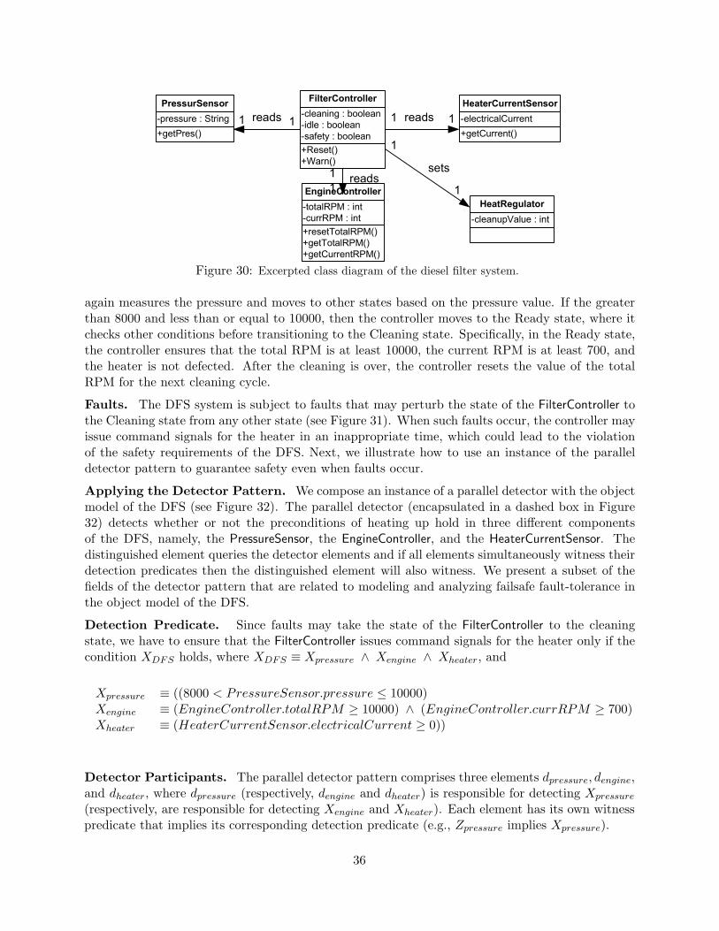
+Reset()
+Warn()
-cleaning : boolean
-idle : boolean
-safety : boolean
FilterController
+getPres()
-pressure : String
PressurSensor
-cleanupValue : int
HeatRegulator
+resetTotalRPM()
+getTotalRPM()
+getCurrentRPM()
-totalRPM : int
-currRPM : int
EngineController
+getCurrent()
-electricalCurrent
HeaterCurrentSensor
reads
reads reads
sets
1
1
1
1
11
1
1
Figure 30: Excerpted class diagram of the diesel filter system.
again measures the pressure and moves to other states based on the pressure value. If the greaterthan 8000 and less than or equal to 10000, then the controller moves to the Ready state, where itchecks other conditions before transitioning to the Cleaning state. Specifically, in the Ready state,the controller ensures that the total RPM is at least 10000, the current RPM is at least 700, andthe heater is not defected. After the cleaning is over, the controller resets the value of the totalRPM for the next cleaning cycle.
Faults. The DFS system is subject to faults that may perturb the state of the FilterController tothe Cleaning state from any other state (see Figure 31). When such faults occur, the controller mayissue command signals for the heater in an inappropriate time, which could lead to the violationof the safety requirements of the DFS. Next, we illustrate how to use an instance of the paralleldetector pattern to guarantee safety even when faults occur.
Applying the Detector Pattern. We compose an instance of a parallel detector with the objectmodel of the DFS (see Figure 32). The parallel detector (encapsulated in a dashed box in Figure32) detects whether or not the preconditions of heating up hold in three different componentsof the DFS, namely, the PressureSensor, the EngineController, and the HeaterCurrentSensor. Thedistinguished element queries the detector elements and if all elements simultaneously witness theirdetection predicates then the distinguished element will also witness. We present a subset of thefields of the detector pattern that are related to modeling and analyzing failsafe fault-tolerance inthe object model of the DFS.
Detection Predicate. Since faults may take the state of the FilterController to the cleaningstate, we have to ensure that the FilterController issues command signals for the heater only if thecondition XDFS holds, where XDFS ≡ Xpressure ∧ Xengine ∧ Xheater, and
Xpressure ≡ ((8000 < PressureSensor.pressure ≤ 10000)Xengine ≡ (EngineController.totalRPM ≥ 10000) ∧ (EngineController.currRPM ≥ 700)Xheater ≡ (HeaterCurrentSensor.electricalCurrent ≥ 0))
Detector Participants. The parallel detector pattern comprises three elements dpressure, dengine,and dheater, where dpressure (respectively, dengine and dheater) is responsible for detecting Xpressure
(respectively, are responsible for detecting Xengine and Xheater). Each element has its own witnesspredicate that implies its corresponding detection predicate (e.g., Zpressure implies Xpressure).
36

CheckPressure
Idle
Ready
Safety
[8000 < PressureSensor.getPres() <= 10000]
[10000 < PressureSensor.getPres() ]
[8000 < PressureSensor.getPres() <= 10000]
Cleaning
[Q]
Q ≡ (8000 < PressureSensor.getPres() <= 10000) AND
(EngineController.getTotalRPM() >= 10000) AND
(EngineController.getCurrRPM() >= 700) AND
(HeaterCurrentSensor.getCurrent() >= 0)
[~Q]
/ EngineController.resetTotalRPM()
Legend
[10000 <
PressureSensor.getPres()]
[PressureSensor.getPres() <= 8000]
ShuttingDown
[0 <= PressureSensor.getPres() <= 8000]
/Reset()
/Warn()
Fault transition:
Figure 31: An abstract state diagram of the filter controller.
Distinguished element and the witness predicate. The distinguished element is an objectthat is the owner of the witness predicate ZDFS , where ZDFS implies that XDFS holds and ZDFS ≡(Zpressure ∧ Zengine ∧ Zheater).
Detection Requirements. Since we use the parallel detector to model failsafe fault-tolerance,only the safeness and the stability of the detector pattern should be met. Thus, the composition ofthe DFS object model and the parallel detector pattern should satisfy the following LTL properties:
• Safeness. The safeness of the parallel detector requires that 2(ZDFS ⇒ 3XDFS).
• Stability. The stability requires that 2(ZDFS ⇒ (Next(ZDFS ∨ ¬XDFS))) always holds.
Also, all participants of the parallel detector pattern must meet the safeness and the stabilityrequirements. For example, the participant dpressure should meet the following:
37

reads
reads reads
sets
queries
queries queries
queriesqueries
queries
queries
distinguishedElement:
d_pressure:
HeaterCurrentSensor:
d_engine: d_heater:
FilterController:
HeatRegulator:
PressureSensor:
EngineController:
Figure 32: The composition of a parallel detector and the object model of the diesel filter system.
• Safeness. The safeness of dpressure requires that 2(Zpressure ⇒ 3Xpressure).
• Stability. The stability requires that 2(Zpressure ⇒ (Next(Zpressure ∨ ¬Xpressure))) alwaysholds.
Collaborations. The FilterController object is the client of the parallel detector pattern since itchecks the truth-value of ZDFs before it issues any command signals to the heater. We illustratethis collaborative relation between the parallel detector pattern and the FilterController object inthe state diagram of Figure 33.
Interference-Freedom Constraints. In order to ensure that the object model of the DFS andthe instance of the parallel detector pattern do not interfere, we verify the following requirements(using model checking techniques):
• In the absence of faults, we verify that if the FilterController object is in the Cleaning state,then XDFS must hold. Also, we verify that the FilterController object never deadlocks.
• In the presence of faults, we verify the safeness and the stability of the parallel detector pat-tern. Moreover, we verify that the FilterController object never violates the safety requirementsof the DFS.
38
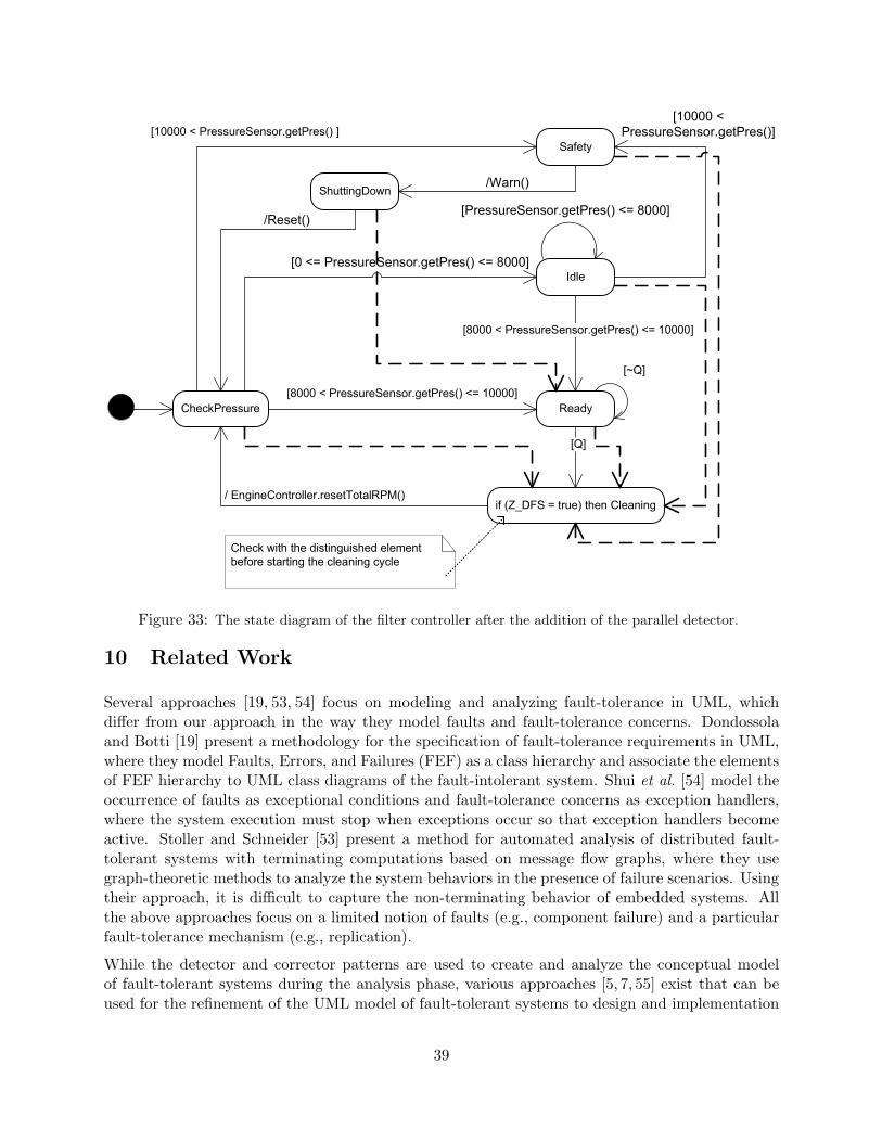
CheckPressure
Idle
Ready
Safety
[8000 < PressureSensor.getPres() <= 10000]
[10000 < PressureSensor.getPres() ]
[8000 < PressureSensor.getPres() <= 10000]
if (Z_DFS = true) then Cleaning
[Q]
[~Q]
/ EngineController.resetTotalRPM()
[10000 <
PressureSensor.getPres()]
[PressureSensor.getPres() <= 8000]
ShuttingDown
[0 <= PressureSensor.getPres() <= 8000]
/Reset()
/Warn()
Check with the distinguished element
before starting the cleaning cycle
Figure 33: The state diagram of the filter controller after the addition of the parallel detector.
10 Related Work
Several approaches [19, 53, 54] focus on modeling and analyzing fault-tolerance in UML, whichdiffer from our approach in the way they model faults and fault-tolerance concerns. Dondossolaand Botti [19] present a methodology for the specification of fault-tolerance requirements in UML,where they model Faults, Errors, and Failures (FEF) as a class hierarchy and associate the elementsof FEF hierarchy to UML class diagrams of the fault-intolerant system. Shui et al. [54] model theoccurrence of faults as exceptional conditions and fault-tolerance concerns as exception handlers,where the system execution must stop when exceptions occur so that exception handlers becomeactive. Stoller and Schneider [53] present a method for automated analysis of distributed fault-tolerant systems with terminating computations based on message flow graphs, where they usegraph-theoretic methods to analyze the system behaviors in the presence of failure scenarios. Usingtheir approach, it is difficult to capture the non-terminating behavior of embedded systems. Allthe above approaches focus on a limited notion of faults (e.g., component failure) and a particularfault-tolerance mechanism (e.g., replication).
While the detector and corrector patterns are used to create and analyze the conceptual modelof fault-tolerant systems during the analysis phase, various approaches [5, 7, 55] exist that can beused for the refinement of the UML model of fault-tolerant systems to design and implementation
39

phases. For example, Beder et al. [5] use design patterns to implement Coordinated Atomic Actions(CAA) in the design and implementation of error-handling mechanisms in distributed O-O systems.Also, Tichy et al. [55] present a pattern-based approach for the design of service-based systems inUML, based on the redundancy [2] of system modules. They also use architectural design anddeployment restrictions to develop linear programming constraints in the design of fault-tolerantsystems, however, their approach could only be applied for detectable faults; i.e., faults whoseoccurrence can be detected by the subject system.
In summary, our approach aims to bridge the gap between the theory of fault-tolerance presentedin [13, 14, 56] and the development of fault-tolerant systems. Specifically, our goal is to develop aroundtrip engineering process in UML, where we expect to benefit from (1) the generality of theexisting theoretical results [13, 14] in modeling faults and fault-tolerance, and (2) the techniquesfor automatic addition of fault-tolerance [56] in providing automation in our roundtrip engineeringprocess.
11 Conclusions
In this paper, we presented a method for modeling faults and fault-tolerance in UML for embeddedsystems. Specifically, we introduced two object analysis pattern, called the detector and correctorpatterns, for modeling and analyzing different levels of fault-tolerance, where instances of thedetector and corrector patterns are added to the UML model of existing systems to create theUML model of their fault-tolerant version. The detector and corrector patterns also provides aset of constraints for verifying the consistency of functional and fault-tolerance requirements. Weextended McUmber and Cheng’s formalization framework [9, 10] to generate formal specificationsof the UML model of fault-tolerant systems in Promela [16]. Subsequently, we used the SPINmodel checker [17] to detect the inconsistencies of fault-tolerance and functional requirements. Tofacilitate the automated analysis of fault-tolerance, we developed the visualization tool Theseus thatanimates counterexample traces and generates corresponding sequence diagrams at the UML level.The automated analysis with the SPIN model checker coupled with Theseus create a roundtripengineering process of modeling fault-tolerant systems.
The use of the detector and corrector patterns simplifies the analysis and design of fault-tolerantsystems as these patterns provide modularity, traceability, and separation of concerns. Such sep-aration of concerns is especially helpful in analysis and design of multitolerant systems [56, 57],where a multitolerant system is subject to n fault-types f1, · · · , fn and provides different levels offault-tolerance corresponding to each type of faults. One approach for creating the UML model of amultitolerant system is to incrementally model fault-tolerance corresponding to each fi and use theresulting UML model of each step in subsequent steps for modeling fj-tolerance, where j > i. Theuse of the detector pattern will facilitate reasoning about the fault-tolerance provided against eachfault-type fi, and the interference-freedom of failsafe fi-tolerance and failsafe fj-tolerance, where(1 ≤ i, j ≤ n)∧ (i 6= j). Also, using the detector pattern, it would be easier to trace the concern offailsafe fi-tolerance from analysis to design and implementation by focusing on the instances of thedetector pattern that have been added for providing failsafe fi-tolerance. The use of the detectorand corrector patterns can also decrease the complexity of managing UML models since differentinstances of the detector (respectively, corrector) pattern are associated with different detection(respectively, correction) constraints. Thus, while developers analyze the detection (respectively,correction) requirements of one instance of the detector (respectively, corrector) pattern, other in-
40

stances of the detector (respectively, corrector) pattern can be concealed from developers’ view,which makes the UML models modular and more manageable.
As an extension of this work, we are investigating the application of automatic synthesis techniques[56] in generating the UML model of fault-tolerant embedded systems once they have been analyzedfor errors.
References
[1] B. Randall. System structure for software fault-tolerance. IEEE Transactions on Software Engineering,pages 220–232, 1975.
[2] A. Avizienis. The n-version approach to fault-tolerant software. IEEE Transactions on Software Engi-neering, SE-11(12):1491–1501, 1985.
[3] F. Cristian. A rigorous approach to fault-tolerant programming. IEEE Transactions on SoftwareEngineering, 11(1), 1985.
[4] F. B. Schneider. Implementing fault-tolerant services using the state machine approach: A tutorial.ACM Computing Surveys, 22(4):299–319, December 1990.
[5] D.M. Beder, B. Randall A. Romanovsky, C.R. Snow, and R.J. Stroud. An application of fault-tolerancepatterns and coordinated atomic actions to a problem in railway scheduling. ACM SIGOPS OperatingSystem Review, 34(4), 2000.
[6] E. N. Elnozahy, Lorenzo Alvisi, Yi-Min Wang, and David B. Johnson. A survey of rollback-recoveryprotocols in message-passing systems. ACM Computing Surveys, 34(3):375–408, 2002.
[7] Titos Saridakis. A system of patterns for fault-tolerance. The 7th European Conference on PatternLanguages of Programs (EuroPLoP), pages 535–582, 2002.
[8] UML profile for modeling quality of service and fault tolerance characteristics and mechanisms.www.omg.org/docs/ptc/04-06-01.pdf, 2002.
[9] W.E. McUmber and B.H.C. Cheng. A general framework for formalizing UML with formal languages.In the proceedings of 23rd International Conference of Software Engineering, pages 433 – 442, 2001.
[10] W.E. McUmber. A Generic Framework for Formalizing Object-Oriented Modeling Notations for Em-bedded Systems Development. PhD thesis, Michigan State University, 2000.
[11] E. W. Dijkstra. Self-stabilizing systems in spite of distributed control. Communications of the ACM,17(11), 1974.
[12] G. Varghese. Self-stabilization by local checking and correction. PhD thesis, MIT/LCS/TR-583, 1993.
[13] A. Arora. A foundation of fault-tolerant computing. PhD thesis, The University of Texas at Austin,1992.
[14] A. Arora and Sandeep S. Kulkarni. Detectors and correctors: A theory of fault-tolerance components.IEEE International Conference on Distributed Computing Systems (ICDCS), pages 436–443, May 1998.
[15] S. S. Kulkarni. Component-based design of fault-tolerance. PhD thesis, Ohio State University, 1999.
[16] Spin language reference. http://spinroot.com/spin/Man/promela.html.
[17] G. Holzmann. The model checker spin. IEEE Transactions on Software Engineering, 1997.
[18] Ali Ebnenasir and Sandeep S. Kulkarni. FTSyn: A framework for automatic synthesis of fault-tolerance.http://www.cse.msu.edu/ sandeep/software.
41

[19] G. Dondossola and O. Botti. System fault tolerance specification:Proposal of a method combiningsemi-formal and formal approaches. Proceedings of the Third International Conference on FundamentalApproaches to Software Engineering (FASE), LNCS, 1783:82–96, 2000.
[20] H.H. Ammar, S.M. Yacoub, and A. Ibrahim. A fault model for fault injection analysis of dynamic UMLspecifications. International Symposium on Software Reliability Engineering, LNCS, 2001:74 – 83, 2001.
[21] Sandeep S. Kulkarni and Ali Ebnenasir. Complexity issues in automated synthesis of failsafe fault-tolerance. To appear in IEEE Transactions on Dependable and Secure Computing, 2(3), July-September2005.
[22] G. Booch, J. Rumbaugh, and I. Jacobson. The Unified Modeling Language User Guide. Addison-Wesley,1999.
[23] I. Jacobson, M. Christerson, P. Jonsson, and G. Overgaard. Object-oriented Software Engineering: Ause case driven approach. Addison-Wesley, 1992.
[24] A. Ebnenasir, B.H.C. Cheng, and S.S. Kulkarni. Modeling faults and failsafe fault-tolerance in UML.Submitted to the 28th International Conference on Software Engineering, 2006.
[25] D. Harel and O. Kupferman. On object systems and behavioral inheritance. IEEE Transaction onSoftware Engineering, 28(9):889 – 903, 2002.
[26] M. Abadi and L. Lamport. The existence of refinement mappings. Theoretical Computer Science,82:253–284, 1991.
[27] Mart́ın Abadi and Gordon D. Plotkin. A logical view of composition and refinement. In ConferenceRecord of the Eighteenth Annual ACM Symposium on Principles of Programming Languages, pages323–332, Orlando, Florida, January 1991.
[28] R.J.R. Back and K. Sere. Stepwise refinement of parallel programs. ACM Transactions on SoftwareEngineering and Methodology, 3(4):133–180, 1994.
[29] M. J. Fischer, N. .A. Lynch, and M. S. Peterson. Impossibility of distributed consensus with one faultyprocessor. Journal of the ACM, 32(2):373–382, 1985.
[30] S. S. Kulkarni and A. Arora. Automating the addition of fault-tolerance. In Proceedings of the 6thInternational Symposium on Formal Techniques in Real-Time and Fault-Tolerant Systems, pages 82–93, 2000.
[31] M. Demirbas and A. Arora. Convergence refinement. International Conference on Distributed Comput-ing Systems, 2002.
[32] B. Alpern and F. B. Schneider. Defining liveness. Information Processing Letters, 21:181–185, 1985.
[33] K. M. Chandy and J. Misra. Parallel Program Design: A Foundation. Addison-Wesley, 1988.
[34] A. Arora and Sandeep S. Kulkarni. Designing masking fault-tolerance via nonmasking fault-tolerance.IEEE Transactions on Software Engineering, 24(6):435–450, 1998. A preliminary version appears in theProceedings of the Fourteenth Symposium on Reliable Distributed Systems, Bad Neuenahr, 174–185,1995.
[35] A. Arora and M. G. Gouda. Closure and convergence: A foundation of fault-tolerant computing. IEEETransactions on Software Engineering, 19(11):1015–1027, 1993.
[36] G. Sindre and A. L. Opdahl. Eliciting security requirements by misuse cases. In Proceedings of TOOLSPacific, pages 120 – 131, November 2000.
[37] I. Alexander. Misuse cases: Use cases with hostile intent. IEEE Software, 2(1):58–66, January - February2003.
42
[38] R. Jeffords and C. Heitmeyer. Automatic generation of state invariants from requirements specifications.6th International Symposium on the Foundations of Software Engineering (FSE-6), Orlando FL, pages56–69, November 1998.
[39] M. D. Ernst, J. Cockrell, W. G. Griswold, and D. Notkin. Dynamically discovering likely programinvariants to support program evolution. IEEE Transactions on Software Engineering, 27(2):99 – 123,2001.
[40] S. Sendall and A. Strohmeier. From use cases to system operation specifications. The Unified Mod-eling Language. Advancing the Standard: Third International Conference, Lecture Notes in ComputerScience, 1939, 2000.
[41] V. Mencl. Deriving behavior specifications from textual use cases. in Proceedings of Workshop onIntelligent Technologies for Software Engineering (WITSE04), Linz, Austria, pages 331–341, September2004.
[42] V. Mencl, F. Plasil, and J. Adamek. Behavior assembly and composition of use cases - uml 2.0 per-spective. in Proceedings of the Software Engineering (SE) 2005 conference, Innsbruck, Austria, pages193–201, February 2005.
[43] L.A. Campbell. Enabling Integrative Analyses and Refinement of Object-Oriented Models with SpecialEmphasis on High-Assurance Embedded Systems. PhD thesis, Michigan State University, 2004.
[44] K. M. Chandy and L. Lamport. Distributed snapshots: Determining global states of distributed systems.ACM Transactions on Computer Systems, 3(1):63–75, Feb 1985.
[45] N. Mittal and V. K. Garg. On detecting global predicates in distributed computations. In Proceedings ofthe 21st IEEE International Conference on Distributed Computing Systems (ICDCS), Phoenix, Arizona,USA, pages 3–10, April 2001.
[46] E.A. Emerson. Handbook of Theoretical Computer Science: Chapter 16, Temporal and Modal Logic.Elsevier Science Publishers B. V., 1990.
[47] E. W. Dijkstra. A Discipline of Programming. Prentice-Hall, 1990.
[48] C.A.R. Hoare. Communicating sequential processes. Communications of the ACM, 8:666 – 677, August1978.
[49] Gerard J. Holzmann. The SPIN Model Checker: Primer and Reference Manual. Addison-Wesley, 2003.
[50] M. Jackson. Problem Frames: Analyzing and structuring software development problems. Addison-Wesley, 2001.
[51] M. Fowler. Analysis Patterns: Reusable Object Models. Addison-Wesley, 1997.
[52] S. Konrad, B. H.C. Cheng, and L. A. Campbell. Object analysis patterns for embedded systems. IEEETransactions on Software Engineering, 30(12):970 – 992, 2004.
[53] S.D. Stoller and F.B. Schneider. Automated analysis of fault-tolerance in distributed systems. FormalMethods in System Design, 26(2):183–196, March 2005.
[54] A. Shui, S. Mustafiz, J. Kienzle, and C. Dony. Exceptional use cases. In the Proceedings of 8thInternational Conference on Model Driven Engineering Languages and Systems (MoDELS), LNCS,3713:568–583, 2005.
[55] M. Tichy, D. Schilling, and H. Giese. Design of self-managing dependable systems with uml and faulttolerance patterns. Proceedings of the 1st ACM SIGSOFT workshop on Self-managed systems (WOSS),Newport Beach, CA, pages 105 – 109, 2004.
[56] Ali Ebnenasir. Automatic Synthesis of Fault-Tolerance. PhD thesis, Michigan State University, 2005.
[57] Sandeep S. Kulkarni and Ali Ebnenasir. Automated synthesis of multitolerance. In Proceedings ofInternational Conference on Dependable Systems and Networks (DSN), Palazzo dei Congressi, Florence,Italy, pages 209–218, July 2004.
43


![Modeling and Analyzing Faults to Improve Election Process ... · fault trees for intrusion detection systems [23], Zhang et al. use fault trees for vulnerability evaluation [54],](https://static.fdocuments.us/doc/165x107/5dd0b87cd6be591ccb625e1d/modeling-and-analyzing-faults-to-improve-election-process-fault-trees-for-intrusion.jpg)