A Framework based on Real-Time OS and Multi-Agents for...
10
A Framework based on Real-Time OS and Multi-Agents for intelligent autonomous robot competitions Davide Calvaresi ∗ , Paolo Sernani † , Mauro Marinoni ∗ , Andrea Claudi ‡ , Alessio Balsini ∗ , Aldo Franco Dragoni † and Giorgio Buttazzo ∗ ∗ Scuola Superiore Sant’Anna, Pisa, Italy. {name.surname}@sssup.it † Universit` a Politecnica delle Marche, Ancona, Italy. {p.sernani, a.f.dragoni}@univpm.it ‡ ADB Broadband SPA, Milano, Italy. [email protected] Abstract—Robots interacting with human beings are widespread in modern environments, and those performing intelligent tasks without human supervision need to take into account potential criticalities. Making robots compete enable their evaluation with respect to navigation, mapping, object recognition, tracking and manipulation capabilities. Robot competitions date back to the early ’80s proving to be useful for educational and research purposes. Several competitions are focused on human-robot interaction, even though they rarely produce as outcome robots capable to seamlessly interact with human beings. The main reason for this is the lack of understanding of human intentions and the failure to rapidly react to human actions. In other words, an ideal robot must be able to communicate and coordinate with humans or with other robots, to act autonomously, and to react under real-time constraints. This paper proposes a new framework to simplify the development of intelligent robots, testing them in a real robot competition. The framework combines (i) a multi-agent system to interact with humans, other robots and perform object identification and pathfinding, and (ii) a real-time motion control deployed on the Erika RTOS, to move the robot and react in a timely fashion to changes in the environment. In the considered competition scenario, the robot is required to identify and collect common objects in a bounded arena with dynamic obstacles in a limited amount of time, receiving commands from humans and competing with other robots. This approach confirms the powerful combination of multi-agent systems, computer vision, and real-time systems. Keywords: Multi-Agent Systems, Path-planning, Robot Com- petition, Real-time control. I. I NTRODUCTION The first mobile robot competitions were proposed in the early 80s and inspired generations of students and researchers in the development of AI and intelligent robotics. Compe- titions provide a goal, objective performance measures and media coverage to present research prototypes to a wide audience [1]; moreover, they are a well-known practice to test collaborative and competitive behaviours [2]. Faster and smarter robots started to be employed in competitions over the years, and thus, as a result, competitions changed and pushed the limits to explore new research challenges. For example, with the introduction of better sensors, the compe- titions started to take place in open environments rather than strictly defined ones. The same pattern can be observed in autonomous and industrial robotics. Currently, robots perform preprogrammed sequences of operations in highly controlled and constrained environments. However, some robots are able to perform basic intelligent actions, in terms of motion or reasoning, with no need for human supervision. The need for autonomous robots that can interoperate with other robots and human beings comes from different application fields, ranging from manufacturing to ambient assisted living [3]. Making robots able to operate in unknown environments and facing unexpected situations, involving variables not known a priori, is a challenge that will last for years. Commonly known as drones, self-driving cars and smart terminals, autonomous robots are starting to pervade our increasingly “smart” soci- ety. In the future, they will be able to produce, share and consume services autonomously as part of a fully connected network [4]. To achieve such a goal, concepts and techniques from both Artificial Intelligence (AI) [5] and embedded and distributed systems [6] have to be integrated. This paper describes a framework for autonomous mobile robots which makes use of AI techniques, (mainly obstacle avoidance and path planning), under real-time constraints. To show the advantages of the proposed solution, robot capabilities are tested in a real environment presented as an open arena competition with other autonomous robots, with the goal of finding, collecting and returning objects back to their home base in a given amount of time, while avoiding obstacles and opponents. Typically, AI algorithms tend to optimize paths without taking time into account . However, in robotic systems, time is a correctness metric. Indeed, it may be counterproductive to perform an optimal action if it takes too much time to do it. In robotic scenarios, having a delayed optimal result is useless and even dangerous. For example, it is worthless to determine the optimal path after the robot has crashed into an obstacle and could put human security at risk. The solution described in this paper employes two dis- tinct computational models: (i) event-driven model and (ii) imprecise computation. The event-driven model is typical for agent-oriented programming in which agents must be reactive to external stimuli, and are proactive based on their internal status. The event-driven computational model is also useful for communication and reasoning. The imprecise computational model is instead useful to produce an approximate sub-optimal result in time even when the system is in an overload con- dition. Time-critical tasks such as path planning and obstacle avoidance are particularly suited for this computational model. The main contribution of the proposed approach is the integration of the two computational models into a single
Transcript of A Framework based on Real-Time OS and Multi-Agents for...

A Framework based on Real-Time OS and Multi-Agents forintelligent autonomous robot competitions
Davide Calvaresi∗, Paolo Sernani†, Mauro Marinoni∗, Andrea Claudi‡, Alessio Balsini∗,Aldo Franco Dragoni† and Giorgio Buttazzo∗
∗Scuola Superiore Sant’Anna, Pisa, Italy. {name.surname}@sssup.it†Universita Politecnica delle Marche, Ancona, Italy. {p.sernani, a.f.dragoni}@univpm.it
‡ADB Broadband SPA, Milano, Italy. [email protected]
Abstract—Robots interacting with human beings arewidespread in modern environments, and those performingintelligent tasks without human supervision need to take intoaccount potential criticalities. Making robots compete enabletheir evaluation with respect to navigation, mapping, objectrecognition, tracking and manipulation capabilities. Robotcompetitions date back to the early ’80s proving to be usefulfor educational and research purposes. Several competitionsare focused on human-robot interaction, even though theyrarely produce as outcome robots capable to seamlessly interactwith human beings. The main reason for this is the lack ofunderstanding of human intentions and the failure to rapidlyreact to human actions. In other words, an ideal robot mustbe able to communicate and coordinate with humans or withother robots, to act autonomously, and to react under real-timeconstraints. This paper proposes a new framework to simplifythe development of intelligent robots, testing them in a realrobot competition. The framework combines (i) a multi-agentsystem to interact with humans, other robots and performobject identification and pathfinding, and (ii) a real-time motioncontrol deployed on the Erika RTOS, to move the robot andreact in a timely fashion to changes in the environment. In theconsidered competition scenario, the robot is required to identifyand collect common objects in a bounded arena with dynamicobstacles in a limited amount of time, receiving commandsfrom humans and competing with other robots. This approachconfirms the powerful combination of multi-agent systems,computer vision, and real-time systems.
Keywords: Multi-Agent Systems, Path-planning, Robot Com-petition, Real-time control.
I. INTRODUCTION
The first mobile robot competitions were proposed in the
early 80s and inspired generations of students and researchers
in the development of AI and intelligent robotics. Compe-
titions provide a goal, objective performance measures and
media coverage to present research prototypes to a wide
audience [1]; moreover, they are a well-known practice to
test collaborative and competitive behaviours [2]. Faster and
smarter robots started to be employed in competitions over
the years, and thus, as a result, competitions changed and
pushed the limits to explore new research challenges. For
example, with the introduction of better sensors, the compe-
titions started to take place in open environments rather than
strictly defined ones. The same pattern can be observed in
autonomous and industrial robotics. Currently, robots perform
preprogrammed sequences of operations in highly controlled
and constrained environments. However, some robots are able
to perform basic intelligent actions, in terms of motion or
reasoning, with no need for human supervision. The need
for autonomous robots that can interoperate with other robots
and human beings comes from different application fields,
ranging from manufacturing to ambient assisted living [3].
Making robots able to operate in unknown environments and
facing unexpected situations, involving variables not known a
priori, is a challenge that will last for years. Commonly known
as drones, self-driving cars and smart terminals, autonomous
robots are starting to pervade our increasingly “smart” soci-
ety. In the future, they will be able to produce, share and
consume services autonomously as part of a fully connected
network [4]. To achieve such a goal, concepts and techniques
from both Artificial Intelligence (AI) [5] and embedded and
distributed systems [6] have to be integrated.
This paper describes a framework for autonomous mobile
robots which makes use of AI techniques, (mainly obstacle
avoidance and path planning), under real-time constraints.
To show the advantages of the proposed solution, robot
capabilities are tested in a real environment presented as an
open arena competition with other autonomous robots, with
the goal of finding, collecting and returning objects back to
their home base in a given amount of time, while avoiding
obstacles and opponents. Typically, AI algorithms tend to
optimize paths without taking time into account . However, in
robotic systems, time is a correctness metric. Indeed, it may
be counterproductive to perform an optimal action if it takes
too much time to do it. In robotic scenarios, having a delayed
optimal result is useless and even dangerous. For example, it
is worthless to determine the optimal path after the robot has
crashed into an obstacle and could put human security at risk.
The solution described in this paper employes two dis-
tinct computational models: (i) event-driven model and (ii)imprecise computation. The event-driven model is typical for
agent-oriented programming in which agents must be reactive
to external stimuli, and are proactive based on their internal
status. The event-driven computational model is also useful for
communication and reasoning. The imprecise computational
model is instead useful to produce an approximate sub-optimal
result in time even when the system is in an overload con-
dition. Time-critical tasks such as path planning and obstacle
avoidance are particularly suited for this computational model.
The main contribution of the proposed approach is the
integration of the two computational models into a single
giorgio
Text Box
Proceedings of the 11th International Symposium on Industrial Embedded Systems (SIES 2016), Krakow, Poland, May 23-25, 2016.

software system and a single autonomous robot. Software
agents are compliant with the IEEE standard for agent com-
munication and interactions established by the Foundation for
Intelligent Physical Agents (FIPA) [7]. The developed software
agents take communications and high-level reasoning into
account, reacting to external commands coming from humans
or other software entities, while - at a lower abstraction level
- real-time tasks take care of sensing and motion control.
The proposed solution combines different agents into a sin-
gle robotics platform: each agent is specialized in executing
precise tasks. Modeling the required computing processes as
a multi-agent system allows implementation of the demand,
and delegation [8] of the tasks needed by the robot. Thanks
to the communication mechanism between agents, based on
asynchronous standard messages, agents can be substituted and
task updated without affecting normal system operation. In ad-
dition, using a multi-agent platform, agents (and their services)
can migrate from an embedded system to another, migrating
the code towards the system that needs the elaboration, rather
than moving the data.
The paper is structured as follows: Section II proposes a
brief analysis of the state of the art of autonomous robots
in terms of software analysis and applications. Section III
briefly presents the scenario and experimental setup. Sec-
tion IV presents the AI and real-time techniques used on the
robot. Section V discusses the experimental results. Finally,
Section VI concludes the paper with a critical analysis.
II. RELATED WORK
The term “autonomous” describes a class of robots that is
supposed to perform high-level tasks without external inter-
vention. Autonomous robots are used in various fields and
require a timely reaction when operating with both humans or
other robots. The set of techniques and technologies involved
in robotics is quite heterogeneous [9]. A wide range of
components must be integrated to satisfy several kinds of
requirements relative to temporal constraints, physical and
control level, commands elaboration, and decision-making.
Complex architectures can even provide interoperability tools
and libraries.
For example, the CARMEN [10] project provides a three
layers architecture based on software agents for mobile robots.
Similarly to the proposed approach, motion and strategic tasks
are conceptually separated. In CARMEN, the lower layer is a
hardware interface that provides low-level control and sensor
integration, while in the presented framework, the motion
relies on a Real-Time Operating System (RTOS). The CAR-
MEN’s middle layer implements strategies per tasks such as
intermediate navigation and localization, followed by the upper
layer, which realizes user-defined applications connected to the
middle layer. On the other hand, in the presented approach,
strategies and human interactions are ruled by interactions in
the agents ecosystem.
ORCA2 [11] is another interesting robotics software inte-
gration framework. It makes use of concepts of the component-
oriented software engineering paradigm and is based on
ZeroC’s internet communication engine (ICE) middleware
system. ORCA2 composes a robotic software application as
a network of communicating independent modules, which
are architecture and transport mechanism independent, as in
the proposed solution. The differences between ORCA2 and
the proposed framework rely on the structure design and
communication method, which exploits the standard FIPA in
the case of the presented solution.
Robotic frameworks can also be supported by the well-
known Robot Operating System (ROS) [12] which is a
collection of open-source software applications including a
communication middleware. Unlike the Jade [13], the Multi-
Agent System used in the proposed framework, ROS provides
hardware abstraction, device drivers, libraries, visualizers,
message-passing and package management. The ROS system
is composed of independent processes called nodes, that are
organized in a graph. In such a platform, nodes talk to
each other (exchanging messages) through a publish-subribemechanism.
In the context of robot competitions, the main deliberation
functions typically taken into consideration for robots are six:
planning, acting, observing, monitoring, goal reasoning, and
learning. Normally, a mobile robot or a service domestic
robot, such as IDEA [14] or T-REX [15], performs just
a small subset of the aforementioned deliberation functions
(i.e., planning and acting). More complex systems need more
deliberation functions; for example, the proposed framework
and DS1/RAX [16] (an autonomous spacecraft) need planning,
acting, monitoring, goal reasoning and observing functions.
A common approach to evaluate strengths and weaknesses
of different designs is to organize robot competitions. Such
competitions provide a standardized testbed for different
robotic systems [17]. Competitions can be classified in two
main categories [18]: software-based and software/hardware-
based. The first set of competitions is mainly about planning
problems, vision, and speech processing. The performance
metrics are the computational time, the number of problems
solved, and the quality of the solutions. The second set
of competitions involves robotic competitors running in real
environments. The performance metrics takes into account ca-
pabilities of navigation, mapping, object recognition tracking
and manipulation, etc. Different techniques and algorithms
are proposed for each of these parameters with motion and
obstacle avoidance as key activities. The competitions can take
place in both known and unknown environments. Either way,
a common approach is to implement a navigation system in
two steps [19]: the first is to compute a collision free path
from the start to the target position, whilst the second is to
define and perform the motion commands. A common sensor
for navigation systems is a Laser Range Finder (LRF) [20]
that helps to define the surrounding environment. In the
literature, several works assume the robot as a point [21],
[22]. However, modeling it as a finite area offers several
advantages [23]. In the case of unknown fields, an approach
can be to develop a full coverage path [24]. It can be based
on a field decomposition, performing a complete exploration
with the robot, detecting and memorizing all the environmental
features. This method provides full knowledge of the field but
it is extremely resource and time-consuming and not suitable
for changing environments. Another approach is to perform a
fuzzy navigation [25] with onboard proximity sensors [26] or
cameras. In the case of fields known a priori, the main chal-
lenge is to shift to object recognition [27] (i.e., color, shape,
etc.). Identifying an object according to its color involves
solving light variations problems [28] and applying a Fuzzy
Color Contrast Fusion (FCCF) algorithm [29] to perform color
segmentation enhancing the contrast or degrading it resolves
them. A useful color segmentation method was used to identify
the orange ball in the Robocup soccer humanoid league
in 2010 [30]. An object can be also identified performing
a shape detection [31]. Such a technique involves solving
misalignment problems [32] and shape matching [33].
Summarizing, in line with the most effective existing frame-
works, motion control and intelligence functions are sepa-
rated. Furthermore, recruiting a standardized communication
protocol simplifies interaction, extensibility, and modularity.
The intelligence realized through an agent ecosystem exploits
the efficiency and robustness typical of Multi-Agent Systems
(MAS). Finally, thanks to the RTOS, the motion control system
timely interacts with the strategic layer respecting the specified
timing constraints.
III. SCENARIO AND EXPERIMENTAL SETUP
The robot described in this paper took part in a robot
competition held at the “Universita Politecnica delle Marche”,
Ancona, Italy. Each team was required to program identical
robot platform consisting of an STM Discovery board, a Pand-
aBoard ES, and a Logitech high-definition (1080p) webcam.
The STM Discovery board was equipped with an STM32F4
Cortex M4 micro-controller running the Erika RTOS [34] to
control two DC motors, while the PandaBoard ES used a dual-
core ARM Cortex-A9, 1 GByte DDR2 RAM for high-level
computation. A laptop equipped with an Intel Core 2 Duo
P8700 2.53 GHz and 4 GB DDR3 RAM was used to run
software that provides competition-management services and
another Logitech HD webcam was shared among robots to
acquire aerial pictures of the race field. The onboard webcam
and the shared webcam were identical. The robot 3D model is
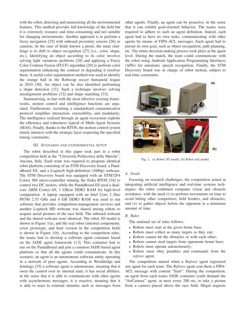
shown in Figure 1(a), and the real robot (internal components,
cover prototype, and final version in the competition field)
is shown in Figure 1(b). According to the competition rules,
the teams had to develop a software agent container based
on the JADE agent framework [13]. This container had to
run on the PandaBoard and join a common JADE-based agent
platform so that all the agents could communicate. In this
scenario, an agent is an autonomous software entity operating
in a network of peer agents. According to Wooldridge and
Jennings [35] a software agent is autonomous, meaning that it
owns the control over its internal state; it has social abilities,
in the sense that it is able to communicate with other agents
with asynchronous messages; it is reactive, meaning that it
is able to react to external stimulus such as messages from
other agents. Finally, an agent can be proactive, in the sense
that it can exhibit goal-oriented behavior. The teams were
required to adhere to such an agent definition. Indeed, each
agent had to have its own tasks, communicating with other
agents by means of FIPA-ACL messages. Each agent had to
pursue its own goal, such as object recognition, path planning,
etc. The entire decision-making process took place at the agent
level. During the match, the team could communicate with
the robot using Android Application Programming Interfaces
(APIs) for automatic speech recognition. Finally, the STM
Discovery board was in charge of robot motion, subject to
real-time constraints.
Fig. 1. (a) Robot 3D model; (b) Robot real model.
A. Goals
Focusing on research challenges, the competition aimed at
integrating artificial intelligence and real-time systems tech-
niques: the robot combined computer vision and obstacle
avoidance, with the need (i) to perform movements on time to
avoid hitting other competitors, field borders, and obstacles,
and (ii) to gather objects before the opponent in a minimum
amount of time.
B. Rules
The minimal set of rules follows:
• Robots must start at the given home base;
• Robots must collect as many targets as they can;
• Robots cannot hit the obstacles or with each other;
• Robots cannot steal targets from opponents home base;
• Robots must operate autonomously;
• Robots must obey penalties and commands from the
referee agent.
The competition started when a Referee agent registered
one agent for each team. The Referee agent sent them a FIPA-
ACL message with content “Start”. During the competition,
an agent from each teams JADE container could demand the
“AirCamera” agent, at most every 200 ms, to take a picture
from a camera placed above the race field. Illegal requests

were refused. The robot not following the rules received
a penalty from the Referee agent, in the form of a FIPA-
ACL message with content “penalty”. After receiving such
a message, the agent in the robots agent container had to stop
for a specified amount of time. The Referee ended the round
sending an FIPA-ACL message with content “Stop”.
C. Race field
The competition took place in a real race field. A 3D and
2D view of the race field model is shown in Figure 2. The
field’s ground was black with the borders of the field and the
obstacles in red. The yellow and purple squares at opposite
corners were the robots’ home bases where they had to bring
the blue and green cardboard parallelepipeds, the objects,
collected in the field. The competition organizers set different
objects and obstacle maps for each round.
Fig. 2. Competition scenario: (a) Field 3D model; (b) Real Fild side view;(c) Real Field airCamera view.
IV. THE PROPOSED SOLUTION
This section presents the proposed solution and its com-
ponents, motivating the strategic choices. The strategy is
to delegate and distribute duties among agents in order to
maximize parallelism and agents’ specialization on specific
functions. Each agent has specific functionalities that can be
triggered by time, specific agents’ goals, reception of specific
requests, or specific events. Such functionalities are coded as
combinations of JADE’s behaviors (waker, cyclic ticker, and
oneShot) [13]. The first step is to require the field image
Figure 2(c) to the AirCamera agent, which provides an aerial
image of the field. There is a time limit of 200 ms on
consecutive requests placed on AirCamera and those that come
in a shorter time period are rejected. Once processed, the
image provides the robot’s position and orientation and the
obstacles positions. The second step is to find the target and
determine the path needed to reach it. Recalling that software
agents interact by exchanging messages, Figure 3 shows the
proposed agent system and interactions between them. Agents
are distributed among an Android smartphone, a robot, and a
laptop is in charge of the competition control.
Fig. 3. Agents Framework: organization and interactions.
Referring to Figure 3, the Vocalist is the agent working
on the mobile phone. It makes the communication between
the team and the autonomous robot possible, translating the
human (vocal) indications into actual messages, thus activating
the interaction V1:
• V1: target values and the “ready state” (from the team)
have to be communicated to the Reader agent in order to
start the robot.
When the Reader receives messages from the Vocalist, it
reacts performing interactions RED1, RED2 and RED3:
• RED1: information about target values, which impacts
on target selection, is sent to the PathSetter agent, along
with both the “ready state” and the actual “start race”.
This means that the race is started.
• RED2: if the Reader receives motion commands from
a human, it sends them to the DriveMeCrazy agent in
charge of communicating with the motion system.
• RED3: all the information received is sent to the Loggeragent in charge of publishing them in the web page
depicted in Figure 4.
As described in Section III, the match actually starts when
the Referee agent communicates to the robots (in the ready
status) the actual “start race”. The Scout agent is in charge

of exchanging information with Referee and AirCamera. The
start of the match generates the message REF1.
• REF1: is a single message that communicates to the robot
that the match has started.
This event triggers the following interactions:
• S1: Scout is allowed to ask an image from AirCamera at
most every 200 ms. If the request is accepted, AirCamerasends Scout a message with an image. Otherwise, it will
notify an error.
• S2: saves the image and notifies PathSetter.
• S3: sends match status, info and behaviours to Logger.
PathSetter is in charge of visual processing and path-finding.
This agent is characterized by a ticker behavior which activates
a set of tasks every 200 ms. The image processing algorithm
is composed of multi-step activities: cell decomposition, robot
detection, target identification, target selection and obstacle
detection. This algorithm is presented in Section IV-B. When
path calculation is finished, PathSetter sends the messages PS1
and PS2:
• PS1: communicates to DriveMeCrazy the set of move-
ments needed to reach the target.
• PS2: communicates to Logger the robot’s position, target
position and path.
When DriveMeCrazy receives PS1, it performs the interac-
tions DMC1 and DMC2:
• DMC1: transfers motion commands to the STM Discov-
ery board which is in charge of the DC motors.
• DMC2: receives information from the STM Discovery
board about the motors’ status, and then sends them to
Logger.
If an error is detected with respect to the path to follow, the
interaction DMC3 is activated.
• DMC3: DriveMeCrazy communicates variations with re-
spect to the expected path (e.g. the robot has been hit
by the opponent, an error happened during the motion
control, etc.), requiring a new input from PathSetter.
If Referee sends “penalty” or “end game” commands, inter-
actions S4 and S5 are activated.
• S4: PathSetter does not need to compute until a new order
is received or time penalty is expired.
• S5: Motor “stop” is immediately required.
A. Vocal Interaction
The system makes use of the Google APIs to perform
speech recognition. The Vocalist agent, Figure 3, runs on an
Android smartphone by means of the JADE-LEAP add-on
for JADE [13]. JADE-LEAP allows to create a lightweight
container (the “front-end”) on smartphones and embedded de-
vices, providing a basic JADE run-time environment; advanced
JADE functions are delegated to a “back-end” container run-
ning on a remote server. When all the needed functionalities
are activated, the Vocalist agent is created. As a regular
agent, Vocalist is registered into the JADE Agent Management
System, which is automatically provided by the JADE main
Fig. 4. Robot Log Web Interface.
container running on the robot. Vocalist acts as a listener in an
app to control the robot, and sends instructions to the Readeragent. Thus, the vocalist agent is an interface between the
human operators (the members of the team) and the robot con-
trol. Figure 5 shows the app interfaces. Commands are divided
into two categories. The mandatory commands, Figure 5(a)
are: “stop”, “Command List”, “Send a command”. In each
competition round, before the actual “start race”, each team
was requested to vocally communicate the color of the targets
to be gathered by the robot. Hence, during the competition,
the mobile app did not interfere with the autonomous systems,
even if optional commands (“start”, “stop”, “go home”, “left”,
“right”, “step forward”, “step back”), usable only in case of
emergency, were implemented.
B. Computer Vision
As said before, during the match, the Scout agent sends
every aerial image of the field received from the airCamerato the PathSetter, which is in charge of managing the computer
graphic. The image processing makes use of the OpenCV
library (a set of tools used for the computer vision [36]).
cvBlob is a subset of libraries that allows a real-time image
processing of moving objects [37]. In the computer vision
domain, a blob is a group of connected pixels with the same
logical state.
The first step of the analysis requires to identify robot
position and orientation, through a special marker on the top
of the robot. To find the marker, parameters such as minimum
and maximum dimensions of the blob area, and the HSV
color code need to be set. Since the field illumination is not
homogeneous, to identify the marker in all the fields, a range
of HSV values, rather than a single color code, need to be
set. The HSV range tuning is shown in Figure 6(a). In order
to facilitate the understanding of the tuning effectiveness, a
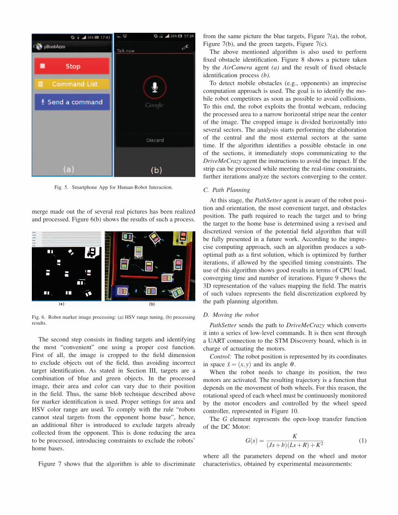
Fig. 5. Smartphone App for Human-Robot Interaction.
merge made out the of several real pictures has been realized
and processed. Figure 6(b) shows the results of such a process.
Fig. 6. Robot marker image processing: (a) HSV range tuning, (b) processingresults.
The second step consists in finding targets and identifying
the most “convenient” one using a proper cost function.
First of all, the image is cropped to the field dimension
to exclude objects out of the field, thus avoiding incorrect
target identification. As stated in Section III, targets are a
combination of blue and green objects. In the processed
image, their area and color can vary due to their position
in the field. Thus, the same blob technique described above
for marker identification is used. Proper settings for area and
HSV color range are used. To comply with the rule “robots
cannot steal targets from the opponent home base”, hence,
an additional filter is introduced to exclude targets already
collected from the opponent. This is done reducing the area
to be processed, introducing constraints to exclude the robots’
home bases.
Figure 7 shows that the algorithm is able to discriminate
from the same picture the blue targets, Figure 7(a), the robot,
Figure 7(b), and the green targets, Figure 7(c).
The above mentioned algorithm is also used to perform
fixed obstacle identification. Figure 8 shows a picture taken
by the AirCamera agent (a) and the result of fixed obstacle
identification process (b).To detect mobile obstacles (e.g., opponents) an imprecise
computation approach is used. The goal is to identify the mo-
bile robot competitors as soon as possible to avoid collisions.
To this end, the robot exploits the frontal webcam, reducing
the processed area to a narrow horizontal stripe near the center
of the image. The cropped image is divided horizontally into
several sectors. The analysis starts performing the elaboration
of the central and the most external sectors at the same
time. If the algorithm identifies a possible obstacle in one
of the sections, it immediately stops communicating to the
DriveMeCrazy agent the instructions to avoid the impact. If the
strip can be processed while meeting the real-time constraints,
further iterations analyze the sectors converging to the center.
C. Path Planning
At this stage, the PathSetter agent is aware of the robot posi-
tion and orientation, the most convenient target, and obstacles
position. The path required to reach the target and to bring
the target to the home base is determined using a revised and
discretized version of the potential field algorithm that will
be fully presented in a future work. According to the impre-
cise computing approach, such an algorithm produces a sub-
optimal path as a first solution, which is optimized by further
iterations, if allowed by the specified timing constraints. The
use of this algorithm shows good results in terms of CPU load,
converging time and number of iterations. Figure 9 shows the
3D representation of the values mapping the field. The matrix
of such values represents the field discretization explored by
the path planning algorithm.
D. Moving the robot
PathSetter sends the path to DriveMeCrazy which converts
it into a series of low-level commands. It is then sent through
a UART connection to the STM Discovery board, which is in
charge of actuating the motors.
Control: The robot position is represented by its coordinates
in space x = (x,y) and its angle θ .
When the robot needs to change its position, the two
motors are activated. The resulting trajectory is a function that
depends on the movement of both wheels. For this reason, the
rotational speed of each wheel must be continuously monitored
by the motor encoders and controlled by the wheel speed
controller, represented in Figure 10.
The G element represents the open-loop transfer function
of the DC Motor:
G(s) =K
(Js+b)(Ls+R)+K2(1)
where all the parameters depend on the wheel and motor
characteristics, obtained by experimental measurements:

(a) (b) (c)
Fig. 7. Output of the graphical elaboration: (a) Blue target identification, (b) Marker identification and (3) Green target identification.
Fig. 8. Obstacles identification: (a) aereal field image, (b) HSV range tuning.
Fig. 9. Battle field discretization: a 3D model.
• J = 0.188(kg ·m2): moment of inertia of the rotor.
• b = 0.05(N ·m · s): motor viscous friction constant.
• K = 0.7639(V/rad/sec)or(N · m/Amp): electromotive
force constant, equal to the motor torque constant.
• R = 4.5(Ohm): electric resistance.
• L = 0.587(H): electric inductance.
The speed controller Q is implemented by a proportional-
Q G+Θref.
Θ.+
-
e
W
Fig. 10. Wheel Speed Controller.
integral-derivative (PID) regulator. A preliminary controller
tuning has been performed by using the Ziegler-Nichols rules,
and then the obtained parameters were finely tuned by exper-
imental tests.
An error on the actual position can arise despite the wheel
speed controllers. This happens because the robot position
depends on the speed of both wheels, but the two speed
controllers are independent of each other. Another control loop
is added to solve this problem, as shown in Figure 11. This
loop uses the module S to calculate the robot position based
on the two wheels speeds and sends it back to the controller
module C, which adapts the speeds of the wheels according
to the desired trajectory.
Depending on the scenario, the agent DriveMeCrazy ex-
ploits different behaviors to interact with C:
• Re fcmd : handles the requests performed by the referee.
• Ucmd : manages the users’ requests interacting with C and
Pcmd .
• Pcmd : sends the path to be followed to the autopilot.

DriveMeCrazy
Pcmd
Ucmd
A
Mcmd
R
cmd
cmd
D
{ W1
W2
S
Wheel ControlCommander (C)
2
2
2
2
2cmdRef
Fig. 11. Motion Controller.
E. Tasks
The software has been organized in the following tasks:
• W1, W2: perform proportional controls on the speed of
the associated wheel.
• S: detects the wheels movements and calculates the robot
position.
• The controller C decides the speed of each wheel. This
module includes the following tasks:
– Acmd : is the autopilot that depending on the current
sensed position and the path received by Pcmd actu-
ates the motors. Furthermore, such autopilot sends
messages back to the DriveMeCrazy agent to notify
eventual errors or new request.
– Mcmd : handles user manual commands.
– Rcmd : manages requests from the referee, in particu-
lar the stop command.
The C module internally chooses - with a multiport switch,
whose control input is decided by the D module - the correct
reference speeds among the speeds proposed by the tasks Acmd ,
Mcmd and Rcmd , based on their availability and relevance. The
decisions taken by Rcmd are the most important because the
referee must be able to stop the robot regardless of other
commands or the internal robot status. Mcmd is more important
than Acmd because the user commands have higher value than
the robot’s own decisions. If none of the mentioned tasks
proposes a command, then the robot stops.
Mcmd and Rcmd are sporadic tasks, while Acmd , S, W1 and
W2 are periodic tasks.
Tasks are assigned fixed priorities and scheduled according
to the Rate Monotonic (RM) algorithm [38].
The total number of tasks, identified with n, is equal to
6. By defining the computational time of the generic task ias Ci, the activation period as Ti and the utilization factor as
Ui =Ci/Ti, the schedulability test can be performed by using
the Liu and Layland sufficient condition [38]:
n
∑i=1
Ui ≤ n(
21/n −1). (2)
The most time-critical task is S because its correct timing
behavior is required in order to preserve a good approximation
of the robot position. Supposing that each encoder has a
precision of ne(ppr) and the maximum rotational speed of
each wheel is wmax(rpm), in order to preserve the accuracy of
the encoders, the task S must have a maximum period defined
by the following relation
TS <1
wmax ·ne·60(s). (3)
Even though Mcmd and Rcmd are sporadic, it is possible to
assume a minimum inter-arrival time to verify the system’s
schedulability. Those tasks manage interactions with humans,
so a period of 50 ms is enough to guarantee a responsive user-
perceived system.The minimum periods of W1, W2 and Acmd are calculated
by finding their maximum utilization factors that preserve the
task set schedulability.
V. EXPERIMENTAL RESULTS
This section presents the results obtained from the real
experimental setup outlined above. Experiments are conceived
to test compliance with time constraints at each level of the
software architecture, from the high-level decision making to
the low-level motion control algorithms. Communications with
services that can be used by more than one robot are also
tested, taking into account their mutual-exclusive usage.The interaction between the Scout and the AirCamera agents
is depicted in Figure 12. This interaction, is not cooperative but
competitive, in the sense that the AirCamera agent arbitrates
the access to a shared resource. This means that when more
than one agent tries to communicate with AirCamera the
response can be delayed, as highlighted in the experimental
results reported in Table I.When a single Scout agent interacts with AirCamera, the
message exchange (consisting of a request message, the image
acquisition, and a response message) lasts on the average 673.6
ms, ranging from 634 ms in the best case and 1514 ms in
the worst case. Such values are obtained on 1000 iterations.
Execution times for each step are listed in Table I. When
more than one Scout agent tries to communicate with the
AirCamera, the time to serve the request arise due to the
waiting time needed to serve the queued previous requests.
For example, in such a scenario, the second agent being served
experiences a total waiting time which is the sum of the time
needed to serve the other request and the time needed to
serve its request. This means that the interaction timing nearly
doubles. Indeed, experimental measurements for this second
scenario outlined above confirmed this. The message exchange
in this scenario lasts on average 1330.7 ms while the best case
is 1260 ms and the worst case is 3004 ms. Since the image
from the AirCamera is used to plan a strategy (identifying
the target and planning the path), such a worst-case scenario
means that three seconds might pass before the autonomous
robots can change its strategic plans. However, it does not
affect the reacting and moving capabilities of the robot, which
are based on the last deliberated plan. Moreover, moving
obstacles can be detected by the onboard frontal webcam for
which there are no competing agents.

Scout AirCamera
requiring picture
sending picture
processing request
accessing camera
taking picture
encoding picture
saving picture
graphical elaboration
path finding
Fig. 12. Scout-AirCamera interaction.
Once the image is received, agents have to decode, save and
process it in order to deliberate the target and identify the set
of commands to reach it. This process makes use of computer
vision and pathfinding algorithms, as outlined above. Table II
reports the processing time derived on 1000 executions of such
tasks. The amount of time required to determine the path to
follow is on average 51.6 ms, which reduces to 32 ms in the
best case and peaks at 378 ms in the worst case.
Regarding the low-level motion control systems, worst-
case execution times (WCET) for motion control tasks were
experimentally measured and are reported in Table III.
In the experimental setup, each wheel is able to rotate
at a maximum speed of 150(rpm), while the encoder has
a precision of 4480(ppr). Using Equation (3), the resulting
period is TS ≤ 89.28 μs.
TABLE ISCOUT-AIRCAMERA MESSAGE EXCHANGE TIMING
best casetime (ms)
worst casetime (ms)
averagetime (ms)
send picture request 8 22 16.5
take and encodepicture
580 1228 602.4
send picture 46 263 54.7
TABLE IIDELIBERATION PROCESSES TIMING
best casetime (ms)
worst casetime (ms)
averagetime (ms)
saving 27 359 39.2
compute visionelaboration
3 11 8.3
pathfinding 2 8 4.1
TABLE IIITASK’S EXPERIMENTAL WCET
Task WCET (μs)
W1, W2 24.4S 16.3
Acmd 40.9Mcmd , Rcmd 19.9
Applying equation (2) to the system’s taskset, we have:
CW1
TW1+
CW2
TW2+
CS
TS+
CAcmd
TAcmd
+CMcmd
TMcmd
+CRcmd
TRcmd
≤ n(
21/6 −1)
(4)
The dynamic of the outer control loop must be slower than
the dynamic of the internal control loop to allow the internal
loop to reach stability. For this reason and due to the equality
of TW1 and TW2 the period is taken as TWi = TW1 = TW2 =20 ·TAcmd . Performing this substitution and bringing the known
terms to the right, the previous equation becomes:
TWi ≥ CAcmd/20+CW1 +CW2
n(21/n −1
)− CSTS
− CMcmdTMcmd
− CRcmdTRcmd
. (5)
The previous equation can be solved for periods substituting
numerical values. Making some pessimistic approximations,
the resulting periods are: TW1 = TW2 = 100 μs and TAcmd =2 ms.
From a functional point of view, the system resulted to be
effective and efficient. In all the experimental runs, the robot
was able to identify itself, the targets and all the obstacles.
Furthermore, the pathfinding heuristic obtained the 100% of
success, meaning that the path connecting the robot and its
target was always identified, if existing. Considering the exe-
cuted experiments, 70% of the identified paths were identical
to the optimal ones. With respect to the most known A* [5],
D* [39] and Dijkstra algorithms [5], the proposed algorithm
achieved a substantial gain in terms of computational load,
converging time and sub-optimal solution quality.
VI. CONCLUSIONS
This paper presented an autonomous mobile robot designed
to collect objects in a competition arena, interact with humans,
software agents and other robots, in a given amount of time. AI
and real-time methods and techniques were combined together
to obtain a robot able to autonomously perform intelligent
actions under real-time constraints. A two-level software archi-
tecture was used, in which the high-level agent-based software
was in charge for decision-making and communication while
a low-level real-time software controlled motion and reacted
to environmental changes.
The solution described in the paper highlights the strength
of a modular approach solving complex and very different
problems, like image processing, path planning, and robot
control in a competitive scenario. cvBlob seems to be a good
choice with respect to real-time constraints, performing image
recognition tasks fairly well even in the worst-case scenario

when used on the embedded board on the robot. On the other
hand, delays due to concurrent access to shared resources and
the amount of messages exchanged between software agents
in response to a change in the environment seems to affect
the performance of the system. From a functional point of
view, software agents are able to achieve their goals on a
regular basis, thus placing the real-time motion control system
in better operational condition. However, software agents lack
a mechanism to take into account real-time constraints, thus
making it difficult to coordinate them during transient overload
conditions.Making software agents aware of real-time requirements
seems to be a good research challenge on its own that can
open the way to real-time agent-oriented programming. As
a first step, Real-Time Publish-Subscriber (RTPS) protocol
could be integrated into agent-based systems, thus providing
them with a real-time communication protocol integrated into
the distributed nature of the multi-agents paradigm.
VII. ACKNOWLEDGMENT
A special thanks is due to Stephanie Sadler, Luca
Panebianco, Silvia Fichera, and the team members: Lorenzo
Volponi, Davide Liberato and Luca Severini.
REFERENCES
[1] T. Braunl, “Research relevance of mobile robot competitions,” IEEERobotics & Automation Magazine, vol. 6, no. 4, pp. 32–37, 1999.
[2] M. Veloso and P. Stone, “Individual and collaborative behaviors in ateam of homogeneous robotic soccer agents,” in Multi Agent Systems,1998. Proceedings. International Conference on, 1998.
[3] D. Calvaresi, A. Claudi, A. F. Dragoni, E. Yu, D. Accattoli, andP. Sernani, “A goal-oriented requirements engineering approach for theambient assisted living domain,” in Proceedings of the 7th InternationalConference on PErvasive Technologies Related to Assistive Environ-ments. ACM, 2014, p. 20.
[4] A. Manzalini, “A think tank on softwarization (from sdn, nfv,cloud-edge-fog computing...to 5g).” [Online]. Available: http://ieee-sdn.blogspot.it/
[5] S. Russell and P. Norvig, Artificial Intelligence: A Modern Approach,3rd ed. Prentice Hall, 2009.
[6] G. Weiss, Multiagent systems: a modern approach to distributed artifi-cial intelligence. MIT press, 1999.
[7] A. FIPA, “Message structure specification. foundation for intelligentphysical agents, 2000,” pp. 09–29, 2004.
[8] A. Schuldt, “Multiagent coordination enabling autonomous logistics,”KI-Kunstliche Intelligenz, vol. 26, no. 1, pp. 91–94, 2012.
[9] F. Ingrand and M. Ghallab, “Deliberation for autonomous robots: Asurvey,” Artificial Intelligence, 2014.
[10] D. Montemerlo, N. Roy, and S. Thrun, “Perspectives on standardizationin mobile robot programming: the carnegie mellon navigation (carmen)toolkit,” in Intelligent Robots and Systems, 2003. (IROS 2003). Proceed-ings. 2003 IEEE/RSJ International Conference on, vol. 3, Oct. 2003.
[11] A. Brooks, T. Kaupp, A. Makarenko, S. Williams, and A. Oreback,“Towards component-based robotics,” in Intelligent Robots and Systems,2005. (IROS 2005). 2005 IEEE/RSJ International Conference on, Aug.2005.
[12] M. Quigley, K. Conley, B. Gerkey, J. Faust, T. Foote, J. Leibs,R. Wheeler, and A. Y. Ng, “Ros: an open-source robot operating system,”in ICRA workshop on open source software, vol. 3, 2009.
[13] F. L. Bellifemine, G. Caire, and D. Greenwood, Developing multi-agentsystems with JADE. John Wiley & Sons, 2007.
[14] N. Muscettola, G. A. Dorais, C. Fry, R. Levinson, C. Plaunt, andP. Norvig, “A unified approach to model-based planning and execution,”2000.
[15] C. McGann, F. Py, K. Rajan, H. Thomas, R. Henthorn, and R. McEwen,“A deliberative architecture for auv control,” in Robotics and Automa-tion, 2008. ICRA 2008. IEEE International Conference on, 2008.
[16] N. Muscettola, P. P. Nayak, B. Pell, and B. C. Williams, “Remote agent:To boldly go where no ai system has gone before,” Artificial Intelligence,vol. 103, 1998.
[17] S. Behnke, “Robot competitions-ideal benchmarks for robotics re-search,” in Proc. of IROS-2006 Workshop on Benchmarks in RoboticsResearch, 2006.
[18] T. Wisspeintner, T. Van Der Zant, L. Iocchi, and S. Schiffer, “Robocup@home: Scientific competition and benchmarking for domestic servicerobots,” Interaction Studies, vol. 10, 2009.
[19] S. Schiffer, A. Ferrein, and G. Lakemeyer, “Caesar: an intelligentdomestic service robot,” Intelligent Service Robotics, vol. 5, 2012.
[20] M. Rioux, “Laser range finder based on synchronized scanners,” Appliedoptics, vol. 23, 1984.
[21] T. Kotoku, “A predictive display with force feedback and its applicationto remote manipulation system with transmission time delay,” in Intel-ligent Robots and Systems, 1992., Proceedings of the 1992 lEEE/RSJInternational Conference on, vol. 1, 1992.
[22] V. Lumelsky and T. Skewis, “A paradigm for incorporating visionin the robot navigation function,” in Robotics and Automation, 1988.Proceedings., 1988 IEEE International Conference on, 1988.
[23] E. Garcia and P. G. De Santos, “Mobile-robot navigation with completecoverage of unstructured environments,” Robotics and AutonomousSystems, vol. 46, 2004.
[24] R. N. De Carvalho, H. Vidal, P. Vieira, and M. Ribeiro, “Completecoverage path planning and guidance for cleaning robots,” in IndustrialElectronics, 1997. ISIE’97., Proceedings of the IEEE InternationalSymposium on, vol. 2, 1997.
[25] K.-T. Song and J.-C. Tai, “Fuzzy navigation of a mobile robot,” in In-telligent Robots and Systems, 1992., Proceedings of the 1992 lEEE/RSJInternational Conference on, vol. 1, 1992.
[26] K. Samsudin, F. A. Ahmad, and S. Mashohor, “A highly interpretablefuzzy rule base using ordinal structure for obstacle avoidance of mobilerobot,” Applied Soft Computing, vol. 11, 2011.
[27] A. Torralba, K. P. Murphy, W. T. Freeman, and M. A. Rubin, “Context-based vision system for place and object recognition,” in ComputerVision, 2003. Proceedings. Ninth IEEE International Conference on,2003.
[28] G. K. Kloss, H. Shin, and N. H. Reyes, “Dynamic colour adaptation forcolour object tracking,” in Image and Vision Computing New Zealand,2009.
[29] N. Reyes and C. Messom, “Identifying colour objects with fuzzy colourcontrast fusion,” in 3rd International conference on computationalintelligence, robotics and autonomous systems, and FIRA roboworldcongress, 2005.
[30] J.-S. Chiang, C.-H. Hsia, and H.-W. Hsu, “A stereo vision-based self-localization system,” Sensors Journal, IEEE, vol. 13, 2013.
[31] H. Murase and S. K. Nayar, “Visual learning and recognition of 3-d objects from appearance,” International journal of computer vision,vol. 14, 1995.
[32] D. Wolter, Spatial representation and reasoning for robot mapping: ashape-based approach. Springer, 2008.
[33] S. Belongie, J. Malik, and J. Puzicha, “Shape matching and object recog-nition using shape contexts,” Pattern Analysis and Machine Intelligence,IEEE Transactions on, vol. 24, 2002.
[34] P. Gai, E. Bini, G. Lipari, M. Di Natale, and L. Abeni, “Architecturefor a portable open source real-time kernel environment,” 2000.
[35] M. Wooldridge and N. R. Jennings, “Intelligent agents: theory andpractice,” The Knowledge Engineering Review, vol. 10, pp. 115–152,1995.
[36] G. Bradski and A. Kaehler, Learning OpenCV: Computer vision withthe OpenCV library. ” O’Reilly Media, Inc.”, 2008.
[37] G. L. GPL, “cvblob — archive.” [Online]. Available:https://code.google.com/archive/p/cvblob/
[38] G. C. Buttazzo, Hard Real-Time Computing Systems: PredictableScheduling Algorithms and Applications, 3rd ed. Springer PublishingCompany, Incorporated, 2011.
[39] A. Stentz, “Optimal and efficient path planning for partially-knownenvironments,” in Robotics and Automation, 1994. Proceedings., 1994IEEE International Conference on. IEEE, 1994, pp. 3310–3317.


![Intro Cpp.ppt [modalità compatibilità]retis.sssup.it/~giorgio/slides/cbsd/DiNatale1-6p.pdf · Microsoft PowerPoint - Intro_Cpp.ppt [modalità compatibilità] Author: Giorgio Created](https://static.fdocuments.us/doc/165x107/602c0f667ad600134f7d3a31/intro-cppppt-modalit-compatibilitretissssupitgiorgioslidescbsddinatale1-6ppdf.jpg)