A Floorplan-Aware Dynamic Inductive Noise Controller for Reliable Processor Design Fayez Mohamood...
23
A Floorplan-Aware Dynamic Inductive Noise Controller for Reliable Processor Design Fayez Mohamood Michael Healy Sung Kyu Lim Hsien-Hsin “Sean” Lee School of Electrical and Computer Engineering Georgia Institute of Technology
-
Upload
debra-parsons -
Category
Documents
-
view
215 -
download
1
Transcript of A Floorplan-Aware Dynamic Inductive Noise Controller for Reliable Processor Design Fayez Mohamood...

A Floorplan-Aware Dynamic Inductive Noise Controller for Reliable Processor DesignFayez MohamoodMichael HealySung Kyu LimHsien-Hsin “Sean” Lee
School of Electrical and Computer Engineering Georgia Institute of Technology

2
Presentation Overview• Motivation
• Inductive Noise Variants
• Floorplan aware dynamic di/dt controller
• Simulation Results
• Conclusion
3
VoltageRegulator
CHIP
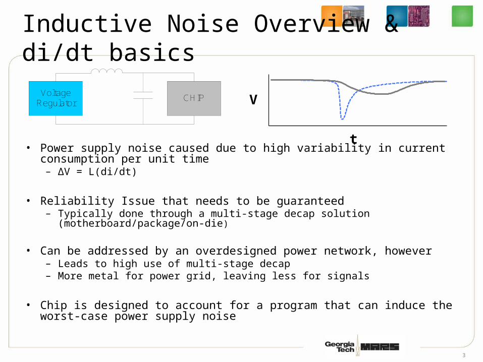
Inductive Noise Overview & di/dt basics
• Power supply noise caused due to high variability in current consumption per unit time– ΔV = L(di/dt)
• Reliability Issue that needs to be guaranteed– Typically done through a multi-stage decap solution
(motherboard/package/on-die)
• Can be addressed by an overdesigned power network, however– Leads to high use of multi-stage decap – More metal for power grid, leaving less for signals
• Chip is designed to account for a program that can induce the worst-case power supply noise
t
V

4
Why Noise and Why Now?• More active devices on chip
– Higher power consumption
• Exponential increase in current consumption– Intel reports 225% increase per unit area per generation
• Device size miniaturization leads to lower operating voltages– Lower noise margins
• Multi-core trend can exacerbate di/dt issues
• Aggressive power saving techniques – Clock-gating
Source: Intel Technology Journal
Volume 09, Issue 04 Nov 9,2005

5
Worst-case Design Inefficiency
Is the design reliable? Is the design reliable? YES
Ship IT !Ship IT !
NO
Worst-case DesignWorst-case Design
• Post-Design Decap Allocation Consumes chip real-estate Contributes to leakage
• Finer clock gating domains Increases design complexity
• Ex: Design package/heatsink for worst-case thermal profile
Average-case DesignAverage-case Design
• Static control through physical design
• Dynamic di/dt control for worst case
• Ex: DTM (Dynamic Thermal Management) Thermal diode monitoring to throttle CPU activity
NO
A one-size-fits-all approach is needed

6
Inductive Noise
Inductive Noise Classes
Low – Mid Frequency High Frequency
• Caused by global transient• Typically in the 20-100 MHz range• Does not require instantaneous response
• Mostly due to local transient (clock-gating)• di/dt effects over 10s of cycles• Instantaneous response critical
• Low impedance path between power supply and package• Handled by package/bulk decap
• Low impedance path between cells and power supply nodes• Handled by on-die decap
Characteristics
Mitigation
• M. Powell, T.N. Vijaykumar (ISCA’03/’04)
• R. Joseph, Z. Hu, M. Martonosi (HPCA ‘03/’04)
• K. Hazelwood, D. Brooks (ISLPED ‘04)
• M. Powell, T.N. Vijaykumar (ISLPED ’03)

7
di/dt from a Microarchitectural Perspective• Noise characteristics reflect program behavior
– Static characteristics like the FU usage– Dynamic characteristics like cache misses
• Power Viruses characterize noise limits on a chip
– A program that alternates between extremely low to extremely high levels of activity (ILP for example)
• An effective high frequency dynamic di/dt controller
– Guarantees that a power virus will not result in integrity issues
– Is acutely aware of the module activity and floorplan– Provides a good tradeoff between noise vs. performance

8
Decay-Counter Based Clock Gating
• When can a module be reliably gated on and off?• How can module activity be monitored with ultra-
low overhead?• How can we fine-tune clock-gating activity?• Decay Counters present an effective means
L1 Instruction Cache
0
1
1 51 101 151
Cycles
Branch Predictor
0
1
1 51 101 151
Cycles
Integer ALU
0
1
1 51 101 151
Cycles

9
Floorplan-aware dynamic di/dt controller
• Decay counters alone are not floorplan-aware• Can improve the current profile, but not guarantee
current demand• Simultaneous gating needs to be controlled• A “queue-based” di/dt control mechanism can
achieve all of the above.
bpred
I$
Module State/Transition WeightI-Cache ON 3Bpred OFF ON 2ALU-1 OFF ON 1ALU-2 OFF 1ALU-3 OFF 1
Module DecayI-Cache 4Bpred 16ALU-1 1ALU-2 0ALU-3 0
ALU InstructionPre-decoder
&0
0
0
&0
0
0
&0
0
0
To Pipeline Stall LogicIn this illustration, the availability of the I-Cache &
Bpred determine if the IF stage can proceed.Similar pipeline throttling logic is needed for every
pipeline -stage based on necessary modules.
Clock-Gate Enable SignalAs shown, the queue drivers pre-wired clock-gatelogic signals for modules in the same power-pin
domain.
Pre-emptive ALU PredecodeThe instruction pre-decoder overrides the
decay counters when necessary to preventunnecessary ALU gating.
ALU2
ALU1
ALU3
Module Decay Counters di/dt Queue Controller
Power-Pin
2D/3D Chip FloorplanAccess Pattern
Feedback
Pre-wired Clock-Gaters
Pipeline Stall LogicPre-emptive ALU gating
Chip Floorplan

10
Total Weight = 2 <
Threshold = 3
Example Illustration
• Cluster with three modules in same power pin domain
• Assume permissible gating threshold 3 Amps• ONOFF is a negative switch• OFFON is a positive switch
I$
LSQ
B-Pred
Module Decay Weight
State
I$ 2
LSQ 3
B-Pred 13
ON
ON
ON
3
3
2
2
1
1
0
0
ON OFF
ON OFFOFF
OFF
Gate OFF LSQ
Gate OFF I$Fetch BlockedRequest for LSQ
&B-Pred Decay 0
OFF ON
210 ONOFFOFF
ON
Re-sizeableSliding Window
Pre-wired Clock Gating Signal
di/dt Queue Controller
Floorplan Cycle: 12354760
I$ and LSQ violates 3 Amp Threshold!3

11
Experimental Setup
Parameters ValuesFetch/Decode Width 8-wide
Issue/Commit Width 8-wide
Branch Predictor Combining 16K-Entry MetatableBimodal: 16K Entries
2-Level: 14 bit BHR, 16K entry PHT
BTB 4-way, 4096 sets
L1 I$ & D$ 16KB 4-Way 64B Line
I-TLB & D-TLB 128 Entries
L2 Cache 256KB, 8-way, 64B Line
L1/L2 Latency 1 cycle/6 cycles
Main Memory Latency 500 cycles
LSQ Size 64 entries
RUU Size 256 entries

12
Full Chip Current Analysis
• Low ILP benchmark – 164.mcf• Decay counter maintains an optimal power envelope• Smoothens the down-ramp
mcf Current Profile
0
5
10
15
20
25
30
35
1 501 1001 1501 2001 2501 3001 3501 4001 4501
Cycles
Cu
rren
t (a
mp
s)
Ideal Clock-Gating Decay Counter Clock-Gating
mcf Current Profile (Zoomed View)
0
5
10
15
20
25
30
35
1 51 101 151
Cycles
Cu
rren
t (a
mp
s)
Ideal Clock-Gating Decay Counter Clock-Gating

13
Queue Current Analysis
• Low ILP benchmark – 164.mcf• Queue prevents simultaneous gating • Alleviates both abrupt up/down ramps
mcf - Queue 1 Current Profile
0
1
2
3
4
5
6
7
1 51 101 151 201
Cycles
Cu
rren
t (a
mp
s)
Baseline High Frequency di/dt Controller
mcf - Queue 2 Current Profile
0
1
2
3
4
1 51 101 151
Cycles
Cu
rren
t (a
mp
s)
Baseline High Frequency di/dt Controller

14
Current Variability
• Reduces current variability by 7x average• All benchmarks are consistently below 0.5
amps/cycle
Current Variability
0
0.5
1
1.5
2
2.5
3
bzip
craf
ty eon
gap
gzip
perl
pars
ertw
olf
amm
p
appl
uap
si art
equa
ke
face
rec
fma3
d
galg
el
luca
sm
esa
mgr
id
sixtra
cksw
im
wupwise
INT M
ean
FP Mea
n
del
ta-I
per
cyc
le
Baseline HF di/dt Controller

15
Thermal Analysis
• Hotspot Initial Temperature 300K• Avg. temperature increase of 3.15K
Thermal Analysis
308
310
312
314
316
318
320
322
324
326
328
330
Bpred Btb Ls
q Irf Frf Il1 Itlb Dl1 Dl2Dtlb ru
ualu
1alu
2alu
3alu
4alu
5alu
6alu
7alu
8fa
lu1fa
lu2fa
lu3fa
lu4
Te
mp
erat
ure
(K
)
Baseline HF di/dt Controller

16
Performance Analysis
• Baseline (full-speed) vs. didt throttling• Avg. IPC degradation of 4.0%
Performance Analysis
0.00%
1.00%
2.00%
3.00%
4.00%
5.00%
6.00%
7.00%
8.00%
9.00%
10.00%
bzip
craft
yeo
nga
pgz
ippe
rl
parse
rtw
olf
ammp
applu ap
si art
equa
ke
face
rec
fma3
d
galge
l
lucas
mes
am
grid
sixtra
cksw
im
wupwise
Avg. I
NT
Avg. F
P
IPC
De
gra
da
tio
n
didt didt-w/Pre

17
Conclusions
• Traditional design methodologies continue to be inefficient
• Inductive noise no longer a design afterthought
• Decaps consume chip real-estate, and contribute to leakage, eroding benefits from clock-gating
• Our research proposes– Cooperative physical design and microarchitecture
techniques– Static control through physical design– Dynamic di/dt control through microarchitecture
techniques

18
Thank you
http://arch.ece.gatech.eduhttp://arch.ece.gatech.eduhttp://www.3D.gatech.eduhttp://www.3D.gatech.edu

19
BACKUP SLIDES

20
Guaranteeing Reliability
• Reliability for di/dt guaranteed traditionally via worst-case design– Post-design decap allocation till modules under
noise margin Consumes chip real-estate and adds leakage
– Fine-grained or progressive gating of microarchitectural modules
Increased design complexity (e.g. IBM Power5)• Worst-case design inefficient, high cost/design effort.• A “one-size fits all” approach is needed
– di/dt needs to be considered in the early design phase
– Post design efforts need to be mitigated with effective dynamic noise control

21
Inductive Noise Classes(2)
• High-frequency inductive noise– di/dt effects over few cycles– Current solution: on-die decaps– Requires immediate response (existing solutions
inadequate)
• Implications on a microarchitecture-based control system– Simple yet effective, need to be
• Low overhead• Fast response
– Minimize performance throttling

22
Variations of Inductive Noise
• Mid to Low-frequency inductive noise– Typically in the 50 to 200 MHz range (resonant
frequency)– di/dt effects spread across thousands of cycles– Handled by package and/or bulk motherboard
decaps– Does not require instantaneous response– Worst possible di/dt effect occurs at resonance
frequency– Prior studies by
• Joseph et al. (HPCA-03, HPCA-04)• Powell and Vijaykumar (ISCA-30)

23
Controller Features• Main objective preventing simultaneous gating
• Salient features of the queue– Floorplan aware spatial location of modules– Decay counters based feedback– Preemptive ALU gating-on through pre-decode– Progressive gating large blocks within predefined bounds
• Pre-wired clock gating logic for easy integration into conventional OOO pipeline
• Customizable architecture depending on the design power vs. performance requirement


![Law Enforcement Sensitive FAYEZ AHMED BANIHAMMAD United ... · ALSHEEHI and/or FAYEZ AHMED. [265A-NY-280350-TP-192] D. 941/350-9792, (possiblg) Cell phone purchased by MOHAMMED ATTA](https://static.fdocuments.us/doc/165x107/5f7c0f22107dfb628073a607/law-enforcement-sensitive-fayez-ahmed-banihammad-united-alsheehi-andor-fayez.jpg)