A filter for a noise generator.pdf
5
07/02/13 A filter for a noise generator www.analogmuseum.org/english/homebrew/noise_filter/ 1/5 A filter for a noise generator Some computations involving analog computers require a random noise source - think, for example, of a system consisting of several masses which are coupled to each other using springs and dampers (like a car suspension system). Such a system may be excited by a random noise source, thus simulating a bumpy road. Other uses involve the study of filter simulation or stochastic processes. There are many applications requiring a good random noise source. Since real time simulations of mechanical systems require quite low frequency random signals as excitation values, it is rather difficult to build a random signal generator for this purpose. Professional devices will amplify the Nyquist noise of a resistor, mix it with a fixed frequency (normally about 300 kHz) to create an IF down to 0 Hz and amplifiy and filter this. When you have a look at the drawings of a professional random noise like the Wandel und Goltermann RG- 1, it becomes clear that building a good random noise source is a major project which will not be completed in a weekend. Fortunately, I have a Wandel und Goltermann RG-1 noise generator which seemed ideally suited as a random source for my analog computers. The problem to be overcome is the frequency range of the device. Normally it delivers white noise between 0 Hz and 100 kHz (there are some filters like a speech filter, but these filters are not satisfactory for my plans), but I need something like noise between 0 Hz and 1 Hz 5 Hz 10 Hz 50 Hz 100 Hz 500 Hz 1000 Hz 5000 Hz So it was clear that I had to build a high order low pass filter to be switched between the analog computer and the random noise source. I decided to employ a switched capacitor filter to facilitate the overall design - after having a look at modern integrated circuits I decided to use the MAXIM MAX293 - an elliptic low pass filter of eighth order which requires a TTL clock signal of 100 times the cutoff frequency. The picture on the left shows the overall circuitry of the completed low pass filter. It consists of the following part:
Transcript of A filter for a noise generator.pdf

07/02/13 A filter for a noise generator
www.analogmuseum.org/english/homebrew/noise_filter/ 1/5
A filter for a noise generator
Some computations involving analog computers require a random noise source - think, for
example, of a system consisting of several masses which are coupled to each other using springs
and dampers (like a car suspension system). Such a system may be excited by a random noise
source, thus simulating a bumpy road.
Other uses involve the study of filter simulation or stochastic processes. There are manyapplications requiring a good random noise source. Since real time simulations of mechanical
systems require quite low frequency random signals as excitation values, it is rather difficult to builda random signal generator for this purpose.
Professional devices will amplify the Nyquist noise of a resistor, mix it with a fixed frequency
(normally about 300 kHz) to create an IF down to 0 Hz and amplifiy and filter this. When youhave a look at the drawings of a professional random noise like the Wandel und Goltermann RG-
1, it becomes clear that building a good random noise source is a major project which will not be
completed in a weekend.
Fortunately, I have a Wandel und Goltermann RG-1 noise generator which seemed ideally suited
as a random source for my analog computers. The problem to be overcome is the frequency range
of the device. Normally it delivers white noise between 0 Hz and 100 kHz (there are some filters
like a speech filter, but these filters are not satisfactory for my plans), but I need something likenoise between 0 Hz and
1 Hz5 Hz
10 Hz50 Hz
100 Hz
500 Hz
1000 Hz
5000 Hz
So it was clear that I had to build a high order low pass filter to be switched between the analog
computer and the random noise source. I decided to employ a switched capacitor filter to facilitate
the overall design - after having a look at modern integrated circuits I decided to use the MAXIM
MAX293 - an elliptic low pass filter of eighth order which requires a TTL clock signal of 100
times the cutoff frequency.
The picture on the left shows the overall circuitry of
the completed low pass filter. It consists of the
following part:

07/02/13 A filter for a noise generator
www.analogmuseum.org/english/homebrew/noise_filter/ 2/5
Input filter (5 kHz),switched capacitor filter,
clock spike filter (5 kHz),
output driver,
clock generator circuit and, finally,
a simple power supply.
Let us start with the power supply which is
rather simple since the 19 inch frame thecard mounts in already has a power supply
delivering +/-15 V, +5 V (for digitalcircuitry) and +/-10 V. Since the switched
capacitor filter requires a +/-5 V supply, Iderive these voltages from the +/-15 V
supply using to constant voltage regulatorICs.
The clock generator is a bit more tricky - since the filter has eight different switch selectablebandwidths, the clock generator must be capable of delivering eight preset frequencies.
I decided to use the rather well known XR2206 function generator IC since it is easy to use and
does its best to generator a 1:1 duty cycle. The clock generator is shown in the following picture:
07/02/13 A filter for a noise generator
www.analogmuseum.org/english/homebrew/noise_filter/ 3/5
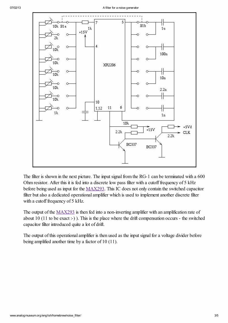
The filter is shown in the next picture. The input signal from the RG-1 can be terminated with a 600Ohm resistor. After this it is fed into a discrete low pass filter with a cutoff frequency of 5 kHzbefore being used as input for the MAX293. This IC does not only contain the switched capacitor
filter but also a dedicated operational amplifier which is used to implement another discrete filter
with a cutoff frequency of 5 kHz.
The output of the MAX293 is then fed into a non-inverting amplifier with an amplification rate of
about 10 (11 to be exact :-) ). This is the place where the drift compensation occurs - the switched
capacitor filter introduced quite a lot of drift.
The output of this operational amplifier is then used as the input signal for a voltage divider before
being amplified another time by a factor of 10 (11).

07/02/13 A filter for a noise generator
www.analogmuseum.org/english/homebrew/noise_filter/ 4/5
The picture on the right shows the front ofthe random noise filter. From left to right the
following elements can be seen:
LED showing that input signaltermination is in effect,
BNC input jack with termination
switch,eight position switch for selecting the
desired bandwidth,
output amplitude potentiometer and
the 4 mm banana jack delivering theoutput signal.

07/02/13 A filter for a noise generator
www.analogmuseum.org/english/homebrew/noise_filter/ 5/5
The picture on the left shows the output frequencyspectrum of the filter being fed with a 100 kHz
random noise signal from the RG-1. The filter has
been set to a cut off frequency of 1 Hz only (which
is what I need for my moving mass excitationcomputation) - it is incredible how sharp the cutoff
point in fact is (and it shows how good the RG-1 is
- even at very low frequencies is is a good white
noise signal) - the vertical hairline has been set at 1Hz.
[email protected] 21-JAN-2007