A E FA - Defense Technical Information CenterJA TECHNICAL REPORT ARLCB-TR-82007 "FRACTURE ANALYSIS...
46
S:JA TECHNICAL REPORT ARLCB-TR-82007 "FRACTURE ANALYSIS OF THICK-WALL CYLINDER PRESSURE VESSELS J. H. Underwood D. P. Kendall , . . April 1982 US ARMY ARMM T RESEARCH AND DEVELOPMENT COMM LARGE CALIBER WEAPON SYSTEMS LABORATORY BEN&T WEAPONS LABORATORY WATERVLIET, N. Y. 1.2189 AMCMS No. 61110191A0011 DA Project No. 1L161101A98A PRON No. 1A2231491AIA l 2- A'" 3 '~~ U,'.. J N , 15 10;•,2 A E FA APPROVED FOR PUBLIC RELEASE; r)ISTRIBUTION UNLIMITED m82
Transcript of A E FA - Defense Technical Information CenterJA TECHNICAL REPORT ARLCB-TR-82007 "FRACTURE ANALYSIS...

S:JA
TECHNICAL REPORT ARLCB-TR-82007
"FRACTURE ANALYSIS OF THICK-WALL
CYLINDER PRESSURE VESSELS
J. H. UnderwoodD. P. Kendall ,
. . April 1982
US ARMY ARMM T RESEARCH AND DEVELOPMENT COMMLARGE CALIBER WEAPON SYSTEMS LABORATORY
BEN&T WEAPONS LABORATORYWATERVLIET, N. Y. 1.2189
AMCMS No. 61110191A0011
DA Project No. 1L161101A98A
PRON No. 1A2231491AIA l 2- A'" 3'~~ U,'.. J N , 15 10;•,2
A E FAAPPROVED FOR PUBLIC RELEASE; r)ISTRIBUTION UNLIMITED
m82
SECURITY CLASSIFICATION OF THIS PAGE (When Data Entered)
r READ INSTRUCTIONSREPORT DOCUMENTATION PAGE RE COMPLETIORM[_______________________________________ BEFORE COMPLETING FORM
f1. REPORT NUMBER 2. GOVT ACCESSION NO. 3. RECIPIENT'S CATALOG NUMBER
ARLCB-TR-82007 .. 0-,//6 Yef _
4. TITLE (and Subtitle) 5. TYPE OF REPORT & PERIOD COVEREDFRACTURE ANALYSIS OF THICK-WALL CYLINDERPRESSURE VESSELS
"6. PERFORMING ORG. REPORT NUMBER
7. AUTHOR(e) S. CONTRACT OR GRANT NUIBER(a) 4
J. H. Underwood and D. P. Kendall
9. PERFORMING ORGANIZATION NAME AND ADDRESS 10. PROGRAM ELEMENT, PROJECT, TASK
US Army Armament Research & Development Command AFtEA & WORK UNIT NUMBERS
Benet Weapons Laboratory, DRDAR-LCB-TL AMCMS No. 61110191A0011
Watervliet, NY 12189 DrroN No. I21 6101APRON No. IA2231491AIA
1I. CONTROLLING OFFICE NAME AND ADDRESS 12. REPORT DATEUS Army Armament Research & Development Command April 1982Large Caliber Weapon Systems Laboratory 13. NUMBER OF PA.IES
Dover, NJ 07801 4014. MONITORING AGENCY NAME & AODRESS(If different from Controlling Office) "15 SECURITY CLASS. (of this report)
UNCLASSIFIED1Sa. DECLASSIFICATION/DOWNGRADING
SCHEDULE
IS. DISTRIBUTION STATEMENT (of Lthis Report)
Approved for public release; distribution unlimited.
17. DISTRIlBUTION STATEMENT (of the abitreat etered In block 20, if different from Report)
1o. SUPPLEME.NTARY NOTESSubmitted to: Case Studies in Engineering Mechanics and Materials
Presented to: ASTM E-24 Committee on Fracture, Philadelphia, PA,27-29 April 1982.19. KEY WORDS (Continue an reverse side it necesaryv and identify by block number)Fr. oture Analysis Residual StressPre.ssure Vessels Fracture MechanicsFatigue Life Crack Shape
240 A96TRACT fCsft = .e"twe, •- e rees --' ide hILr b* block ......)Fracture mechanics analysi•s of cylindrical pressure vessels is described in abrief fracture case study. Also included in this report are additionalexamples of crack growth in pressurc vessels and cannons.
The case study is of an early brittle failure and subsequent redesign of acannon tube. Fracture mechanics test methods are described which were
(CONT'D ON REVERSE)
,O IJAN 13 tUNCLASSIFIED
Sic-UmrTY CLASSIFICATION OF THIS PAGE (Wheg Date Entered)
SECURITY CLASSIFICATION OF THIS PAGE(Whan Data Bnt•
20. ABSTRACT (CONT'D)
"developed specifically for testing of Aind; Ic .eometries. Threeexamples of current fracture analysis L cylindrical pressure vessels arepresented. Fast fracture of a vessel is described, including effects oftension residual stress and crack shape. Evidence of environmentallyassisted fracture of a cannon tube is presented. Fatigue. crack growth andlife calculation methods for cylindrical pressure vessels are developed aid
¼.•' checked with experimental results; effects of compressive residual stressdue to overstrain are analyzed, including reductibno from the expecLed"theoretical residual stress due to reduced compressive strength of the alloysteel.
L" i
11
S&CURITY CLASSIFICATION OF THIS PAGE(,7ier. t).(. F-,r-d
TABLE OF CONTENTS
Page
ACKNOWLEDGEMENTS ili
INTRODUCTION I
AN EARLY FAILURE 1
Failure 1
p. Redesign 5
TEST METHOD DEVELOPMENT 8
EXAMPLES OF FRACTURE ANALYSIS 10
Fast Fracture 10
Environmental Fracture 13
Fatigue Fracture 15
REFERENCES 22
j; LIST OF ILLUSTRATIONS
1. Brittle Failure of 175 mm Cannon Tube. 25
2. Outline of Failure and Redesign of 175 mm Cannon Tube. 26
3. Contained Leak-Before-Break Cracking in a Cannon. 27
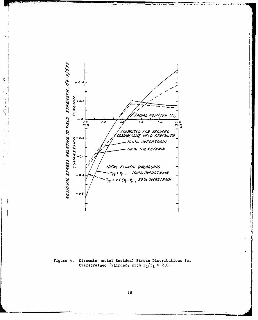
4. Circumferential Residual Stress Distributions for Over- 28strained Cylinders with r 2 /rl - 2.0.
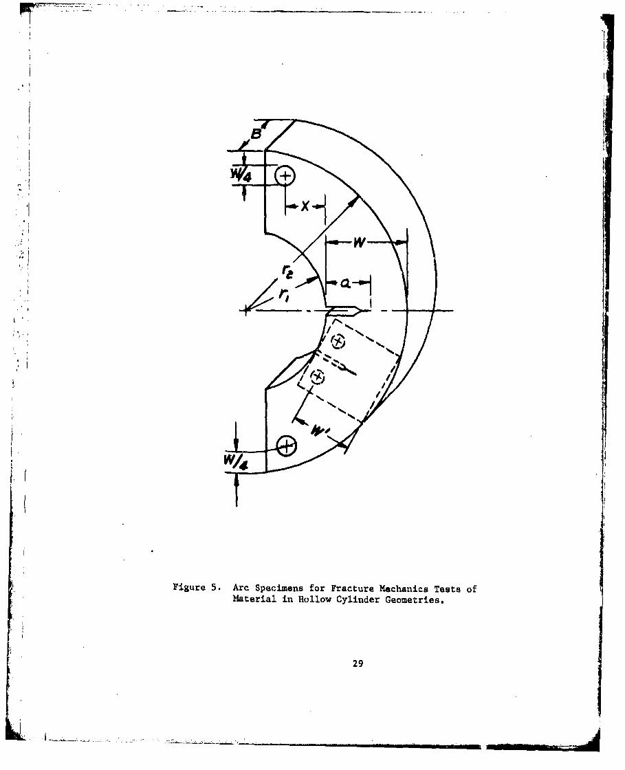
5. Arc Specimens for Fracture Mechanics Tests of Material in 29Hollow Cylinder Geometries.
6. Stress Intensity Factor, K, Results Eor Arc Specimen from 30Experiment and Analysis.
7. Variation of Fracture Toughness with Yield Strength for 31Ni-Cr-Ma-V Steel Forgings.
8. Fast Fracture Afrected by Crack Shape and Tensile Residual 32Stress.
L .. -<...,... .. . . .

' I
Page
9. Stress Corrosion Cracking in a Cannon Tube. 33
(a) Location 1 - Mixed Stress Corrosion and Fatigue Cracking;
Location 2 - Fast Fracture; Location 3 - Initiation ofStress Corrosion Cracking at Rifling Land; 15X.
(b) Micrograph of Location 3, 1OOX.
10. Scanning Electron Microscope Fractographs of Stress Corrosion 14A Initiated Cracking in a Cannon Tube.
(a) Stress Corrosion Cracking at Rifling Land, 400X.
I" (b) Fatigue Cracking at location I in Figure 9, IOOX.(c) Fast Fracture at Location 2 in Figure 9, 1700X.
1 1i. Sketch of Tensile Yielding and Reduced Compressive Yield 35
Strength for 100% Overstrained Steel Cylinder with r 2 /r 12.0.
12. Residual Stress and Stress Intensity Factor, K, Distributions 36
for 60% Overstrained Cylinder with ri - 2.0, p - 331 MPa,ai - 6.4 mm, a/2c - 0.5.Li
.0 13. Crack Depth Versus Number of Fatigue Cycles From Experiment 37and Analysis for Cylinders with 0% and 60% Overstrain,
r 90 nun, r2/ri - 2.0, p 331 MPa, ai - 6.4 mm, a/2c 0.5.
I
iii
iii
K i

ACKNOWLEDGEMENTS
We are pleased to credit Mr. B. B. Brown and co-workers for design and
execution of pressure vessel experiments, Mr. F. E. Mosc-inski and co-workers
for metallographic and fractographic analyses, and Mr. J. F. Throop and
co-workers for overstrain residual stress experiments.
:F ii
t.

INTRODUCTION
In basic function a ýannon is a pressure vessel, since it must contain
pressure in repeated application during its use. Thus, the engineering
analysis of fracture of cannons has application to pressure vessels in
general. Further, the geometry and materials used for cannons are often used
in other pressure vessel applications, such as high pressure piping and highJ
pressure containers for chemical processes. Because of such common features
between cannons and other pressure vessels, a description of fracture of
cannons should be of relatively general interest.
The objective of this report is to describe some key elements of the
fracture analysis of cannon pressure vessels performed by our laboratory, both
early and recent work. The discipline of linear elastic fracture mechanics
will predominate, because the failure of a cannon is usually a crack growth
process. The description is in three parts. First is an outline case study
of an early brittle failure of a cannon. This is foll.owed by a summary of
recent fracture-test-method development work and finally by examples of
fracture analysis, all of which are outgrowths of the early concern with
brittle fracture.
AN EARLY FAILURE fiueo rtclsrcua opnn sarmralFailure
An unexpected failure of a critical structural component is a remarkably
effective impetus to engineering analysis. The Army expcrienced a premature
field failure of a cannon tube during the 1960's, and this provided a dJignifi-
cant impetus to fracture analysis of cannon, particularly the pressurized corn-
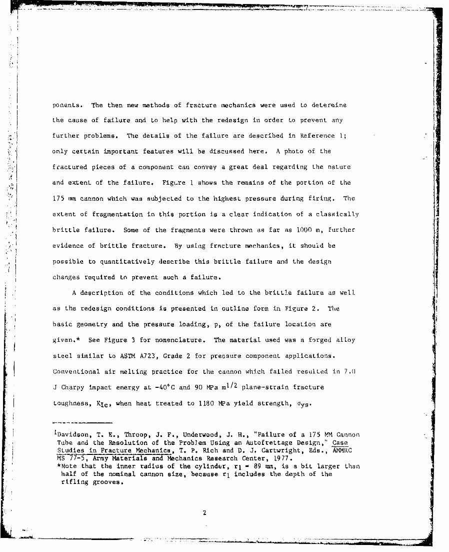
ponents. The then new methods of fracture mechanics were used to determine
the cause of failure and to help with the redesign in order to prevent any
¶ further problems. The details of the failure are described in Reference 1;
only certain important features will be discussed here. A photo of the
fractured pieces of a component can convey a great deal regarding the nature
and extent of the failure. Figure I shows the remains of the portion of the
175 mm cannon which was subjected to the highest pressure during firing. The
extent of fragmentation in this portion is a clear indication of a classically
brittle failure. Some of the fragments were thrown as far as 1000 m, further
evidence of brittle fracture. By using fracture mechanics, it should be
possible to quantitatively describe this brittle failure and the design
changes required to prevent such a failure.
A description of the conditions which led to the brittle failure as well
as the redesign conditions is presented in outline form in Figure 2. The
basic geometry and the pressure loading, p, of the failure location are
given.* See Figure 3 for nomenclature. The material used was a forged alloy
steel similar to ASTM A723, Grade 2 for preosure component applications.
Conventional air melting practice for the cannon which failed resulted in 7.0
J Charpy impact energy at -40*C and 90 MPa ml/2 plane-strain fracture
toughness, Klc, when heat treated to 1180 MPa yield strength, oys.
iDavidson, T. E., Throop, J. F., Underwood, J. H., "Failure of a 175 WM CannonTube and the Resolution of the Problem Using an Autofrettage Design," CaseStudies in Fracture Mechanics, T. P. Rich and D. J. Cartwright, Eds., AMMRCMS 77-5, Army Materials and Mechanics Research Center, 1977.*Note that the inner radius of the cylinder, rI - 89 mm, is a bit larger thanhalf of the nominal cannon size, because r1 includes the depth of therifling grooves.
2

The critical crack which initiated the failure was found in the area
which i6 subjected to both high pressure and the stress concentrations of the
rifling. The deepest fatigue crack in this area became the critical crack
with depth, ac, shape ac/2c, and relative depth, ac/W as indicated in Figure
•: 2. The critical crack had the C-R* orientation, shown in Figure 3. Fatigue
cracks were observed to initiate almost immediately in the cannon; the cowbi-
nation of transformational and thermal stresses at the inner radius during
firing could lead to a network of heat-check cracks as deep as I mm in about
ten firing cycles. Growth from such an initial, heat-check crack to the final
depth of 6.4 mm occurred in 600 firing cycles, with most cycles at an internal
pressure of 345 iWa. Overlooking for the purposes here the specific processes
by which the crack grew, the dominant fact is that brittle fracture occurred
with a crack depth of only one tenth of the wall thickness. If it can be
shown that the stress intensity factor, K, which was applied to the cannon at
failure is close to the measured plane-strain fracture toughness, Kic, this
would explain the failure and initiaLe a proper approach. for redesign.
An expression for K of an internally pressurized cylinder with a C-R
orientation surface crack at the inner radius can be written based on a
combination of the work of Bowie and Freese 2 and Newman and Raju: 3If fs p(ira)1/2 (1)
2 Bowie, 0. L. and Freese, C. E., "Elastic Analysis For a Radial Crack in aCircular Ring," Engineering Fracture Mechanics, Vol. 4, 1972, pp. 315-321.
3 Newman, J. C., Jr., and Raju, I. S., "An Empirical Stress-Intensity FactorEquation for the Surface Crack," Engineering Fracture Mechanics, Vol. 15,1981, pp. 185-192.
*Plane normal to the circumferential direction, growth in the radialdirection, see ASTM Method E399.
3
- -4---•_-.- S -[

In Equation (1) fp is a dimensionless factor which accounts for the specific
radius ratio, r 2 /r 1 and relative crack depth, a/W of the cylinder under
K consideration; it can be obtained from the collocation r•Jsults of Reference 2.
The factor fs accounts for the crack shape, a/2c and a/W, and is obtained
following some calculations from the equations of Reference 3 which are based
on finite element results from plates under tensior. and bending loads. IL is
often necessary to use a weighted shape factor, fs, which accounts for the
relative proportions of tension and bending load in a cylinder. For the a/2c
and a/W at failure of the cannon here, this is not necessary because fS for
both tension and bending is close to 0.70. This means that K at the point of
deepest penetration of the surface crack is 0.70 times that of a straight.-
fronted crack of the same depth in the cylinder. Using this value and fp
2.70 from Reference 2, gives an applied K at failure of 112 KPa m1/2, which is
1.24 times the value of KI. An applied K required for fracture which is
somewhat above KIc would be expected because of the loss of plane-strain
constraint at the crack tip caused by the small crack depth.* Therefore the
brittle failure of the cannon is satisfactorily explained, and linear elast.ic
fracture mechanics seems appropriate for use in the redesign process.
24owie, 0. L. and Freese, C. E., "Elastic Analysis For a Radial Crack in aCircular Ring," Engineering Fracture Mechanics, Vol. 4, 1972, pp. 315-321.
3 Newman, J. C., Jr., and Raju, I. S., "An Empirical Stress-Intensity Factor
Equation for the Surface Crack," E nineering Fracture Mechanics, Vol. 15,• i 1981, pp. 185-192.
*When the crack tip is near a free surface, whether due to a shallow cracknear the "front" surface or a deep crack near the "back" surface, there is aloss of plane-strain constraint.
4Lt

•ii Redes ign
ii
The objective of the cannon redesign was the same as that often applied
to critical pressure vessel components, a leak-before-break criteria for any
crack-related failure. When a leak-before-break can be assured, a contained
failure of the vessel occurs of the type shown in Figure 3 for a cannon. 4
In this case severe heat-checking of the inner radius (bottom of photo)
quickly initiated a crack which grew by fatigue to a point about nine tenths
through the wall thickness (light band near top of photo). The final fast
failure through to the outer radius occurred as a relatively short, through
crack which showed no tendency to run down the axis of the cylinder.
Three basic changes were made with the 175 mm cannon in order to increase
the material fracture toughness relative to the applied K and therefore
achieve a leak-before-break condition: (1) The specified yield strength was
decreased from a nominal 1180 to 1030 MPa. (2) Vacuum melting practice was
incorporated for the steel, as is now required in ASTM A723 steel. (3) Com-
pressive residual stresses were produced near the inner radius of the cannon
by an overstraining process. The important effect of the first two changes
was a significant increase in the average -40*C Charpy impact energy and the
fracture toughness, see Figure 2. The primary intended effects of the over-
strain residual stress were to compensate for the decrease in yield streiigth*
4 Underwood, J. H. and Throop, J. F., "Surface Crack K-Estimates and FatigueLife Calculations in Cannon Tubas," Part-Through Crack Fatigue LifePrediction, ASTM STP 587, J. B. Chang, Ed., American Society for Testing andMaterials, 1979, pp. 195-210. ap
• • *The compressive residual stress at the inner radius, where the appliedtensile stresses are maximum, more than compensates for the drop in tensile
!. ' yield strength.
5
.-

r',I
and to decrease the rate of growth of fatigue cracks (discussed in an upco-inng
section). In addition, the residual stress can be seen to have a beneficial
effect on brittle fracture.
Expressions are available for the r'-tdual stresses in an overstrailned
cylinder. For the plastically overstrained portion of a cylinder, rl < r '.
,rys,and using the Tresca yield condition, the circumferential residual
stress is 5
0 0-R r12 r 2
2 ry r rys rys 2 +r2 2 ry2-rj)(i + ln +-- +-- ------ ln-A
G r-r2 r 2 rI 2r2 2 r ("
For the elastic portion of a partially overstrained cylinder, rys < r < r2,2 2r2s2 r2I
c- O -R r22 rys2 r12 rys _2ry 2(! ... . [ + ; _ ][; • +s n rys
r 2 r 22 _r 2r22 ln-- ] ())
[ys - - rl
FTigure 4 shows plots of Equations (2) and (3) for a cylinder with r 2 /rl 2.0
for 50% and 100% overstrain conditions, that is, for ideal overpressures of a
cylinder where plastic deformation proceeds half and full way through the wa~l.
thickness. Also shown in Figure 4 are modified residual stress disLributions
which are corrected for the reduction in compressive yield strength which
occurs in the steel considered here following tensile yielding. For example,,
following the approximately 1% tensile plastic strain at the inner radius
which occurs during 100% overstrain of an r 2 /rl = 2.0 cylinder, the compres-
sive yield strength is only 0.53 times the unaffected value, 6 so the residual
5 Davidson, T. E., Kendall, D. P. and Reiner, A. N., "Residual Stresses inThick-Walled Cylinders Resulting From Mechanically Induced Overstrain,"Experimental Mechanics, Vol. 3, 1963, pp. 253-262.
6Milligan, R. V., Koo, W. H., and Davidson, T. E., "The Bauschinger Effect ina High-Strength Steel," Journal of Basic Engineering, Transactions ASME, Vol.88, 1966, pp. 480-488.
6

streels relative to yield strength is reduced from the ideal value of 0.85 to
0.53. Such effects of compressive strength reduction on rasidual stress and
thus indirectly on fatigue crack growth rate aud fatigue life, are described
further in an upcoming section.
The effect of residual stress, including the appropriate compressive
strength reduction, on brittle failure of the redesigned cannon can be
determined as follows. From Figure 4, for 50% overstrain which was used in
redesign and for the relatively shallow crack depth of the prior failure,
r/rI - 1.10, the residual stress is 0.38 times the yield strength, 0 0-R - -390
RPa This value* can be used in a modifi.cation of Equation (1) to obtain an
approximate K expression which includes the effect of residual strees,
K- fpfs P(¶a)1/2 + 1.12 fs 06-R(la)I/2 (4)
Using a0 _R - -390 MPa and with all other values as before, the applied K with
residual stress pcesent is significantly reduced, see Figure 2. This,
combined with an increased KIc, makes failure at such small crack depth (a
O.iW) quite unlikely. Failure at a deep crack is still possible, but for a
deep crack for which the benefita of residual stress diminish, the loss of
plane-Ptrain constraint as the crack approaches the outer radius causes an
increase in effective fracture toughness, This will tend to compensate for
the loss of benefit from residual stress. Of coarse, the proof of Lhe
redesign is in the experienue. Since the redesign of the 175 mm cannon to the
material property and residual stress conditions indicated in Figure 2, there
*This value is correct for a cylinder with r2/rI - 2.00, whereas the cannonbeing considered has r 2 /rl - 2.09. The difference between the two resultswill have no effect on conclusions drawn from the analysis.
7
have been no further brittle failures, even after many times the number of
firing cycles of the early failure.
TEST METHOD DEVELOPMENT
The importance of fracture toughness testing to the structural integrity
of high strength pressure vessels is apparent from the preceding discussion.
When brittle fracture is possible, fracture toughness testing is essential.
In reaction to this, a new fracture specimen has been developed which is
," ! uniquely suited to cylindrical pressure vessels. 7 First called the C-shaped
specimen, more recently the arc specimen, it is now used worldwide and is part
of ASTM Method E-399 for Plane-Strain Fracture Toughness of Metallic
Materials.8
The arc specimen is shown in Figure 5 along with the dashed outline of
the rectangularly shaped compact specimen. By using the full wall thickness
of a cylinder, the arc specimen both saves fabrication time and yields a
larger effective sperimen depth, W, than does a rectangular specimen taken
from the same cylinder.
The development, of the arc specimen included boundary value collocation
and experimental cow-)liance stress intensity factor, K, analyses of
prospective goometries by three different laboratorils. 9 A sample of results
7 kendall, D. P. and Hussain, M. A., "A New Fracture Toughness, Test Method forThick-Walled Cylindo,-:' Material," Experimental Mechanics, Vol. 12, 1972, pp.184-189.
8 "Standard Test Method For Plane-Strain Fracture Toughness of Me.allicNaterials," E-399, Antual Book of ASTM Standards, Part 10, American Societyfor Testing and Matierial, 1981, pp. 588-618.
9 Underwood, J. H. and Kendall, D. P., "Fracture Toughness Testing Using theC-Shaped Specimen," Pvj.eLopmenti in Fracture Mechanics Test MethodsStandardizatioii, ASTM OTP 632. W. F. Brown, Jr. and J. G. Kaufman, Eds.,/u.erican Society fur Testing and Materials, 1977, pp. 25-38.
8

from these analyses is shown in Figure 6. In general, and as shown in Figure
6, the agreement between the collocation results from two different labora-
tories and methods was excellent, within a few tenths of'a percent. The good
agreement, within a few percent, between the experimental compliance K values
7 and those from collocation is a further independent check on the stress and K
analyses of the arc specimen.
Polynomial expressions have been developed to rtpresent the collocation
results while still converging to the exact limit solution for shallow and
deep cracks. A recent extension of an earlier expression is accurate within
t three percent over a wide range of geometry* for arc specimens and is part
of ASTM Method E399. It isI 0
(B (1 1/2KW3X a a rl W
" [ -+ 1.9 + 1. ]1 + 0.25(l -)2( 1 - --)][ -- --- -
a r, Xfor 0.2 < - 1 1, 0 • -- 4 1.0, 0 < - ( 1.0.
W r2 W
The key to a wide range K expression, as discussed by Srawley, 1 1 is
attention to deep crack limit solutions. For the arc specimen the imporLant
solution is bending of the uncracked ligament ahead of a deep crack approach-
10 Kapp, J. A., Newman, J. C., Jr., and Underwood, J. H., "A Wide Range StressIntensity Factor Expression For the C-Shaped Specimen," Journal of Testingand Evaluation, Vol. 8, 1980, pp. 314-317.
11Srawley, J. E., "Wide Range Stress Intensity Factor Expressions for ASTME-399 Standard Fracture Toughness Specimens," International Journal ofFracture Mechanics, Vol. 12, 1976, pp. 475-476.
*For the specific geometries of KIc testing, the expression is accurate within
± one percent.
9
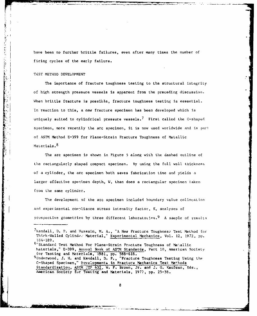
ing a free surface, in this case the outer radius. in the terminology
here, the deep crack limit K is:
3.975[- + - + a_
*KBWIn 2 W 2 2W
P a
(I - -)3/2W
where the bracketed term is the bending moment arm for the arc specimen.
The form and constants of Equation (6) and a similar tension limit
solution were used in developing the wide range K expr . ton for the arc
specimen. Because K converges to the proper deep crack ..mit, the specimen
can be used for fatigue crack growth tests and other fracture mechanics tesLs
whiLh involve deep cracks. The arc specimen can also be used for J-integral
tests to measure JIc and for tests involving bending loads, although specific
procedures for these tests have not been well documented yet.
EXAMPLES OF FRACTURE ANALYSIS
Fracture of pressure vessels can be categorized using three basic types
of crack growth: fast crack growth, environmentally assisted crack growth,
and fatigue crack growth. A recent example of each type of crack growth in 4cannons is given here to illustrate current applications if £Ldcture mechanic.-;
to cylindrical pressure vessels.
Fast Fracture
The beneficial effect of lowering the yield strength in preventing fast,
brittle fracture was included in the discussion of the early failure. The
strength level effect is so basic to fracture concerns with pressure vessels
10
-!

that it should be considered further. Figure 7 shows test results from eight
different types of forged cylindrical pressure vessels, 12 some for prototype
cannons, some for research purposes. The material is the ASTM A723 steel
discussed earlier, with vacuum processing used in all cases. The vacuum
processing and the prototype nature of the forgings combine to give fracture
toughness values which are near the upper limit for this class of material.
"Nevertheless, the results show clearly the typical decrease in toughness which
L.:I' is obtained with an increase in yield strength. This is a consistent tcend for
the ASTH Kic measurement,:, for KIc measurements with a smaller than required
specimen size, and for KI, calculated from the result of J-integral, Jlc tests.
The linear regression line and ± 10 percent limits show that, only for the
material and strength range here, there is an inverse linear relation between
toughnese and strength with relatively little scatter. The variation of -40*C
notched impact charpy energy with room temperature yield strength is also shown
in Figure 7 for six of the eight types of forgings. Again, an inverse relation
exists between charpy energy as a measure of toughness and yield strength.
Note that it is not a linear inverse relation, so linear correlations between
v charpy Piergy and KIc should not be attempted.
The likelihood of fast cracking is certainly affected by factors other
than the material fracture toughness. A recent experience with a pressure
vessel demonstrates the effects of crack shape and tensile residual stress on
12 Underwood, J. H., "The Equivalence of KIc and JIc Fracture ToughnessMeasurements in Ni-Cr-Mo Steels," Experimental Mechanics, Vol. 18, LY78, pp.350-355.
111

fast sracking. A 1.5 m long, overstrained cylinder with ri = 79 mm and r 2 =
142 mm was cyclically pressurized with oil from 0 to 386 MPa. A fatigue crack
initiated at a 10 mm deep, 25 mm wide, 550 mm long longitudinal notch on the
outer diameter. The fatigue crack grew to the critical size at which Kjc
controlled fast cracking occurred. The resulting failure did not involve
fragmentation, so it was not a brittle failure in that sense, but neither was
it a leak-before-break failure. Figure 8 shows a portion of the fracture
surface, as well as the distribution of overstrain residual stress present in
Lhe cyli,-.ýzr before fracture. The maximum depth of the notch plus the
critical fatigue crack was 16 mm, only about one quarter of the cylinder wall
thickness when fast fracture of the remaining wall thickness and the entire
cylinder length occurred.
Fast fracture from such a shallow crack was affected by (1) the tensile
residual stress in the outer portion of the cylinder due to the 100%
overstrain, and (2' the long, straight-fronted crack shape due to the notch.
A measure of the effect on the applied K of these two factors can be obtained
from an expression for K for an O crack in the cylinder. The expression is
obtained using an approach similar to that for Fquation (4):
K - 1.12 fs (O0-R + UO-p)(Tra)1/2 (7)
The shape factor, f., has a value very near 1.0, because the crack is
essentially straight-fronted. So the reduction in K associated with the more
usual semielliptical shaped crack is not present in this case due to the
I ngitudinal notch. The tensile residual stress at the location of the
critical crack, 06-R, can be estimated from Figure 4 as about 0.22 times the
yield strength, 1230 MPa. This estimate, 270 MP&, takes into account the
12
| .
reduced compressive yield strength discussed earlier and the fact that r2/rl -
1.8 for this cylinder. The tensile applied atress in the cylindez can be
calculated from the well known relation for a cylinder: 1. 3
p[l + (r2/r)210 G-P - -- ---- ---- (8)
(r2/rl) 2 - 1
In the above r 2 /r - 1.13 for a crack one quarter through the wall, and a0 p -
391 MPa.
"Applying the above values of fs, G0-R and ao.p to Equation (7), along
with a - 16 mm - 0.016 m, gives an applied K - 166 MPa-mu/2. This is somewhat
above the Kjc value from the cylinder material, 162 WPa'ml/2, so the fast
failure would not be unexpected. The important point is that both the crack
shape and re,'idual stresses had significant contributions to the fas•
fracture. These factors must be reckoned with in the fracture analysis of
pressure vessels.
Environmental Fracture
Environmentally assisted fracture is an important consideration in
pressure vessels because three basic requirements for this type of fracture
are often present, susceptible material, sustained texisile loading, and
aggressive environment. Pressure vessels are often made of high strength
materials, many of which are susceptible to environmentally assisted fracLure.
which may be aggressive are contained.
13Timoshenko, S. and MacCullough, G. H., Elements of Strength of Materials,D. Van Nostrand Co., Princeton, NJ, 1949, p. 26.
13

-- i-
The above tiree requirements were present and led to a recent example of
stress corrosion cracking in a cannon tube. The high strergth steel alloy is
susceptible to stress corrosion cracking in certain environments. The 8ub-
tained tensile loading present in this case is believed to be tensile residual
stress which was caused by compressive yielding resultitig from the combination
of thermal and overstrain stresses at the inner radiua of the tube. The
environment was the firing products which include hydrogen sulfide, a highlyaggressive environment for stress corrosion c.acking in many steels.
The stress corrosion cracking of the cannon tube is described by two pho-
' tomicrographs. Figure 9a is a cross-section of a piece of a tube in which
cracking has occurred. The section is lightly shaded due to the Metallo-
graphic polish. It contains two rifling lands at the iiner radius. The pri-
mary crack started at the corner of a rifling land, grew by mixed stress cot-
rosion and fatigue cracking (location 1), and then grew in the radial direc-
tion by mixed fatigue and fast cracking (location 2) out toward the outer
radius and a leak-before-break failure. A smaller crack at a rifling land
(location 3) is shown at higher magnification in Figure 9b. The classic,
multiply-branched cracking is a clear indication of stress corrosion cracklfi,.
Figure 10 shows scanning electron microscope fractographs which compare the
stress corrosion, fatigue, and fast fracture regions and further confirm thit
the initiation and primary cause of the failure was environmentally assisted
fracture.
This environmentally controlled failure in a gun tube occurred after
several years of service, and the final failure was safe and contained. The
delay in environmentally assisted failure nearly always occurs; the safe final
condition does not. Whenever the combination of sustained loading and an
14

unsuitable material/environment couple is present in a pressure ve'sel,
environmentally assisted failure must be considered.
Fatigue Fracture
Repeated application of pressure to vessels provides the means whereby
cracks, which initiate due to stress concentrations or service environments,
can grow to the critical size required for fast fracture. This is a common
sequence of events for cannon pressure vessels. Often the fatigue crack
growth process is most of the life of a cannon, so considerable fatigue life
testing and associated analysis of cannons has been performed. References 14,
15, and 16 are examples. Much of the life testing and analysis has centeredon the two factors already discussed here, crack shape and residual stress.
With the recent comprehensive wrk of Newman and Raju, 3 the effects of crack
shape on K and thus on cracking and fatigue life can be well characterized.
Also, many investigators are now addressing the second factor, the effects of
residual stress on life. In demonstration of this, a new ASTM subcommittee
has recently been formed, E9.02, Residual Stress Effects in Fatigue.
3Newman, J. C., Jr., and Raju, I. S., "An Empirical Stress-intensity FactorEquation for the Surface Crack," Engineering Fracture Mechanics, Vol. 15,1981, pp. 185-192.
14Davidson, T. E., Brown, B. B., and Kendall, D. P., "Materials and ProcessesConsiderations in the Design of Pressure Vessels," High PressureEngineering, H.L.I.D. Pugh, Ed., The Institution of Mechanical Engineers,1977, p 63-71.
15Davidson, T. E. and Throop, J. F., "Practical Fracture MechanicsApplications to Design of High Pressure Vessels," Application of FractureMechanics to Design, J. J, Burke and V. Weiss, Eds., Plenum PublishingCorp., New York, 19711, pp. 111-138.
16Parker, A. P., Underwood, J. H., Throop, J. F., and Andrasic, C. P., "StressIntensity and Fatigue Crack Growth in a Pressurized Autofrettaged ThickCylinder," submitted to Proceedings of 14th National Symposium on FractureMechanics, Los Angeles, June 1981. 1
' .. .... ... . . .. , , - 11 5

The work of Parker et a11 6 specifically addresses the effects of residual
stress on the life of cannon pressure vessels. They developed K expressions
for pressurized cylinders with overstrain residual stress, and they numeri-
cally integrated da/dN versus AK expressions to calculate life as affected by
residual stress. Comparison of calculated with actual lives led them to con-
clude that accurate determination of the residual stress actually present in a
cylinder is required for reliable life calculations. A reexamination of Fig-
ure 4 will support this conclusion. In all the plots shown, the compressive
stress is significant relative to yield strength near the inner radius, where
much of the fatigue life is expended. Thub, the correctness of this residual
stress will have a large effect on the calculated life, and a small change in
this stress can have a much magnified effect on the actual life, because there
K1 is a near balance between applied tension arrd residual compression stress. In
the following last example of fracture mechanics analysis of cylindrical
pressure vessels, an estimate of the actual residual stress distribution in an
overstrained cylinder and its effect on fatigue life will be described.
Comparison will be made between calculated fatigue life and laboratory
measurements1 6 from full size cylinders.
First, an estimate of the actual residual stress distribution in an
overstrained cylinder is made, as opposed to an analysis which assumes ideal
elastic unloading of a cylinder during overstrain. Milligan6 showed that A723
6 Milligan, R. V., Koo, W. H., and Davidson, T. E., "The Bauschinger Effect ina High-Strength Steel," Journal of Basic Enineern_, Transactions ASME,
Vol. 88, 1966, pp. 480-488.16Parker, A. P., Underwood, J. H., Throop, J. F., and Andrasic, C. P., "Stress
Intensity and Fatigue Crack Growth in a Pressurized Autofrettaged ThickCylinder," submitted to Proceedings of 14th National Symposium on Fracture
Mechanics, Los Angeles, June 1981.
16
type 3teels, following tensile plastic deformation, exhibit a reduction in
compressive strength properties, called the Bauschinger effect. For the situ-
ation here, the overstrain of a cylinder, Figure 11 summarizes this effect.
The plot is an estimate of the effective stress versus strain history at the
inner radius of an r2/rl - 2.0 cylinder as it undergoes a 100% overstrain pro-
cedure. Davidson et a117 calculated the tensile plastic deformation for these
conditions to be 1.01%. For this amount of tensile plastic deformation, the
reduced compressive yield properties 6 are compared with linear unloading in
Figure 11. Using the reduced properties, corrected values of overstrainresidual stress in a cylinder can be obtained. For example, from Figure 11
the value of circumferential residual stress at the inner radius, .O._R, for
ideal linear unloading is 0.85 times the unaffected yield strength, or 1000
MPa in this case. When the reduced compressive yield properties are used, the
corrected value is 620 MPa. Applying such corrected values of compressive
yield strength to several points in the compressive residual stress region of
the overstrained cylinder gives the corrected residual stress distribution
plots shown in Figure 4. The tensile portion of the corrected plots in Figure
4 was obtained by reducing the total area above zero stress in the tension
portion by the same ratio as that obtained in the compression portion.
A proof of a corrected residual stress distribution is to use it to
calculate fatigue life for comparison with experiment. This was done and is
6Milligan, R. V., Koo, W. H., and Davidson, T. E., "The Bauschinger Effect ina High-Strength Steel," Journal of Basic Engineering, Transactions ASRE,Vol. 88, 1966, pp. 480-488.
17 Davidson, T. E., Barton, C. S., Reiner, A. N., and Kendall, D. P.,"Overstrain of High-Strength Open-End Cylinders of Intermediate DiameterRatio," Proceedings of the First International Congress on ExperimentalMechanics, Pergamon Press, Oxford, 1963, pp. 335-352.
17
Is - .aihýiMihil-1 1-"
summarized in Figures 12 and 13. Fatigue life calculations were wade for the
conditions of recent fatigue life experiments,1 6 0% and 60% overstrained
cylinders with r2/r1 - 2.0, rl - 90 mm, yield strength -. 1175 MPa, internal
L pressure p - 331 MPa, and a semicircular starter notch with initial depth ai
[•• !6.4 mam. Figuie 12 shows the residual 9txess distribution calculated from
Equations (2) and (3) which assume ideal elastic unloading. Also shown is the
distribution corrected for reduced compressive strength, using the method
described in relation to Figures 4 and 11. The compressive residual stress at
the inner radius, 'o-R for r - rl, is decrea, from -860 MPa to -600 MPa
by the correction.
The ideal and corrected stress distributions shown in the lower plot of
Figure 12 are used to obtain K distributions for a pressturized, overstrained
"tube using the following general expression 4
K/oo(Tra)1/2 - 1.12 - 0.68(a/ao) (9)
Equation (9) is a short crack K expression for a linear varying stress
distribution in which 0o is the stress for a - 0, that is, at the edge of the
specimen, and ao is the crack length for a - 0, that is, for the point where
the stress distribution crosses the zero stress line. Equation (9) can be
applied to the nearly linear stress distributions in Figure 12 by letting uo I0.0-R (for r - rI) and ao - 0.38 W, that is, r/rl - 1.38. Doing so and
4 Underwood, J. H. and Throop, J. F., "Surface Crack K-Estimates and FatigueLife Calculations in Cannon Tubes," Part-Through Crack Fatigue LifePrediction, ASTM STP 587, J. B. Chang, Ed., American Society for Testing andMaterials, 1979, pp. 195-210.
16Parker, A. P., Underwood, J. H., Throop, J. F., and Andrasic, C. P., "Stress
Intensity and Fatigue Crack Growth in a Pressurized Autofrettaged ThickCylinder," submitted to Proceedings of 14th National Symposium on FractureMechanics, Los Angeles, June 1981.
18

combining the resulting K distribution for compressive itiess with that l:ronl
the applied tensile loading due to pressure 2 gives the total K distLibutio,,
shown in the upper plot of Figure 12. Note that the total K, based on ideal
elastic unloading, nearly vanishes for r = rl, whereas the total K correcLtl,,,
for reduced compressive stress is significantly higher. This has a siglf--i,'•,;
effect on fatigue life.
Fatigue life can be calculated from a known K distribution by integratie,,
of a Paris-Erdogan 1 8 type equation:
da/dN C AK3 (I K
where C is a material constant from fatigue growth rate tests, and the p•)1jci
is often a good representation for steels. For applications in which the
minimum load is either compression or zero, as is the case here, AK is
equivalent to the maximum K. If it can be asswned that the simple K parim( ,
fk- K/p(jTa)1/2, remains constant, the integration of Equation (10) is siinpl,.
Referring again to Figure 12, fk is near).- constant for K due to pressure o,] y,
but is less so for total K. Nevertheless, a constant value of fk will be tv,,,
here with the rationale that the select,'or of a representative, average fk wi I I
provide a consistent, readily understandabli method for calculating fatgtiu,
life. Taking this approach, the integration of Equation (10) gives
2(ai- 1 / 2 - af-1/2)
N = (I-)C(fkfs p-gI/2) 3
2 Bowie, 0. L. and Freese, C. E., "Elastic Analysis For a Radial Crack in aCircular Ring," Engineering Fracture Mechanics, Vol. 4, 1972, pp. 315-321.
18Paris, P. C. and Erdogan, F., "A Critical Analysis of Crack PropagationLaws," Journal of Basic Engineering, Transactions ASME, Vol. 85, 1963, pp.528-534.
19
[ ! iS. . . .. . . . ..-
where N is the number of pressure cycles required to grow a crack from an
initial to a final crack depth, ai to af. Calculations of N were made using
the following values in Equation (11): ai = 0.0064 m; af - 0.090 mn, the full
wall thickness; C = 6.52 x I012 cycle-' MPa 3 m-1/2, the value from growth
rate tests; p - 33] MPa; fk = 2.76 for 0% overstrain, 1.37 for 60% corrected,
1.00 for 60% ideal; fs - 0.53. The values of fk wer• taken from Figure 12 for
r/r 1 1.2, which was selected by engineering judgment as the crack depth, a/W
= 0.2, which gives a representative value of K for describing fatigue life.
The value of fs was taken from Reference 3 for this crack depth, a/W = 0.2,
and the semicircular shape, a/2c - 0.5.
The comparison of calculated with experimental a versus N curves is shown
in Figure 13. The experimental curves are based on crack depth measurements•
using an ultrasonic method and on markings observed on the fracture surface
after the tests. The crack shape remained nearly semicircular throughout both
tests. The calculated curves for 0% overstrain and 6C% overstrain with ideaL
elastic unloading result in about the same comparison with experiment as jobserved in the numerical calculations of Parker et al, 1 6 that i,, the (M.
calculation is less than half of the experimental life and the 60% ideal.
calculation is more than twice the experimental life, The calculated curve
for 50% overstrain with correction fo. reduced compressive stLrength agrees
3 Newmnan, J. C., Jr., and Raju, I. S., "An Empirical Stress-lntensity Factor
Equation for the Surface Crack," Engineering Fracture Mechanics, Vol. 15,1981, pp. 185-192.
16Parker, A. P., Underwood, J. H., Throop, J. F., and Andrasic, C. P., "StressIntensity and Fatigue Crack Growth in a Pressurized Autofrettaged ThickCylinder, submitted to Proceedings of 14th National Symposium on Fracturemechanics, Los Angeles, June 1981.
20
, A7

-I M oil
much better with experiment and, in addition, is more consistent because It.
underpredicts the experimental life as does the 0% calculation. In summary,
I the proposed correction accounts for the known redu,-tion in compressive
strength of the material, and it also gives better and more consisLenL
agreement between calculated and experimental fatigue life.
A
"21
21

REFERENCES
1. Davidson, T. E., Throop, J. F. and Underwood, J. H. "Failure of a 17') 'I
Cannon Tube and the Resolution of the Problem Uhsing an Aitofrvt.Ltam'.,
Design," Case Studies in Fracture Mechanics, T. P. Pic.h and 1). .1.
Cartwright, Eds., AMMRC MS 77-5, Army Materials and M-echaniv s R•,•;';,r h
Center, 1977.
2. Bowie, 0. L., and Freese, C. E., "Elastic Analysis For a lkidtal Cr,ýOI 1i-
Circular Ring," Engineering FractureMechanics, Vol. 4, 1q72, pp. 31l'i-11.
3. Newman, J. C. Jr., and Raju, I. S., "An Empirical Stress-Intensity Ic! .1
Equation for the Surface Crack," Enginaeri ngFracture Mechanics, Vol.
1981, pp. 185-192.
4. Underwood, J. H. and Throop, J. F., "Surface Crack K-Est•.mates and 1'at.,,'
Life Calculations in Cannon Tubes," Part-Through Crack Fat.I.eFhLcfe
Prediction, a STM STP 587, J. B. Chang, Ed., American Society for Tcst H",
and ;Aaterials, 1979, pp. 195-210.
5. Davidson, T. E., Kendall, D. P., and Reiner, A. N., "Residual St rosso,; ,
Thick-Walled Q;ylinders Resulting From Mechanically Induced Overstratl),'
Exp;rimental Mechanicq, Vol. 3, 1963, pp. 253-262.
6. Milligan, R. V., Koo, W. 1H., and Davidson, 1'. E., "The l~auschingel IIe, f
in a High-Strength Steel," Journal of Basic Engineern~l, Transact ons
ASME, Vol. 88, 1966, pp. 480-488.
7. Kendall, D. P. and Hussain, M. A., "A New FracLure Toughness Test Method
for Thick-Walled Cylinder Material," Experimental Mechanics, Vol.. P,
1972, pp. 184-189.
22

8. "Standard TesL Method For Plane-Strain Fracture Touglness of Metallic
Materials," E-399, Annual Book of ASTM Standards, Part 10, American
Society For Testing and Materials, 1981, pp. 588-618.
9. Underwood, J. H. and Kendall, D. P., "Fracture Toughness Testing Using
the C-Shaped Specimen," Developments in Fracture Mechanics Test Method.,
Standardization, ASTM. STP 632, W. F. Brown, Jr. and J. G, Kaufman, Eds.,
American Society for Testing and MaLerials, 1977, pp. 25-38.
10. Kapp, I. A., Newman, J. C. Jr., and Underwiood, J. H., "A Wide Range
SLvess intensity Factor Expression For the C-Shaped Specimen," Journal '21
Testing arid Evaluat.ion, Vol. 8, 1980, pp. 314-317.
11. Srawley, J. 1e., "Wide Range Stress Intensity Factor Expressions for ASTM
E-399 Standard Fracture Toughness Specimens," International Journal of
Fracture Mechanics, Vol. 12, 1976, pp. 475-476.
12. Underwc d, J. H., "The Equivalence of Kjc and Jjc Fracture Toughness
M~easueiiWLu in NI -Ca-fo Steels " Experimental Mechanics, Vol. 18, 1978
pp. 350*-355.
13. Tfinislinl•o, 1;., :iild ?licCullough, C. II., Elements of Stren th of
Materlas, 1). Val NostLand Co., Princeton, NJ, 1949, p. 26.
14. 1)av .doii, 'r. i. , Urowa, 1 B . , ;inh1 Kendall, D. P., "Materials and
P1t:kcsm(iU ('i1i1.dC alt oki in thi he Oeilgn of Pressure Vessels," High
Prssurelsig:er-ingi, U{.L.1.D. Pugh, Ed., The Institution of Mechanical
Engineers, 19/7, pp. 63-71.
23
L 1 .

F
15. Davidson, T. E. and Throop, J. F., "Practical Fracture Mechanics
Applications to Design of High Pressure Vessels," Application of Fracture
Mechanics to Design, J. J. Burke and V. Weiss, Eds., Plenum Publishing
Corp., New York, 1979, pp. 111-138.
16. Parker, A. P., Underwood, J. H., Throop, J. F., and Andrasic, C. P.,
"Stress Intensity and Fatigue Crack Growth in a Pressurized AutofretLagod
Thick Cylinder," submitted to proceedings of 14th National Symposium on
Fracture Mechanics, Los Angeles, June 1981.
17. Davidson, T. E., Barton, C. S., Reiner, A. N., and Kendall, 1). P.,
"Overstrain of High-Strength Open-End Cylinders of Intermediate Diameter
Ratio," Proceedings of the First International Congress on Experiietital
Mechanics, Pergamon Press, Oxford, 1963, pp. 335-352.
18. Paris, P. C., and Erdogan, F., "A Critical Analysis of Crack Propagat•inLaws," Jornal Transactions ASME, Vol. 85, 1963,
pp. 528-534.
24

iI
iii
h-%%
Figure 1. Brittle Failure of 175 mm Cannon Tube.
25

FIGURE 2
FAILURE AND REDESIGN OF 175 NI CANNON TUBE
GEOMETRYz LOADING
- 89 mm, R2 - 186 miv R2/R1 - 2.09
P - 345 MPA, CYCLIC LOADING
FAILURE CONDITIONS
MATERIA: O'ys - 1180 MPA, IMPACT ENERGY 7 3;
KIc - 90 MPAm'1/ 2
CRITICAL CRACK SIZE: Ac - 9.4 mij Ac/2C 0.33; Ac/W " 0.10
RESIDUAL STRESS: "Re R 0
..Pi..].JK: K " FP(R 2 /R1A/W) Fs(A/2C,A/W) P
K " 112 MPA'M1/ 2
KApPLIED > KIc; FAILURE EXPECTED
REDESIGN CONDITIONS
MATERIAL: C'ys - 1030 MPA; IMPACT ENERGY " 34Jj
KIc - 137 MPA.M 1 /2
RESIDUAL STRESS: 0 "-R --520 MPA AT R "R1
" -390 MPA AT R- RI + 0.1WH .EELLELLL
FOR SHALLOW CRACKS:
F(R2/R1,A/W) Fs(A/2C,A/W) P 1.12 FS(A/2C,A/W)
FOR A - 0.1OW:
K = 112 - 52 - 60 MPA.MI/ 2
KAPPLIED < KIc FAILURE NOT EXPECTED

0 1~
Figure 3. Contained Leak-TIefore-Break Cracking in a Cannoin.
27
~ 0.4 - I-
÷0, -
4 :ý0. CO0flPoWS$1Yr YIV D SMCA16 rN
•-Q, -
/ /00% Oili"~RSQ/AIN
//401"41 £L4JPT/0 t'NO.40ING
Old j/00% 0MERSrkfAIN
0.z o.(rz- r) j SO OM(A'STA'A/N
Figure 4. Circumfey !ntial Residual Stress Distributions forOverstrained Cylinders with r2/rl 2.0.
28
rei
W14
Figure 5. Arc Specimens for Fracture Mechanics Tests ofMaterial in Hollo1w Cylinder Geometries.
29

0 - c/c.L OCS ri• , 2.MY
o- C04L ..LOOA/oA', ARMY
V- CO OCAO O'IO N NLeS• z
/Z--
II -
- EA/TAT/OA'IE TOF
e z 04,4 •ION kE,5VZL [
. --0v X/w =0, r
Figure 6. Stress Intensity Factor, K, Results for Arc Specimenftom Experiment and Analysis.
30

7_=
"0 -KZ•OO L.0-K,;Asr C l10 NA -k 1 € ;ASPMAgT •q-OD
C'• EICfPT sPo'CIMENA 12 /Ze /S Br7W~rNSI DO \ S ," 410 /0 nATrCJ
t INCA NNRREGRI:.tION N o
tQIto -
k ISd",
N N,
CC
400
zod N
o/ / h
/131S• t, I..
II00 /t00 IJ00
Figure 7. Variation of Fracture Toughness with Yield Stre +gth
f or Ni-Cr-Mo-V Steel Forgings.
31
i,

0 -300 -4WO -?W0
FMrIGUE
Al, 0 , 1N 0
NTH RESIDUAL- 57WESSMo
Figure 8. Past Fracture Affected by Crack Shape and Tensile Residual Stresgi.
32

(a) Location 1 - Mi~.ed Stress Corrosion and Fatigue Cracking;Location 2 - Fast Fracture;Location 3 - Initiation of Stress Corrosion Cracking at Rifling Land; 15X
OkI
(b) M~icrograph of Location 3, lOOX.
Figure 99 Stress Corrosion Cracking in a Can~non Tube.
33A

i~vi
Dii
C~r4.
00-4-
u.) -4
44 C)
-4-
4-P4
34~

-'- -
*:zoo 7 hdiWo a
4800'I
- / A~A 9 C~t P 117 ,A' iDQC, 10
-' j'
AIFigure ~ ~ 0 -1. Sketc ofZ Tesl iedn n RddCmpesv
0 - 620 UP+ 0oa Y
Yield Strength for 100% Overstrained Steel Cylinderwith r2 r,, 2.0.
35
I ).-I* - CO•,E-. -: R DU E

J.
p..42ssara o-l-
BOWIE FA' FEESE
IDAL
4 00
\ 1.0 /DEo~,q
0
"/10 /12 1,4 /1 / 18 2.0
l0 RAO/AL PO XI/OA.' r/r,
-400
•-too-0I
S. oo /co4,'O RS S/vt STR•A'E TA'
Figure 12. Residual Stress and Stress Intensity Factor, K,
Distri'utions for 60% Overstrained Cylinder withr- 2.0, p - 331 MPa, ai - 6.4 mm, a/2c - 0.5.
36
-L- ..- .. : xs,.-

~~1
I £'XPA'k9/MCA/Tso_ % 60016o/
600/ i I
0% Ic4a 11LA rIODtQ/ /0 60%,/0A'ET
S" ~II
40-~ 60%,'/;De'4L
/ /
zo -
I//
oI I I
/0,040 20,000 204000 44000 SO, 000
S• ~FAT/GU'( CYCL( S, AN
Figure 13. Crack Depth Versus Number of Fatigue Cycles From Experiment and Analysif:for Cylinders with 0% and 60% Overstrain, r- 90 mm, r 2 /rI 2.0,p -331 MPa, ai -6.4 mam, a/2c -0.5.
37
I;-

TECHNICAL REPORT INTERNAL DISTRIBUTION LIST
-I NO. OFCOPIES
COMMANDER 1
CHIEF, DEVELOPMENT ENGINEERING BRANCH 1
ATTN: DRDAR-LCB-DA 1
-DM 1-:DP 1"-DR 1-DS (SYSTEMS) 1-DS (ICAS GROUP) 1-DC1
CHIEF, ENGINEERING SUPPORT BRANCH 1ATTN: DRDAR-LCB-SE 1
- SA I
CHIEF, RESEARCH BRANCH 2ATTN: DRDAR-LCB-RA I
-RC 1-RM 1
-=RP 1
TECHNICAL LIBRARY 5
ATTN: DRDAR-LCB-TL
TECHNICAL PUBLICATV)NS & EDITING UNIT 2ATTN: DRDAR- LuB-TL
DIRECTOR, OPERATIONS DIRECTORATE 1
DIRECTOR, PROCUREMENT DIRECTORATE 1
DIRECTOR, PRODUCT ASSURANCE DIRECTORATE 1
NOTE: PLEASE NOTIFY DIRECTOR, BENET WEAPONS LABORATORY, ATTN: DRDAR-LCB-TL,OF ANY REQUIRED CHANGES.
I• '-• . . . '' _ ......... z ...... i:.• •..• .2z ,i'-•"" ." . ' .z-.a,,u.-I.

I-, I
TECHNICAL REPORT EXTERNAL DISTRIBUTION LIST
NO. OF NO. OFCOPIES COPIES
ASST SEC OF TIlE ARMY COMMANDERRESEARCH & DEVELOPMENT US ARMY TANK-AUTMV R&D COMDATTN: DEP FOR SCI f' TECII 1 ATTN: TECH LIB - DRDTA-UL1TILE PENTAGON MAT LAB - DRDTA-RK 1KWASHINGTON, D.C. 2031S WARREN, MICHIGAN 48090
COMMANDER COMMANDERUS ARMY MAT DEV & READ. COMD US MILITARY ACADEMYATTN: DRCDE 1 ATTN: CHMN, MECH ENGR DEPT5001 EISENHOWER AVE WEST POINT, NY 10996ALEXANDRIA, VA 22333
US ARMY MAiSSILE COMDCOMMANDER REDSTONE SCIENTIFIC INFO CEN[US ARMY ARRADCOM ATTN: DOCUMENTS SECT, BLDG 4484 2ATTN: DRDAR-LC 1 REDSTONE ARSENAL, AL 35898
-LCA (PLASTICS TECH 1EVAL CEN) COMMANDER
-LCE 1 REDSTONE ARSENAL- LCM 1 ATTN: DRSMI-RRS-LCS 1 -RSM-LCW 1 ALABAMA 35809"-.-TSS (STINFO) 2
DOVER, NJ 07801 COMMANDERROCK ISLAND ARSENAL
COMMANDER ATTN: SARRI-ENM (MAT SCI DIV)US ARMY ARRCOM ROCK ISLAND, IL 61299ATTN: DRSAR-LEP-L 1ROCK ISLAND ARSENAL COMMANDERROCK ISLAND, IL 61299 HQ, US ARMY AVN SCH
ATTN: OFC OF THE LIBRARIANDIRECTOR FT RUCKER, ALABAMA 36362US ARMY BALLISTIC RESEARCH LABORATORYATTN: DRDAR-TSB-S (STINFO) 1 COMMANDERABERDEEN PROVING GROUND, MD 21005 US ARMY FGN SCIENCE & TECI- CEN
ATTN: DRXST-SDCOMMANDER 220 7TH STREET, N.E.US ARMY ELECTRONICS COMD CHARLOTTESVILLE, VA 22901ATTN: TECH LIB 1FT MONMOUTH, NJ 07703 COMMANDER
US ARMY MATERIALS & MECHANICSCOMMANDER RESEARCH CENTERUS ARMY MOBILITY EQUIP R&D COMD ATTN: TECH LIB - DRXMR-PL 2ATTN: TECH LIB 1 WATERTOWN, MASS 02172FT BELVOIR, VA 22060
NOTE: PLEASE NOTIFY COMMANDER, ARRADCOM, ATTN: BENET WEAPONS LABORATORY,
DRDAR-LCB-TL, WATERVLIET ARSENAL, WATERVLIET, N.Y. 12189, OF ANYREQUIRED CHANCES.
~- I ~- . ..- •' •- w-,,,,, - , .. . : . . . .. .. . . . . . . ' . .- ,
TECHNICAL REPORT EXTERNAL DISTRIBUTION LIST (CONT.)
NO. O NO. OFCOPIES COPIES
COMANDER COMMANuERUS ARMY RESEARCH OFFICE 1 DEFENSE TECHNICAL INFO CENTER 12P.O. BOX 12211 ATTN: DTIA-TCA (2- LTD)RESEARCH TRIANGLE PARK, NC 27709 CAPIERON STATION
A!,FXANDRIA, VA 22314COMMANDERUS ARMY HARRY DIAMOND LAB MEl'ALS & CERAMICS INFO CENATTN: TECH LIB BATi"ELLE COLUMBUS LAB2800 POWDER MILL ROAD 505 KING AVEAD1hLPIHIA, MD 20783 COLUMBUS, 01110 43201
D I RE CTO R MECHANICAL, PROIPE'RTIES DATA CTR
S ARMIY INDUSTRIAL BASE ENG ACT BATTELLE COLUMBUS LAB. ATTN: DRXPE-MT 1 505 KING AVESROCK ISLAND, IL 61299 COLUMBUS, 01110 43201
CIEF, MATERIALS BRANCH MATERIEL SYSTEMS ANALYSIS ACTV, US AMY WS GROUP, EUR ATTN: DRXSY-MPBOX 65, FPO N.Y. 09510 ABERDEEN PROVING GROUND
' i MARYLAND 21005i; , COMMANDER
SNAVAL, SURFACE WEAPONS CENATTN: CIII1F, MAT SCIENCE DIVDAHLGREN, VA 22448
Di RIE C TO RUS NAVAL RESEARCH LABATTN: DIR, MECIH DIV 1
COlDE: 26-27 (,DOC LIB) 1.
WASHINGTON, D.C. 20375
NASA SCIENTIFIC & TECH INFO FACP.O. BOX 8757, ATTN: ACQ BR 1BALTIMORE/WASIIINGTON INTL AIRPORTMARYLAND 21240
NOTE: PLEASE NOTIFY COMMANDER, ARRADCOM, ATTN: BENET WEAPONS LABORATORY,DRDAR-LCB-TL, WATERVLIET ARSENAL, WATERVLIET, N.Y. 12189, OF ANYREQUIRED CHANGES.
!I


![Civic Reception House Nagoya EntranceTechnical Tour2 Technical Tour3 Technical Tour4 Technical Tour5 [12] Technical Tour6 Technical Tour7 Technical Tour8 Technical Tour9 Technical](https://static.fdocuments.us/doc/165x107/60511276b5492f765a3fd03c/civic-reception-house-nagoya-entrance-technical-tour2-technical-tour3-technical.jpg)