A Dual-Polarized Patch Antenna with High Decoupling KG 64289 Darmstadt Rosenheim, Germany. T....
19
T. Biedermann, F. Hirtenfelder 08/2007 1 CST-UserGroupMeeting 2007 Rottach-Egern, September 14-16, 2007 A Dual-Polarized Patch Antenna with High Decoupling Tanja Biedermann Franz Hirtenfelder Development Mobile CST GmbH Communication Antennas Bad Nauheimer Str.19 KATHREIN-Werke KG 64289 Darmstadt Rosenheim, Germany
-
Upload
trinhduong -
Category
Documents
-
view
233 -
download
6
Transcript of A Dual-Polarized Patch Antenna with High Decoupling KG 64289 Darmstadt Rosenheim, Germany. T....

T. Biedermann, F. Hirtenfelder 08/2007
1
CST-UserGroupMeeting 2007 Rottach-Egern, September 14-16, 2007
A Dual-PolarizedPatch Antenna
withHigh Decoupling
Tanja Biedermann Franz Hirtenfelder
Development Mobile CST GmbH Communication Antennas Bad Nauheimer Str.19
KATHREIN-Werke KG 64289 DarmstadtRosenheim, Germany

T. Biedermann, F. Hirtenfelder 08/2007
2
Dual-Polarized Patch Antenna - Overview
� Base station antennas for mobile communications
� Dual-polarized microstrip patch antenna
� Special design features
� Layout with microstrip crossover� Interaction of antenna and housing
� Results of simulations and measurements
� Summary
Microstrippatch antenna
Polarizationdiversity

T. Biedermann, F. Hirtenfelder 08/2007
3
Features of Dual-Polarized Patch Antenna (I)
� Integration of patch antenna into housing
� Return loss > 14 dB (1920 - 2170 MHz)
� Decoupling between ports > 30 dB (1920 - 2170 MHz)
Dual-PolAntenna
+ -
< -14 dB1920...2170 MHz
Dual-PolAntenna
+ -
< -30 dB1920...2170 MHz
Height of chamber ->Bandwidth
Side length of chamber ->Half-power beam width
T. Biedermann, F. Hirtenfelder 08/2007
4
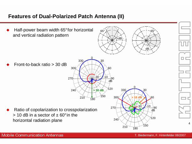
Features of Dual-Polarized Patch Antenna (II)
� Half-power beam width 65°for horizontal and vertical radiation pattern
� Front-to-back ratio > 30 dB
� Ratio of copolarization to crosspolarization> 10 dB in a sector of ± 60°in thehorizontal radiation plane
65°
dB
65°
dB
0330
300
270
240
210 150
120
90
60
30
-10dB
180
-30
0330
300
270
240
210 150
120
90
60
30
-10dB
180
-30
> 30 dB
> 10 dB

T. Biedermann, F. Hirtenfelder 08/2007
5
Layout and Decoupling

T. Biedermann, F. Hirtenfelder 08/2007
6
Layout and Decoupling
1 2
Microstrip crossover

T. Biedermann, F. Hirtenfelder 08/2007
7
Plastic Frame, Shape and Size of Groundplane (I)

T. Biedermann, F. Hirtenfelder 08/2007
8
Shape and Size of Groundplane (II)
f = 2.11 GHz
cornersremoved
additionalstripes
+60° -60° +60° -60° +60° -60°1.92 -21.9 -24.1 -10.0 -14.3 -13.5 -19.21.95 -17.7 -34.1 -9.2 -13.6 -14.0 -16.31.98 -16.4 -35.1 -6.0 -12.4 -15.6 -15.52.11 -20.3 -21.5 -10.0 -13.5 -10.9 -21.52.14 -37.7 -16.9 -10.3 -14.3 -10.5 -16.82.17 -31.3 -14.4 -10.5 -14.1 -10.8 -16.0
Frequency (GHz)
Level of Crosspolarizationquadratic
ground planeground plane with corners removed
ground plane with additional stripes

T. Biedermann, F. Hirtenfelder 08/2007
9
Mesh-Settings: Various Meshdensities
Solver Statistics:
Number of meshcells: 378525 Excitation duration: 3.554549e+000 ns Calculation time for excitation: 677 sNumber of calculated pulse widths: 11.9352 Steady state accuracy limit: -30 dB Simulated number of time steps: 59882 Maximum number of time steps: 100345 Time step width:
without subcycles: 7.084636e-004 nsused: 7.084636e-004 ns
Time step factor: 0.481358
Number of processors used: 2 Matrix calculation time: 426 sSolver time: 5954 s
------------Total time: 6380 s (= 1 h, 46 m, 20 s )
Solver Statistics:
Number of meshcells: 3281760
Excitation duration: 3.554549e+000 ns Calculation time for excitation: 43277 sNumber of calculated pulse widths: 6.44656 Steady state accuracy limit: -40 dB Simulated number of time steps: 237464 Maximum number of time steps: 736715 Time step width:
without subcycles: 9.649714e-005 nsused: 9.649714e-005 ns
Time step factor: 0.474657
Number of processors used: 1 Matrix calculation time: 1632 sSolver time: 240963 s
------------Total time: 242595 s (= 67 h, 23 m, 15 s )
Coarse Mesh
Fine Mesh

T. Biedermann, F. Hirtenfelder 08/2007
10
Subgrid cycling statistics:
Number of cycle levels: 7Number of cycled components: Level Sub: 39644 (1.08 %)Level 1: 746558 (20.25 %)Level 2: 1678589 (45.53 %)Level 3: 599867 (16.27 %)Level 4: 287517 (7.80 %)Level 5: 294356 (7.98 %)Level 6: 40225 (1.09 %)
Solver Statistics:
Number of meshcells: 378274
Excitation duration: 3.554549e+000 ns Calculation time for excitation: 2722 sNumber of calculated pulse widths: 6.43367 Steady state accuracy limit: -30 dB Simulated number of time steps: 76875 Maximum number of time steps: 238976 Time step width:
without subcycles: 2.476335e-004 nsused: 2.974805e-004 ns
Time step factor: 0.659918
Number of processors used: 2 Matrix calculation time: 2 sSolver time: 15849 s
------------Total time: 15851 s (= 4 h, 24 m, 11 s )
Mesh-Settings: Subgrid Mesh

T. Biedermann, F. Hirtenfelder 08/2007
11
Comparison of S-Parameters vs. Mesh-Settings
„Simulation results didn‘tkeep pace with prototyping“

T. Biedermann, F. Hirtenfelder 08/2007
12
CST-DesignStudio: Split-up into Sub-Models

T. Biedermann, F. Hirtenfelder 08/2007
13
CST-DesignStudio: Split-up into Sub-Models
without frame

T. Biedermann, F. Hirtenfelder 08/2007
14
Only the feed-lines are separated into different submodels; the cavity and slotplate are unchanged to preserve the 3D-modes
CST-DesignStudio: Split-up into Sub-Models
Coax
MicroStrips
T. Biedermann, F. Hirtenfelder 08/2007
15
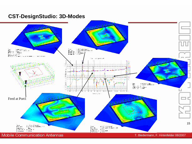
CST-DesignStudio: 3D-Modes
Feed at Port1

T. Biedermann, F. Hirtenfelder 08/2007
16
CST-DesignStudio: Patch and MicroStrip-crossover
MicroStrip-Crossover
Patch-Submodel

T. Biedermann, F. Hirtenfelder 08/2007
17
CST-DesignStudio: Complete Model
MicroStrip-Crossover
MicroStrips

T. Biedermann, F. Hirtenfelder 08/2007
18
Farfield-Check:
Ratio of copolarization to crosspolarization > 10 dB in a sector of ± 60° in the horizontal radiation plane
Half-power beam width 65° for horizontal and vertical radiation pattern

T. Biedermann, F. Hirtenfelder 08/2007
19
Summary
• Dual-polarized microstrip patch antenna element• Fulfills all requirements for mobile base station antenna• Use of resonant housing to improve electrical parameters• Simulation and Measurements are in good agreement
PBA™ and Subgrid – Meshing techniques create smallermodels reducing runtimes drasticallyCST-DS using even smaller CST-MWS submodelsshortens design cycles